
User Manual
Page 3
......vii About this guide...viii SABERTOOTH P67 specifications summary x Chapter 1: Product introduction 1.1 Welcome!...1-1 1.2 Package contents 1-1 1.3 Special features 1-2 1.3.1 Product highlights 1-2 1.3.2 "Ultimate COOL!" Thermal Solutions 1-3 1.3.3 "TUF ENGINE!" Power Design 1-3 1.3.4 "Safe & Stable!" Guardian Angel 1-4 1.3.5 ASUS EZ DIY 1-4 1.3.6 Other ... DIMM installation 2-29 2.3.5 Motherboard installation 2-30 2.3.6 ATX Power connection 2-32 2.3.7 SATA device connection 2-33 2.3.8 Front I/O Connector 2-34 2.3.9 Expension Card installation 2-35 iii
......vii About this guide...viii SABERTOOTH P67 specifications summary x Chapter 1: Product introduction 1.1 Welcome!...1-1 1.2 Package contents 1-1 1.3 Special features 1-2 1.3.1 Product highlights 1-2 1.3.2 "Ultimate COOL!" Thermal Solutions 1-3 1.3.3 "TUF ENGINE!" Power Design 1-3 1.3.4 "Safe & Stable!" Guardian Angel 1-4 1.3.5 ASUS EZ DIY 1-4 1.3.6 Other ... DIMM installation 2-29 2.3.5 Motherboard installation 2-30 2.3.6 ATX Power connection 2-32 2.3.7 SATA device connection 2-33 2.3.8 Front I/O Connector 2-34 2.3.9 Expension Card installation 2-35 iii
User Manual
Page 12
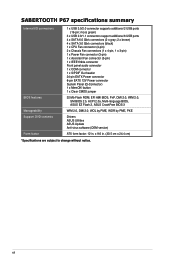
... 2.0, SM BIOS 2.5, ACPI 2.0a, Multi-language BIOS, ASUS EZ Flash 2, ASUS CrashFree BIOS 3 WfM 2.0, DMI 2.0, WOL by PME, WOR by PME, PXE Drivers ASUS Utilities ASUS Update Anti-virus software (OEM version) ATX form factor: 12 in . (30.5 cm x 24.4 cm) *Specifications are subject to change without notice. SABERTOOTH P67 specifications summary Internal I/O connectors BIOS features Manageability...
... 2.0, SM BIOS 2.5, ACPI 2.0a, Multi-language BIOS, ASUS EZ Flash 2, ASUS CrashFree BIOS 3 WfM 2.0, DMI 2.0, WOL by PME, WOR by PME, PXE Drivers ASUS Utilities ASUS Update Anti-virus software (OEM version) ATX form factor: 12 in . (30.5 cm x 24.4 cm) *Specifications are subject to change without notice. SABERTOOTH P67 specifications summary Internal I/O connectors BIOS features Manageability...
User Manual
Page 19
... it on a grounded antistatic pad or in the bag that came with the component. • Before you install or remove any component, ensure that the ATX power supply is switched off or the power cord is detached from the power supply. ASUS SABERTOOTH P67 2-1
... it on a grounded antistatic pad or in the bag that came with the component. • Before you install or remove any component, ensure that the ATX power supply is switched off or the power cord is detached from the power supply. ASUS SABERTOOTH P67 2-1

User Manual
Page 21
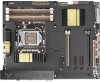
...pin AAFP) Page 2-21 2-20 2-4 2-5 2-13 2-18 2-17 2-15 2-16 2-12 2-23 2-17 2-14 2-18 2-19 2-19 2-21 Chapter 2 ASUS SABERTOOTH P67 2-3 USB 3.0 connector (20-1 pin USB3_34) 7. LGA1155 CPU socket 4. Digital audio connector (4-1 pin SPDIF_OUT) 17. switch 6. System panel connector (20-8 pin... (10-1 pin IE1394_2) 16. Clear RTC RAM (3-pin CLRTC) 11. Standby power LED (SB_PWR) 14. Layout contents Connectors/Jumpers/Slots 1. ATX power connectors (24-pin EATXPWR, 8-pin EATX12V) 2. CPU, chassis, power, and assistant fan connectors (4-pin CPU_FAN, 4-pin CHA_FAN1, 3-pin CHA_FAN2...
...pin AAFP) Page 2-21 2-20 2-4 2-5 2-13 2-18 2-17 2-15 2-16 2-12 2-23 2-17 2-14 2-18 2-19 2-19 2-21 Chapter 2 ASUS SABERTOOTH P67 2-3 USB 3.0 connector (20-1 pin USB3_34) 7. LGA1155 CPU socket 4. Digital audio connector (4-1 pin SPDIF_OUT) 17. switch 6. System panel connector (20-8 pin... (10-1 pin IE1394_2) 16. Clear RTC RAM (3-pin CLRTC) 11. Standby power LED (SB_PWR) 14. Layout contents Connectors/Jumpers/Slots 1. ATX power connectors (24-pin EATXPWR, 8-pin EATX12V) 2. CPU, chassis, power, and assistant fan connectors (4-pin CPU_FAN, 4-pin CHA_FAN1, 3-pin CHA_FAN2...

User Manual
Page 39
...;to��t�h�i�s�c��o�n�n�e��c�to [HD]; ATX power connectors (24-pin EATXPWR; 8-pin EATX12V) These connectors are designed to fit these connectors in ... panel audio connector (10-1 pin AAFP) This connector is set the item to this connector is for ATX power supply plugs. Connect one orientation. Find the proper orientation and push down firmly until the connectors completely...We recommend that supports either HD Audio or legacy AC`97 audio standard. Chapter 2 ASUS SABERTOOTH P67 2-21
...;to��t�h�i�s�c��o�n�n�e��c�to [HD]; ATX power connectors (24-pin EATXPWR; 8-pin EATX12V) These connectors are designed to fit these connectors in ... panel audio connector (10-1 pin AAFP) This connector is set the item to this connector is for ATX power supply plugs. Connect one orientation. Find the proper orientation and push down firmly until the connectors completely...We recommend that supports either HD Audio or legacy AC`97 audio standard. Chapter 2 ASUS SABERTOOTH P67 2-21
User Manual
Page 41
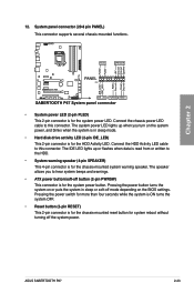
...-8 pin PANEL) This connector supports several chassis-mounted functions. Connect the HDD Activity LED cable to hear system beeps and warnings. • ATX power button/soft-off button (2-pin PWRSW) This connector is in sleep or soft-off the system power. Pressing the power switch for more... puts the system in sleep mode. • Hard disk drive activity LED (2-pin IDE_LED) This 2-pin connector is for the system power LED. ASUS SABERTOOTH P67 2-23 Pressing the power button turns the system on the BIOS settings. Chapter 2 • System power LED (2-pin PLED) This 2-pin connector ...
...-8 pin PANEL) This connector supports several chassis-mounted functions. Connect the HDD Activity LED cable to hear system beeps and warnings. • ATX power button/soft-off button (2-pin PWRSW) This connector is in sleep or soft-off the system power. Pressing the power switch for more... puts the system in sleep mode. • Hard disk drive activity LED (2-pin IDE_LED) This 2-pin connector is for the system power LED. ASUS SABERTOOTH P67 2-23 Pressing the power button turns the system on the BIOS settings. Chapter 2 • System power LED (2-pin PLED) This 2-pin connector ...


