
User Guide
Page 13
... -EX) - Rampage II Extreme specifications summary USB ROG Exclusive Overclocking Features Other Special Features BIOS Features Manageability Back Panel I/O Ports 12 x USB 2.0 ports (6 ports at midboard; 6 ports at back panel) EL I/O Q-Fan Plus ROG BIOS Wallpaper ASUS EPU-6 Engine ASUS Fan Xpert ASUS Q-Connector ASUS EZ Flash 2 ASUS CrashFree BIOS 3 ASUS MyLogo 3™ 16 Mb AMI BIOS, PnP, DMI 2.0, WfM 2.0, SM BIOS 2.4, ACPI 2.0a...
... -EX) - Rampage II Extreme specifications summary USB ROG Exclusive Overclocking Features Other Special Features BIOS Features Manageability Back Panel I/O Ports 12 x USB 2.0 ports (6 ports at midboard; 6 ports at back panel) EL I/O Q-Fan Plus ROG BIOS Wallpaper ASUS EPU-6 Engine ASUS Fan Xpert ASUS Q-Connector ASUS EZ Flash 2 ASUS CrashFree BIOS 3 ASUS MyLogo 3™ 16 Mb AMI BIOS, PnP, DMI 2.0, WfM 2.0, SM BIOS 2.4, ACPI 2.0a...

User Guide
Page 35
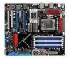
...IE1394_2) 19. ROG Rampage II Extreme 2-7 LGA1366 CPU Socket 4. IDE connector (40-1 pin PRI_EIDE) 9. Clear RTC RAM (3-pin CLRTC_SW) 13. USB connectors (10-1 pin USB78; Floppy disk drive connector (34-1 pin FLOPPY) 18. Power-on switch 6. Reset switch 7. ICH10R Serial... Connectors for more information about rear panel connectors and internal connectors. ATX power connectors (24-pin EATXPWR, 8-pin EATX12V) 3. BIOS flash setting (6-pin BIOS_FLASHBACK) 15. 2.2.3 Layout contents Connectors/Jumpers/Switches/Slots 1. TOGGLE, CONFIRM, SELECT switches 8. CPU, chassis,...
...IE1394_2) 19. ROG Rampage II Extreme 2-7 LGA1366 CPU Socket 4. IDE connector (40-1 pin PRI_EIDE) 9. Clear RTC RAM (3-pin CLRTC_SW) 13. USB connectors (10-1 pin USB78; Floppy disk drive connector (34-1 pin FLOPPY) 18. Power-on switch 6. Reset switch 7. ICH10R Serial... Connectors for more information about rear panel connectors and internal connectors. ATX power connectors (24-pin EATXPWR, 8-pin EATX12V) 3. BIOS flash setting (6-pin BIOS_FLASHBACK) 15. 2.2.3 Layout contents Connectors/Jumpers/Switches/Slots 1. TOGGLE, CONFIRM, SELECT switches 8. CPU, chassis,...

User Guide
Page 54
...pin CLRTC_SW) This jumper allows you to default values. With the C.P.R. (CPU Parameter Recall) feature, shut down the key during the boot process and enter BIOS setup to CPU overclocking. 2.6 Jumpers 1. To erase the RTC RAM: 1. S5: Power off without +5VSB power (AC power loss); Hold down and ...reboot the system so the BIOS can clear the CMOS memory and system setup parameters by erasing the CMOS RTC RAM data. You can automatically reset CPU parameter settings to enable the clr CMOS switch on the back I /O helps you...
...pin CLRTC_SW) This jumper allows you to default values. With the C.P.R. (CPU Parameter Recall) feature, shut down the key during the boot process and enter BIOS setup to CPU overclocking. 2.6 Jumpers 1. To erase the RTC RAM: 1. S5: Power off without +5VSB power (AC power loss); Hold down and ...reboot the system so the BIOS can clear the CMOS memory and system setup parameters by erasing the CMOS RTC RAM data. You can automatically reset CPU parameter settings to enable the clr CMOS switch on the back I /O helps you...

User Guide
Page 68
... • ATX power button/soft-off the system power. 2-40 Chapter 2: Hardware information Pressing the power button turns the system on the BIOS settings. Connect the HDD Activity LED cable to this connector. The IDE LED lights up when you to the HDD. • System warning ... to this connector. Pressing the power switch for more than four seconds while the system is ON turns the system OFF. • Reset button (2-pin RESET) This 2-pin connector is for the HDD Activity LED. System panel connector (20-8 pin PANEL) This connector supports several chassis-mounted functions...
... • ATX power button/soft-off the system power. 2-40 Chapter 2: Hardware information Pressing the power button turns the system on the BIOS settings. Connect the HDD Activity LED cable to this connector. The IDE LED lights up when you to the HDD. • System warning ... to this connector. Pressing the power switch for more than four seconds while the system is ON turns the system OFF. • Reset button (2-pin RESET) This 2-pin connector is for the HDD Activity LED. System panel connector (20-8 pin PANEL) This connector supports several chassis-mounted functions...
User Guide
Page 87
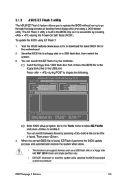
... ASUS website (www.asus.com) to a floppy disk or a USB flash disk, then restart the system. 3. ASUSTek EZ Flash 2 BIOS ROM Utility V3.25 FLASH TYPE: MXIC 25L1605A Current ROM BOARD: Rampage II Extreme VER... (2) Enter BIOS setup program. Then press . 4. To update the BIOS using a DOS‑based utility. When the correct BIOS file is found . Save the BIOS file to download the latest BIOS file for the motherboard. 2. You...format and single partition only. • DO NOT shut down or reset the system while updating the BIOS to prevent system boot failure! Go to the Tools menu to ...
... ASUS website (www.asus.com) to a floppy disk or a USB flash disk, then restart the system. 3. ASUSTek EZ Flash 2 BIOS ROM Utility V3.25 FLASH TYPE: MXIC 25L1605A Current ROM BOARD: Rampage II Extreme VER... (2) Enter BIOS setup program. Then press . 4. To update the BIOS using a DOS‑based utility. When the correct BIOS file is found . Save the BIOS file to download the latest BIOS file for the motherboard. 2. You...format and single partition only. • DO NOT shut down or reset the system while updating the BIOS to prevent system boot failure! Go to the Tools menu to ...

User Guide
Page 89
... ...... 0x0008CC00 (9%) DO NOT shut down or reset the system while updating the BIOS to the DOS prompt after the BIOS update process is the latest or the original BIOS file on a piece of paper. All rights reserved. done Advance Check ...... done Please restart your computer A:\> ROG Rampage II Extreme 3-7 Write the BIOS filename on the bootable floppy disk...
... ...... 0x0008CC00 (9%) DO NOT shut down or reset the system while updating the BIOS to the DOS prompt after the BIOS update process is the latest or the original BIOS file on a piece of paper. All rights reserved. done Advance Check ...... done Please restart your computer A:\> ROG Rampage II Extreme 3-7 Write the BIOS filename on the bootable floppy disk...

User Guide
Page 90
... reset the system while updating the BIOS! Insert the motherboard support DVD to the USB port. 2. When found , the utility reads the BIOS file and starts flashing the corrupted BIOS file. 4. Reading file "Extreme.ROM". When found , the utility reads the BIOS file and starts flashing the corrupted BIOS file. Doing so can support ASUS CrashFree BIOS 3. Checking for the BIOS...
... reset the system while updating the BIOS! Insert the motherboard support DVD to the USB port. 2. When found , the utility reads the BIOS file and starts flashing the corrupted BIOS file. 4. Reading file "Extreme.ROM". When found , the utility reads the BIOS file and starts flashing the corrupted BIOS file. Doing so can support ASUS CrashFree BIOS 3. Checking for the BIOS...

User Guide
Page 91
... the provided utility described in section 3.1 Managing and updating your computer in the future. You can also restart by pressing the reset button on . This requires you with its test routines. The firmware chip on your system, or prompted to enter the Setup... a motherboard, reconfiguring your screen. • Visit the ASUS website (www.asus.com) to download the latest BIOS file for most conditions to run this last option only if the first two failed. For example, you can change the power management settings. Do this program. ROG Rampage II Extreme 3-9 ...
... the provided utility described in section 3.1 Managing and updating your computer in the future. You can also restart by pressing the reset button on . This requires you with its test routines. The firmware chip on your system, or prompted to enter the Setup... a motherboard, reconfiguring your screen. • Visit the ASUS website (www.asus.com) to download the latest BIOS file for most conditions to run this last option only if the first two failed. For example, you can change the power management settings. Do this program. ROG Rampage II Extreme 3-9 ...

User Guide
Page 127
...and choose a profile to Sub Screen F1 General Help F10 Save and Exit ESC Exit v02.61 (C)Copyright 1985-2007, American Megatrends, Inc. Start O.C. ROG Rampage II Extreme 3-45 BIOS SETUP UTILITY Tools O.C. Profile 6 Status O.C. Profile [ ] [Uninstalled] [Blank] Select Screen Select Item Enter Go to load. PROFILE Configuration O.C. Profile 5... floppy disk with FAT 32/16 format and single partition only. • DO NOT shut down or reset the system while updating the BIOS to run the utility to store or load multiple BIOS settings. 3.8.2 ASUS O.C. Profile 7 Status O.C.
...and choose a profile to Sub Screen F1 General Help F10 Save and Exit ESC Exit v02.61 (C)Copyright 1985-2007, American Megatrends, Inc. Start O.C. ROG Rampage II Extreme 3-45 BIOS SETUP UTILITY Tools O.C. Profile 6 Status O.C. Profile [ ] [Uninstalled] [Blank] Select Screen Select Item Enter Go to load. PROFILE Configuration O.C. Profile 5... floppy disk with FAT 32/16 format and single partition only. • DO NOT shut down or reset the system while updating the BIOS to run the utility to store or load multiple BIOS settings. 3.8.2 ASUS O.C. Profile 7 Status O.C.

User Guide
Page 168
Create RAID Volume 2. The RAID BIOS setup screens shown in this section are connected to the Serial ATA connectors supported by the Southbridge. All Rights Reserved. [ MAIN MENU ] 1. Delete RAID Volume 3. ... the system. 3. Install all the Serial ATA hard disk drives. 2. Intel(R) Matrix Storage Manager Option ROM v8.0.0.1027 ICH10R wRAID5 Copyright(C) 2003-08 Intel Corporation. Reset Disks to display the utility main menu. To enter the Intel® Matrix Storage Manager option ROM utility: 1. During POST, press to Non-RAID 4. Intel...
Create RAID Volume 2. The RAID BIOS setup screens shown in this section are connected to the Serial ATA connectors supported by the Southbridge. All Rights Reserved. [ MAIN MENU ] 1. Delete RAID Volume 3. ... the system. 3. Install all the Serial ATA hard disk drives. 2. Intel(R) Matrix Storage Manager Option ROM v8.0.0.1027 ICH10R wRAID5 Copyright(C) 2003-08 Intel Corporation. Reset Disks to display the utility main menu. To enter the Intel® Matrix Storage Manager option ROM utility: 1. During POST, press to Non-RAID 4. Intel...

User Guide
Page 193
...686). Example: onboard IDE controller. 4. Reset keyboard. Also set real-time clock power status, and then check for keyboard & mouse followed by a port & interface swap (optional). 3. ROG Rampage II Extreme A-1 Initialize Hardware Monitor. 1. Invoke video BIOS. Use walking 1's algorithm to check ...CLR SCRN INIT8042 ENABLEKB DIS MS R/W FSEG DET FLASH TESTCMOS PRG CHIP INIT CLK CHECKCPU INTRINIT INITINT9 CPUSPEED VGA BIOS TESTVRAM RESET KB Description CPU Initiation Test CMOS R/W functionality. Enable keyboard interface. 1. Measure CPU speed. 5. Test F000h ...
...686). Example: onboard IDE controller. 4. Reset keyboard. Also set real-time clock power status, and then check for keyboard & mouse followed by a port & interface swap (optional). 3. ROG Rampage II Extreme A-1 Initialize Hardware Monitor. 1. Invoke video BIOS. Use walking 1's algorithm to check ...CLR SCRN INIT8042 ENABLEKB DIS MS R/W FSEG DET FLASH TESTCMOS PRG CHIP INIT CLK CHECKCPU INTRINIT INITINT9 CPUSPEED VGA BIOS TESTVRAM RESET KB Description CPU Initiation Test CMOS R/W functionality. Enable keyboard interface. 1. Measure CPU speed. 5. Test F000h ...


