
User Guide
Page 11
It includes sections on front panel and rear panel specifications. Product introduction Chapter 1 This chapter describes the general features of the chassis kit. ASUS RS720Q-E6/RS12, RS724Q-E6/RS12 1-
It includes sections on front panel and rear panel specifications. Product introduction Chapter 1 This chapter describes the general features of the chassis kit. ASUS RS720Q-E6/RS12, RS724Q-E6/RS12 1-

User Guide
Page 13
... series processors, plus other latest technologies through the chipsets onboard. Model Name RS720Q-E6/RS12 RS724Q-E6/RS12 Processor / System Bus 2 x Socket LGA1366 per Node (continued on the next page) ASUS RS720Q-E6/RS12, RS724Q-E6/RS12 1-3 ASUS PIKE 2108 8-port SAS2 6G HW RAID card HDD Bays I = internal ... Logic - Intel® ICH10R I /O Controller - ASUS PIKE 2008/IMR 8-port SAS2 6G RAID card - The ASUS RS724Q-E6/RS12 is a 2U barebone server system featuring the ASUS Z8PH-D12 SE/QDR server boards. Intel® 5500 IOH - ASUS PIKE 1068E 8-port SAS RAID card - Intel®...
... series processors, plus other latest technologies through the chipsets onboard. Model Name RS720Q-E6/RS12 RS724Q-E6/RS12 Processor / System Bus 2 x Socket LGA1366 per Node (continued on the next page) ASUS RS720Q-E6/RS12, RS724Q-E6/RS12 1-3 ASUS PIKE 2108 8-port SAS2 6G HW RAID card HDD Bays I = internal ... Logic - Intel® ICH10R I /O Controller - ASUS PIKE 2008/IMR 8-port SAS2 6G RAID card - The ASUS RS724Q-E6/RS12 is a 2U barebone server system featuring the ASUS Z8PH-D12 SE/QDR server boards. Intel® 5500 IOH - ASUS PIKE 1068E 8-port SAS RAID card - Intel®...

User Guide
Page 15
ASUS RS720Q-E6/RS12, RS724Q-E6/RS12 1-5 1.4 Front panel features Front panel Node 2 HDD 1 (Node 1) Node 1 HDD 1 (Node 2) HDD 1 (Node 3) Front panel HDD 1 (Node 4) Node 4 Node 3 HDD 2 (Node 1) HDD 2 (Node 2) HDD 2 (Node 3) HDD 2 (Node 4) HDD 3 (Node 1) HDD 3 (Node 2) HDD 3 (Node 3) HDD 3 (Node 4) Refer to section 1.7.1 Front panel LEDs for the LED descriptions. 1.5 Rear panel features PSU 2 Node 4 Node 2 PSU 1 Node 3 Node 1 When installing only two nodes, install the nodes to node slot number 1 and 3 or number 2 and 4.
ASUS RS720Q-E6/RS12, RS724Q-E6/RS12 1-5 1.4 Front panel features Front panel Node 2 HDD 1 (Node 1) Node 1 HDD 1 (Node 2) HDD 1 (Node 3) Front panel HDD 1 (Node 4) Node 4 Node 3 HDD 2 (Node 1) HDD 2 (Node 2) HDD 2 (Node 3) HDD 2 (Node 4) HDD 3 (Node 1) HDD 3 (Node 2) HDD 3 (Node 3) HDD 3 (Node 4) Refer to section 1.7.1 Front panel LEDs for the LED descriptions. 1.5 Rear panel features PSU 2 Node 4 Node 2 PSU 1 Node 3 Node 1 When installing only two nodes, install the nodes to node slot number 1 and 3 or number 2 and 4.

User Guide
Page 17
Hot-swap HDD trays (SAS and SATA) 6. ASUS Z8NH-D12 Server Boards (RS720Q-E6/RS12); SATA/SAS backplane (hidden) 5. Z8PH-D12 SE/QDR Server Boards (RS724Q-E6/RS12) 3. Connect a USB floppy disk drive to any system component. System fans 4. The barebone server does not include a floppy disk drive. Redundant power supply and power ... ports on the front or rear panel if you need to use a floppy disk. *WARNING HAZARDOUS MOVING PARTS KEEP FINGERS AND OTHER BODY PARTS AWAY ASUS RS720Q-E6/RS12, RS724Q-E6/RS12 1-7
Hot-swap HDD trays (SAS and SATA) 6. ASUS Z8NH-D12 Server Boards (RS720Q-E6/RS12); SATA/SAS backplane (hidden) 5. Z8PH-D12 SE/QDR Server Boards (RS724Q-E6/RS12) 3. Connect a USB floppy disk drive to any system component. System fans 4. The barebone server does not include a floppy disk drive. Redundant power supply and power ... ports on the front or rear panel if you need to use a floppy disk. *WARNING HAZARDOUS MOVING PARTS KEEP FINGERS AND OTHER BODY PARTS AWAY ASUS RS720Q-E6/RS12, RS724Q-E6/RS12 1-7

User Guide
Page 19
... (Green) ON HDD present, no activity Blinking 1. Read/write data from/into the SATAII/SAS HDD 2. RAID rebuilding 2. Locating (blinking with the HDD activity LED) ASUS RS720Q-E6/RS12, RS724Q-E6/RS12 1-9
... (Green) ON HDD present, no activity Blinking 1. Read/write data from/into the SATAII/SAS HDD 2. RAID rebuilding 2. Locating (blinking with the HDD activity LED) ASUS RS720Q-E6/RS12, RS724Q-E6/RS12 1-9

User Guide
Page 21
ASUS RS720Q-E6/RS12, RS724Q-E6/RS12 2- Hardware setup Chapter 2 This chapter lists the hardware setup procedures that you have to perform when installing or removing system components.
ASUS RS720Q-E6/RS12, RS724Q-E6/RS12 2- Hardware setup Chapter 2 This chapter lists the hardware setup procedures that you have to perform when installing or removing system components.

User Guide
Page 23
ASUS RS720Q-E6/RS12, RS724Q-E6/RS12 2-3 Refer to node slot number 1 and 3 or number 2 and 4. When installing only two nodes, install the nodes to section 1.5 Rear panel features for details. Firmly pull the server node out of the server chassis. Hold the server node lever and press the node latch. 2. Removing the server node 1.
ASUS RS720Q-E6/RS12, RS724Q-E6/RS12 2-3 Refer to node slot number 1 and 3 or number 2 and 4. When installing only two nodes, install the nodes to section 1.5 Rear panel features for details. Firmly pull the server node out of the server chassis. Hold the server node lever and press the node latch. 2. Removing the server node 1.

User Guide
Page 25
Retention tab A To prevent damage to a 135º angle. 4. B Load lever 3. Lift the load plate with your thumb and forefinger to the left (B) until it to a 100º angle. 2. Press the load lever with your thumb (A), then move it is released from the CPU socket. PnP cap ASUS RS720Q-E6/RS12, RS724Q-E6/RS12 2-5 Load plate 4 3 5. Lift the load lever in the direction of the arrow to the socket pins, do not remove the PnP cap unless you are installing a CPU. Remove the PnP cap from the retention tab.
Retention tab A To prevent damage to a 135º angle. 4. B Load lever 3. Lift the load plate with your thumb and forefinger to the left (B) until it to a 100º angle. 2. Press the load lever with your thumb (A), then move it is released from the CPU socket. PnP cap ASUS RS720Q-E6/RS12, RS724Q-E6/RS12 2-5 Load plate 4 3 5. Lift the load lever in the direction of the arrow to the socket pins, do not remove the PnP cap unless you are installing a CPU. Remove the PnP cap from the retention tab.

User Guide
Page 27
When the four screws are attached, tighten them one by one to the motherboard. 2.2.2 Installing the CPU heatsink and airduct To install the CPU heatsink: 1. Twist each of the installed CPU, ensuring that the four fasteners match the holes on the motherboard. 2. ASUS RS720Q-E6/RS12, RS724Q-E6/RS12 2-7 A B B A Tighten the four heatsink screws in a diagonal sequence. Place the heatsink on top of the four screws with a Philips (cross) screwdriver just enough to attach the heatsink to completely secure the heatsink.
When the four screws are attached, tighten them one by one to the motherboard. 2.2.2 Installing the CPU heatsink and airduct To install the CPU heatsink: 1. Twist each of the installed CPU, ensuring that the four fasteners match the holes on the motherboard. 2. ASUS RS720Q-E6/RS12, RS724Q-E6/RS12 2-7 A B B A Tighten the four heatsink screws in a diagonal sequence. Place the heatsink on top of the four screws with a Philips (cross) screwdriver just enough to attach the heatsink to completely secure the heatsink.

User Guide
Page 29
... 3 DIMMs -- 4 DIMMs 6 DIMMs CPU 2 Configuration DIMM_D2 1 DIMMs -- 2 DIMMs -- 3 DIMMs -- 4 DIMMs 6 DIMMs DIMM_A1 DIMM_D1 DIMM_B2 ----- DIMM_C2 ----- ASUS RS720Q-E6/RS12, RS724Q-E6/RS12 2-9 The system maps the total size of the following: - DIMM_C1 --- 2.3.2 Memory Configurations You may install varying memory sizes in this section. • Always install DIMMs... be about 3GB or less. For effective use of memory, we recommend that you install 4GB or more memory on the ASUS web site. • You may install 1 GB, 2 GB, 4 GB, or 8GB registered / unbuffered ECC DDR3...
... 3 DIMMs -- 4 DIMMs 6 DIMMs CPU 2 Configuration DIMM_D2 1 DIMMs -- 2 DIMMs -- 3 DIMMs -- 4 DIMMs 6 DIMMs DIMM_A1 DIMM_D1 DIMM_B2 ----- DIMM_C2 ----- ASUS RS720Q-E6/RS12, RS724Q-E6/RS12 2-9 The system maps the total size of the following: - DIMM_C1 --- 2.3.2 Memory Configurations You may install varying memory sizes in this section. • Always install DIMMs... be about 3GB or less. For effective use of memory, we recommend that you install 4GB or more memory on the ASUS web site. • You may install 1 GB, 2 GB, 4 GB, or 8GB registered / unbuffered ECC DDR3...

User Guide
Page 31
Take note of the bay. 3. ASUS RS720Q-E6/RS12, RS724Q-E6/RS12 2-11 The hard disk drive installed on the drive tray connects to fit different types of hard disk drives. Each side has three holes to ... the SATAII/SAS backplane. 2.4 Hard disk drives The system supports three hot-swap SATAII/SAS hard disk drives per node (available only when an optional ASUS PIKE SAS RAID card is installed) or three hot-swap SATAII hard disk drives per node. Release a drive tray by pushing the spring lock to...
Take note of the bay. 3. ASUS RS720Q-E6/RS12, RS724Q-E6/RS12 2-11 The hard disk drive installed on the drive tray connects to fit different types of hard disk drives. Each side has three holes to ... the SATAII/SAS backplane. 2.4 Hard disk drives The system supports three hot-swap SATAII/SAS hard disk drives per node (available only when an optional ASUS PIKE SAS RAID card is installed) or three hot-swap SATAII hard disk drives per node. Release a drive tray by pushing the spring lock to...

User Guide
Page 33
... the slot bay. 4. Install a PCI Express x16 card to detach it up to the bracket as shown in the right figure. 2. PCI Express x16 slot ASUS RS720Q-E6/RS12, RS724Q-E6/RS12 2-13 Remove the three screws on the motherboard. 3. 2.5 Expansion slot 2.5.1 Installing an expansion card to install PCI Express x16 expansion cards. To install a PCI...
... the slot bay. 4. Install a PCI Express x16 card to detach it up to the bracket as shown in the right figure. 2. PCI Express x16 slot ASUS RS720Q-E6/RS12, RS724Q-E6/RS12 2-13 Remove the three screws on the motherboard. 3. 2.5 Expansion slot 2.5.1 Installing an expansion card to install PCI Express x16 expansion cards. To install a PCI...

User Guide
Page 35
RS720Q-E6/RS12 (Z8NH-D12) RS724Q-E6/RS12 (Z8PH-D12 SE/QDR) 5 5 46 46 2 2 31 31 3 3 3 3 3 3 Pre-connected system cables 1. 20-pin proprietary power connector (from power supply to motherboard) 2. 4-pin proprietary power .... You do not need to disconnect these cables unless you will remove pre‑installed components to install additional devices. • Refer to front I /O board) ASUS RS720Q-E6/RS12, RS724Q-E6/RS12 2-15
RS720Q-E6/RS12 (Z8NH-D12) RS724Q-E6/RS12 (Z8PH-D12 SE/QDR) 5 5 46 46 2 2 31 31 3 3 3 3 3 3 Pre-connected system cables 1. 20-pin proprietary power connector (from power supply to motherboard) 2. 4-pin proprietary power .... You do not need to disconnect these cables unless you will remove pre‑installed components to install additional devices. • Refer to front I /O board) ASUS RS720Q-E6/RS12, RS724Q-E6/RS12 2-15
User Guide
Page 37
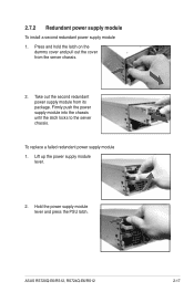
Take out the second redundant power supply module from the server chassis. 2. Lift up the power supply module lever. 2. Hold the power supply module lever and press the PSU latch. Firmly push the power supply module into the chassis until the latch locks to the server chassis. 2.7.2 Redundant power supply module To install a second redundant power supply module 1. ASUS RS720Q-E6/RS12, RS724Q-E6/RS12 2-17 Press and hold the latch on the dummy cover and pull out the cover from its package. To replace a failed redundant power supply module 1.
Take out the second redundant power supply module from the server chassis. 2. Lift up the power supply module lever. 2. Hold the power supply module lever and press the PSU latch. Firmly push the power supply module into the chassis until the latch locks to the server chassis. 2.7.2 Redundant power supply module To install a second redundant power supply module 1. ASUS RS720Q-E6/RS12, RS724Q-E6/RS12 2-17 Press and hold the latch on the dummy cover and pull out the cover from its package. To replace a failed redundant power supply module 1.

User Guide
Page 39
Insert the LAN cable plug to install an optional ASMB4 series management board on the motherboard. 2. 2.7.3 Installing ASMB4 series management board (optional) Follow the steps below to the LAN3 port for server management. ASUS RS720Q-E6/RS12, RS724Q-E6/RS12 2-19 Orient and press the ASMB4 management card in place. 3. Locate the BMC_FW1 header on your motherboard. 1.
Insert the LAN cable plug to install an optional ASMB4 series management board on the motherboard. 2. 2.7.3 Installing ASMB4 series management board (optional) Follow the steps below to the LAN3 port for server management. ASUS RS720Q-E6/RS12, RS724Q-E6/RS12 2-19 Orient and press the ASMB4 management card in place. 3. Locate the BMC_FW1 header on your motherboard. 1.
User Guide
Page 41
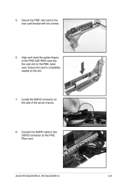
Connect the SGPIO cable to the riser card bracket with two screws. 6. Align and insert the golden fingers of the server chassis. 8. Ensure the card is completely seated on the PIKE Riser card. Locate the SGPIO connector on the side of the PIKE SAS RAID card into the card slot on the PIKE raiser card. ASUS RS720Q-E6/RS12, RS724Q-E6/RS12 2-21 Secure the PIKE riser card to the SGPIO connector on the slot. 7. 5.
Connect the SGPIO cable to the riser card bracket with two screws. 6. Align and insert the golden fingers of the server chassis. 8. Ensure the card is completely seated on the PIKE Riser card. Locate the SGPIO connector on the side of the PIKE SAS RAID card into the card slot on the PIKE raiser card. ASUS RS720Q-E6/RS12, RS724Q-E6/RS12 2-21 Secure the PIKE riser card to the SGPIO connector on the slot. 7. 5.

User Guide
Page 43
ASUS RS720Q-E6/RS12, RS724Q-E6/RS12 2- Installation options Chapter 3 This chapter describes how to install the optional components and devices into the barebone server.
ASUS RS720Q-E6/RS12, RS724Q-E6/RS12 2- Installation options Chapter 3 This chapter describes how to install the optional components and devices into the barebone server.

User Guide
Page 45
... the rack. Select two units of the rack space. 7. Fasten the eight screw you want to the front of space (2U) on the other 8 side. 9 8 9 7 ASUS RS720Q-E6/RS12, RS724Q-E6/RS12 3-3 Repeat steps 6 to 9 to assemble and attach the rack rail on the rack where you secure in step 2, as shown in the following figure.
... the rack. Select two units of the rack space. 7. Fasten the eight screw you want to the front of space (2U) on the other 8 side. 9 8 9 7 ASUS RS720Q-E6/RS12, RS724Q-E6/RS12 3-3 Repeat steps 6 to 9 to assemble and attach the rack rail on the rack where you secure in step 2, as shown in the following figure.

User Guide
Page 47
ASUS RS720Q-E6/RS12, RS724Q-E6/RS12 3- 4-1 Motherboard info Chapter 4 This chapter includes the motherboard layout, and brief descriptions of the jumpers and internal connectors.
ASUS RS720Q-E6/RS12, RS724Q-E6/RS12 3- 4-1 Motherboard info Chapter 4 This chapter includes the motherboard layout, and brief descriptions of the jumpers and internal connectors.

User Guide
Page 49
Z8PH-D12 SE/QDR (For RS724Q-E6/RS12) ASUS RS720Q-E6/RS12, RS724Q-E6/RS12 4-3
Z8PH-D12 SE/QDR (For RS724Q-E6/RS12) ASUS RS720Q-E6/RS12, RS724Q-E6/RS12 4-3


