
User Guide
Page 5
... 6.1.2 Installing hard disk drives 6-2 6.1.3 RAID controller selection 6-3 6.1.4 Setting the RAID item in BIOS 6-3 6.2 LSI Software RAID Configuration Utility 6-4 6.2.1 Creating a RAID set 6-5 6.2.2 Adding or viewing a RAID configuration 6-11 6.2.3 Initializing the virtual drives 6-12 6.2.4 Rebuilding failed drives 6-16 6.2.5 Checking the drives for data consistency 6-18 6.2.6 Deleting a RAID configuration 6-21 6.2.7 Selecting the boot drive from a RAID set 6-22 6.2.8 Enabling WriteCache 6-23 6.3 Intel® Matrix Storage Manager Option ROM Utility 6-24 6.3.1 Creating a RAID set...
... 6.1.2 Installing hard disk drives 6-2 6.1.3 RAID controller selection 6-3 6.1.4 Setting the RAID item in BIOS 6-3 6.2 LSI Software RAID Configuration Utility 6-4 6.2.1 Creating a RAID set 6-5 6.2.2 Adding or viewing a RAID configuration 6-11 6.2.3 Initializing the virtual drives 6-12 6.2.4 Rebuilding failed drives 6-16 6.2.5 Checking the drives for data consistency 6-18 6.2.6 Deleting a RAID configuration 6-21 6.2.7 Selecting the boot drive from a RAID set 6-22 6.2.8 Enabling WriteCache 6-23 6.3 Intel® Matrix Storage Manager Option ROM Utility 6-24 6.3.1 Creating a RAID set...
User Guide
Page 9
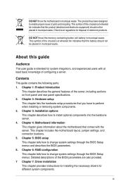
... includes the motherboard layout, jumper settings, and connector locations. 5. Chapter 2: Hardware setup This chapter lists the hardware setup procedures that the battery should not be placed in municipal waste. Chapter 5: BIOS setup This chapter tells how to change system settings through the BIOS Setup menus and describes the BIOS parameters. 6. This symbol of the crossed out wheeled bin indicates that comes with at least basic knowledge of configuring a server. Detailed...
... includes the motherboard layout, jumper settings, and connector locations. 5. Chapter 2: Hardware setup This chapter lists the hardware setup procedures that the battery should not be placed in municipal waste. Chapter 5: BIOS setup This chapter tells how to change system settings through the BIOS Setup menus and describes the BIOS parameters. 6. This symbol of the crossed out wheeled bin indicates that comes with at least basic knowledge of configuring a server. Detailed...

User Guide
Page 17
... power supply and power fan 2. System fans 4. Connect a USB floppy disk drive to use a floppy disk. *WARNING HAZARDOUS MOVING PARTS KEEP FINGERS AND OTHER BODY PARTS AWAY ASUS RS720Q-E6/RS12, RS724Q-E6/RS12 1-7 Front LED Boards Turn off the system power and detach the power supply before removing or replacing any of the USB ports on the front or rear panel if you need to any system component. The barebone server does not include a floppy disk drive. Hot-swap HDD trays (SAS and SATA) 6. ASUS Z8NH-D12 Server Boards (RS720Q-E6/RS12); SATA/SAS backplane (hidden) 5. 1.6 Internal...
... power supply and power fan 2. System fans 4. Connect a USB floppy disk drive to use a floppy disk. *WARNING HAZARDOUS MOVING PARTS KEEP FINGERS AND OTHER BODY PARTS AWAY ASUS RS720Q-E6/RS12, RS724Q-E6/RS12 1-7 Front LED Boards Turn off the system power and detach the power supply before removing or replacing any of the USB ports on the front or rear panel if you need to any system component. The barebone server does not include a floppy disk drive. Hot-swap HDD trays (SAS and SATA) 6. ASUS Z8NH-D12 Server Boards (RS720Q-E6/RS12); SATA/SAS backplane (hidden) 5. 1.6 Internal...
User Guide
Page 34
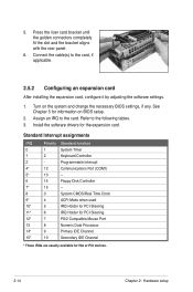
... expansion card, configure it by adjusting the software settings. 1. Turn on BIOS setup. 2. Connect the cable(s) to the card. Press the riser card bracket until the golden connectors completely fit the slot and the bracket aligns with the rear panel. 6. Install the software drivers for information on the system and change the necessary BIOS settings, if any. Programmable Interrupt 4* 12 Communications Port (COM1) 5* 13 -- 6 14 Floppy Disk Controller 7* 15 -- 8 3 System CMOS/Real Time Clock 9* 4 ACPI Mode when used...
... expansion card, configure it by adjusting the software settings. 1. Turn on BIOS setup. 2. Connect the cable(s) to the card. Press the riser card bracket until the golden connectors completely fit the slot and the bracket aligns with the rear panel. 6. Install the software drivers for information on the system and change the necessary BIOS settings, if any. Programmable Interrupt 4* 12 Communications Port (COM1) 5* 13 -- 6 14 Floppy Disk Controller 7* 15 -- 8 3 System CMOS/Real Time Clock 9* 4 ACPI Mode when used...

User Guide
Page 73
... that menu. Advanced BIOS SETUP UTILITY CPU Bridge Chipset Configuration USB Functions [1D2isUaSbBlePdorts] USB Port Configure [82X4USUBSBPoProtrsts] USB 2.0 Controller [E4naUbSlBedP]orts HDA Controller [E6naUbSlBedP]orts SMBUS Controller [E8naUbSlBedP]orts 10 USB Ports SLP_S4# Min. For example, selecting Main shows the Main menu items. The other items on the screen. 5.2.4 Menu items The highlighted item on the menu bar displays the specific items for the menu items. If an item is user-configurable, you can change...
... that menu. Advanced BIOS SETUP UTILITY CPU Bridge Chipset Configuration USB Functions [1D2isUaSbBlePdorts] USB Port Configure [82X4USUBSBPoProtrsts] USB 2.0 Controller [E4naUbSlBedP]orts HDA Controller [E6naUbSlBedP]orts SMBUS Controller [E8naUbSlBedP]orts 10 USB Ports SLP_S4# Min. For example, selecting Main shows the Main menu items. The other items on the screen. 5.2.4 Menu items The highlighted item on the menu bar displays the specific items for the menu items. If an item is user-configurable, you can change...

User Guide
Page 75
... not user-configurable. Select [CDROM] if you to [Auto] enables the LBA mode if the device supports this mode, and if the device was not previously formatted with LBA mode disabled. When set to [Disabled], the data transfer from and to the device occurs multiple sectors at a time. Configuration options: [Disabled] [Enabled] ASUS RS720Q-E6/RS12, RS724Q-E6/RS12 5-9 monitoring). Select [ARMD] (ATAPI Removable Media Device) if your device is installed in the system. These values are specifically configuring a CD-ROM drive. Type...
... not user-configurable. Select [CDROM] if you to [Auto] enables the LBA mode if the device supports this mode, and if the device was not previously formatted with LBA mode disabled. When set to [Disabled], the data transfer from and to the device occurs multiple sectors at a time. Configuration options: [Disabled] [Enabled] ASUS RS720Q-E6/RS12, RS724Q-E6/RS12 5-9 monitoring). Select [ARMD] (ATAPI Removable Media Device) if your device is installed in the system. These values are specifically configuring a CD-ROM drive. Type...

User Guide
Page 76
... Storage Technology configuration from the Serial ATA hard disk drives, set this item to [AHCI]. Configuration options: [IDE] [RAID] [AHCI] • If you wish to configure the item. Configuration option: [Disabled] [Enabled] IDE Detect Time Out (Sec) [35] Selects the time out value for the Serial ATA connectors supported by allowing the drive to internally optimize the order of commands. • If you to set or change the configurations for the IDE devices installed in...
... Storage Technology configuration from the Serial ATA hard disk drives, set this item to [AHCI]. Configuration options: [IDE] [RAID] [AHCI] • If you wish to configure the item. Configuration option: [Disabled] [Enabled] IDE Detect Time Out (Sec) [35] Selects the time out value for the Serial ATA connectors supported by allowing the drive to internally optimize the order of commands. • If you to set or change the configurations for the IDE devices installed in...
User Guide
Page 79
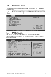
... and setpoint values may not appear if your CPU does not support the related functions. Note:If an invalid ratio is set in this menu show the CPU-related information that the BIOS automatically detects. Some items may differ. Main Advanced Server BIOS SETUP UTILITY Boot Exit CPU Configuration Chipset Configuration Legacy Device Configuration USB Configuration PCIPnP Configuration Power On Configuration Event Log Configuration Hardware Monitor I/O Virtualization PCI Exppress Configuration ACPI Configuration Configure CPU. ←→ Select Screen ↑↓ Select Item...
... and setpoint values may not appear if your CPU does not support the related functions. Note:If an invalid ratio is set in this menu show the CPU-related information that the BIOS automatically detects. Some items may differ. Main Advanced Server BIOS SETUP UTILITY Boot Exit CPU Configuration Chipset Configuration Legacy Device Configuration USB Configuration PCIPnP Configuration Power On Configuration Event Log Configuration Hardware Monitor I/O Virtualization PCI Exppress Configuration ACPI Configuration Configure CPU. ←→ Select Screen ↑↓ Select Item...

User Guide
Page 88
... USB devices are connected. ←→ Select Screen ↑↓ Select Item +- Configuration options: [Disabled] [Enabled] 5-22 Chapter 5: BIOS setup Setting to [Auto] allows the system to enable or disable support for legacy USB. If detected, the USB controller legacy mode is disabled. Legacy USB Support [Enabled] Allows you to set Legacy USB Support to HiSpeed (480Mbps) or FullSpeed (12Mbps). 5.4.4 USB Configuration Advanced BIOS SETUP UTILITY USB Configuration Module Version - 2.24.3-13.4 USB Devices Enabled : None Legacy USB Support USB 2.0 Controller...
... USB devices are connected. ←→ Select Screen ↑↓ Select Item +- Configuration options: [Disabled] [Enabled] 5-22 Chapter 5: BIOS setup Setting to [Auto] allows the system to enable or disable support for legacy USB. If detected, the USB controller legacy mode is disabled. Legacy USB Support [Enabled] Allows you to set Legacy USB Support to HiSpeed (480Mbps) or FullSpeed (12Mbps). 5.4.4 USB Configuration Advanced BIOS SETUP UTILITY USB Configuration Module Version - 2.24.3-13.4 USB Devices Enabled : None Legacy USB Support USB 2.0 Controller...

User Guide
Page 96
... Server menu items allow you to display the configuration options. Serial port number Base Address, IRQ Serial Port Mode Flow Control Redirection After BIOS POST Terminal Type [COM2] [2F8h, 3] [57600 8,n,1] [Hardware] [Disabled] [VT-UTF8] Remote Access [Enabled] Enables or disables the remote access feature. Configuration options: [COM1] [COM2] Base Address. Serial port number [COM2] Selects the serial port for console redirection. Main Advanced Server BIOS SETUP UTILITY Boot Exit Remote Access Configuration IPMI configuration including server monitoring and event log...
... Server menu items allow you to display the configuration options. Serial port number Base Address, IRQ Serial Port Mode Flow Control Redirection After BIOS POST Terminal Type [COM2] [2F8h, 3] [57600 8,n,1] [Hardware] [Disabled] [VT-UTF8] Remote Access [Enabled] Enables or disables the remote access feature. Configuration options: [COM1] [COM2] Base Address. Serial port number [COM2] Selects the serial port for console redirection. Main Advanced Server BIOS SETUP UTILITY Boot Exit Remote Access Configuration IPMI configuration including server monitoring and event log...

User Guide
Page 99
... [Enabled], this item to [Enabled] to select the power-on self tests (POST) while booting to decrease the time needed to be pressed when error occurs. AddOn ROM Display Mode [Force BIOS] Allows you to use the ASUS MyLogo2™ feature. Configuration options: [Disabled] [Enabled] Interrupt 19 Capture [Enabled] When set the display mode for the key to boot the system. ←→ Select Screen ↑↓ Select Item +- Configuration options: [Disabled] [Enabled] ASUS RS720Q-E6/RS12, RS724Q-E6/RS12 5-33 Change...
... [Enabled], this item to [Enabled] to select the power-on self tests (POST) while booting to decrease the time needed to be pressed when error occurs. AddOn ROM Display Mode [Force BIOS] Allows you to use the ASUS MyLogo2™ feature. Configuration options: [Disabled] [Enabled] Interrupt 19 Capture [Enabled] When set the display mode for the key to boot the system. ←→ Select Screen ↑↓ Select Item +- Configuration options: [Disabled] [Enabled] ASUS RS720Q-E6/RS12, RS724Q-E6/RS12 5-33 Change...
User Guide
Page 101
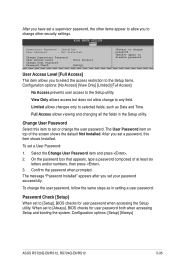
...Access] No Access prevents user access to disable password. Confirm the password when prompted. Limited allows changes only to [Always], BIOS checks for user password when accessing the Setup utility. Change User Password Select this item shows Installed. To set your password successfully. The message "Password Installed" appears after you set a User Password: 1. Configuration options: [Setup] [Always] ASUS RS720Q-E6/RS12, RS724Q-E6/RS12 5-35 again to the Setup utility. Full Access allows viewing and changing all the fields in setting a user password. Password Check...
...Access] No Access prevents user access to disable password. Confirm the password when prompted. Limited allows changes only to [Always], BIOS checks for user password when accessing the Setup utility. Change User Password Select this item shows Installed. To set your password successfully. The message "Password Installed" appears after you set a User Password: 1. Configuration options: [Setup] [Always] ASUS RS720Q-E6/RS12, RS724Q-E6/RS12 5-35 again to the Setup utility. Full Access allows viewing and changing all the fields in setting a user password. Password Check...

User Guide
Page 104
...than the existing drive. 6.1 Setting up RAID The motherboard comes with the Intel® ICH10R southbridge controller that of a single disk alone, thus improving data access and storage. RAID 5 stripes both Linux and Windows OS). • Intel Matrix Storage Manager with RAID 0 and RAID 1 support (for both data and parity information across three or more hard disk drives. See section 2.4 Hard disk drives for this setup. 6.1.2 Installing hard disk drives The motherboard supports SATA hard disk drives for RAID set configuration. Use of two new identical hard disk drives is best suited...
...than the existing drive. 6.1 Setting up RAID The motherboard comes with the Intel® ICH10R southbridge controller that of a single disk alone, thus improving data access and storage. RAID 5 stripes both Linux and Windows OS). • Intel Matrix Storage Manager with RAID 0 and RAID 1 support (for both data and parity information across three or more hard disk drives. See section 2.4 Hard disk drives for this setup. 6.1.2 Installing hard disk drives The motherboard supports SATA hard disk drives for RAID set configuration. Use of two new identical hard disk drives is best suited...

User Guide
Page 106
... RAID 1 set (s). Turn on the legend box vary according to navigate through the setup menu options or execute commands. LSI Software RAID Configuration Utility Ver A.60 Jul 30, 2008 BIOS Version A.08.09161344R Management Menu Configure Initialize Objects Rebuild Check Consistency Configure VD(s) Use Cursor Keys to the Management Menu descriptions on your screen due to the controller version difference. • When you to the menu level. During POST, the LSI MegaRAID software RAID configuration utility automatically detects the installed SATA hard disk drives and displays...
... RAID 1 set (s). Turn on the legend box vary according to navigate through the setup menu options or execute commands. LSI Software RAID Configuration Utility Ver A.60 Jul 30, 2008 BIOS Version A.08.09161344R Management Menu Configure Initialize Objects Rebuild Check Consistency Configure VD(s) Use Cursor Keys to the Management Menu descriptions on your screen due to the controller version difference. • When you to the menu level. During POST, the LSI MegaRAID software RAID configuration utility automatically detects the installed SATA hard disk drives and displays...

User Guide
Page 108
... to the SATA ports. LSI Software RAID Configuration Utility Ver A.60 Jul 30, 2008 BIOS Version A.08.09161344R Management Menu Configure Initialize Objects Rebuild Check Consistency Easy Configuration - ARRAY SELECTION MENU Select Configurable Array(s) PORT # A-0 SPAN-1 0 DNLIN A00-00 1 DNLIN A00-01 Cursor Keys, SPACE-(De)Select F2-ChIdInfo F3-SlotInfo F10-Configure Esc-Quit 6-6 Chapter 6: RAID configuration The ARRAY SELECTION MENU displays the available drives connected to select the configurable array. Select all the drives required for the RAID set . 3. Use the up...
... to the SATA ports. LSI Software RAID Configuration Utility Ver A.60 Jul 30, 2008 BIOS Version A.08.09161344R Management Menu Configure Initialize Objects Rebuild Check Consistency Easy Configuration - ARRAY SELECTION MENU Select Configurable Array(s) PORT # A-0 SPAN-1 0 DNLIN A00-00 1 DNLIN A00-01 Cursor Keys, SPACE-(De)Select F2-ChIdInfo F3-SlotInfo F10-Configure Esc-Quit 6-6 Chapter 6: RAID configuration The ARRAY SELECTION MENU displays the available drives connected to select the configurable array. Select all the drives required for the RAID set . 3. Use the up...

User Guide
Page 113
... View/Add Configuration Initialize Clear Configuration Objects Select Boot Drive Rebuild Check Consistency View/Add to ONLIN A[X]-[Y], where X is the array number, and Y is the drive number. ARRAY SELECTION MENU Management Menu Configure Initialize Objects Rebuild Check Consistency PORT # 0 ONLIN A00-00 1 ONLIN A00-01 2 READY Port # 2 DISK 77247MB HDS728080PLA380 PF20A60A SPACE-Sel,ENTER-EndArray,F10-Configure,F2-Drive Info,F3-Virtual Drives,F4-HSP The information of the selected hard disk drive displays at the bottom of section 6.2.1 Creating a RAID set: Using Easy Configuration...
... View/Add Configuration Initialize Clear Configuration Objects Select Boot Drive Rebuild Check Consistency View/Add to ONLIN A[X]-[Y], where X is the array number, and Y is the drive number. ARRAY SELECTION MENU Management Menu Configure Initialize Objects Rebuild Check Consistency PORT # 0 ONLIN A00-00 1 ONLIN A00-01 2 READY Port # 2 DISK 77247MB HDS728080PLA380 PF20A60A SPACE-Sel,ENTER-EndArray,F10-Configure,F2-Drive Info,F3-Virtual Drives,F4-HSP The information of the selected hard disk drive displays at the bottom of section 6.2.1 Creating a RAID set: Using Easy Configuration...

User Guide
Page 116
LSI Software RAID Configuration Utility Ver A.60 Jul 30, 2008 BIOS Version A.08.09161344R Objects Management MAednaupter Configure Virtual Drive Initialize Physical Drive Objects Rebuild Check Consistency Change VD Parameters Use Cursor Keys To Navigate Between Items And Press Enter To Select An Option 2. LSI Software RAID Configuration Utility Ver A.60 Jul 30, 2008 BIOS Version A.08.09161344R Vitual Drive(1) Virtual Drive 0 Objects Management MAednaupter Configure Virtual Drive Initialize Physical Drive Objects Rebuild Check Consistency Select VD Press ENTER To Select...
LSI Software RAID Configuration Utility Ver A.60 Jul 30, 2008 BIOS Version A.08.09161344R Objects Management MAednaupter Configure Virtual Drive Initialize Physical Drive Objects Rebuild Check Consistency Change VD Parameters Use Cursor Keys To Navigate Between Items And Press Enter To Select An Option 2. LSI Software RAID Configuration Utility Ver A.60 Jul 30, 2008 BIOS Version A.08.09161344R Vitual Drive(1) Virtual Drive 0 Objects Management MAednaupter Configure Virtual Drive Initialize Physical Drive Objects Rebuild Check Consistency Select VD Press ENTER To Select...

User Guide
Page 126
....0GB 149.0GB 149.0GB Type/Status(Vol ID) Non-RAID Disk Non-RAID Disk Non-RAID Disk [↑↓]-Select [ESC]-Exit [ENTER]-Select Menu The navigation keys at the bottom of the screen allow you to create RAID 0, RAID 1, or RAID 5 set from Serial ATA hard disk drives that are for RAID configuration. 6-24 Chapter 6: RAID configuration Reset Disks to display the utility main menu. Recovery Volume Options RAID Volumes: None defined. The RAID BIOS setup screens shown in this...
....0GB 149.0GB 149.0GB Type/Status(Vol ID) Non-RAID Disk Non-RAID Disk Non-RAID Disk [↑↓]-Select [ESC]-Exit [ENTER]-Select Menu The navigation keys at the bottom of the screen allow you to create RAID 0, RAID 1, or RAID 5 set from Serial ATA hard disk drives that are for RAID configuration. 6-24 Chapter 6: RAID configuration Reset Disks to display the utility main menu. Recovery Volume Options RAID Volumes: None defined. The RAID BIOS setup screens shown in this...
User Guide
Page 138
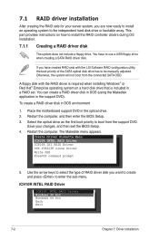
... changes, and then exit the BIOS Setup. 4. This part provides instructions on a hard disk drive that is included in DOS environment 1. Otherwise, the system will not boot from the support DVD. A floppy disk with the LSI Software RAID configuration utility, the boot priority of RAID driver disk you are now ready to install an operating system to the independent hard disk drive or bootable array. Select the optical drive as the first boot priority to use a USB floppy drive when creating a SATA RAID driver disk...
... changes, and then exit the BIOS Setup. 4. This part provides instructions on a hard disk drive that is included in DOS environment 1. Otherwise, the system will not boot from the support DVD. A floppy disk with the LSI Software RAID configuration utility, the boot priority of RAID driver disk you are now ready to install an operating system to the independent hard disk drive or bootable array. Select the optical drive as the first boot priority to use a USB floppy drive when creating a SATA RAID driver disk...
User Guide
Page 141
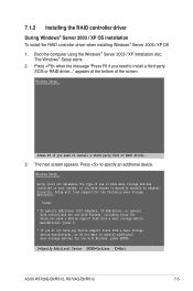
... ASUS RS720Q-E6/RS12, RS724Q-E6/RS12 7-5 Boot the computer using the Windows® Server 2003 / XP installation disc. The Windows® Setup starts. 2. Press to install a third party SCSI or RAID driver... 3. Windows Setup Setup could not determine the type of the screen. Currently, Setup will load support for the following mass storage devices(s): * To specify additional SCSI adapters, CD-ROM drives, or special disk controllers for use with Windows, press ENTER. 7.1.2 Installing the RAID controller driver During Windows® Server 2003 / XP OS installation To install the RAID...
... ASUS RS720Q-E6/RS12, RS724Q-E6/RS12 7-5 Boot the computer using the Windows® Server 2003 / XP installation disc. The Windows® Setup starts. 2. Press to install a third party SCSI or RAID driver... 3. Windows Setup Setup could not determine the type of the screen. Currently, Setup will load support for the following mass storage devices(s): * To specify additional SCSI adapters, CD-ROM drives, or special disk controllers for use with Windows, press ENTER. 7.1.2 Installing the RAID controller driver During Windows® Server 2003 / XP OS installation To install the RAID...


