

User Guide
Page 2
... use only, and are used only for any errors or inaccuracies that may appear in this manual "as a commitment by ASUS. ASUS assumes no event shall ASUS, its directors, officers, employees, or agents be liable for any indirect, special, incidental, or consequential damages (including damages for.... No part of their respective companies, and are subject to change at any time without warranty of ASUSTeK COMPUTER INC. ("ASUS"). ii Specifications and information contained in writing by any defect or error in this manual may or may be construed as is authorized in ...
... use only, and are used only for any errors or inaccuracies that may appear in this manual "as a commitment by ASUS. ASUS assumes no event shall ASUS, its directors, officers, employees, or agents be liable for any indirect, special, incidental, or consequential damages (including damages for.... No part of their respective companies, and are subject to change at any time without warranty of ASUSTeK COMPUTER INC. ("ASUS"). ii Specifications and information contained in writing by any defect or error in this manual may or may be construed as is authorized in ...

User Guide
Page 3
Contents Contents...iii Notices...vii Safety information viii About this guide ix Chapter 1: Product introduction 1.1 System package contents 1-2 1.2 Serial number label 1-2 1.3 System specifications 1-3 1.4 Front panel features 1-5 1.5 Rear panel features 1-5 1.6 Internal features 1-6 1.7 LED information 1-7 1.7.1 Front panel LEDs 1-7 1.7.2 LAN (RJ-45) LEDs 1-7 1.7.3 HDD status LED 1-8 Chapter 2: Hardware setup 2.1 Chassis cover 2-2 2.2 ...
Contents Contents...iii Notices...vii Safety information viii About this guide ix Chapter 1: Product introduction 1.1 System package contents 1-2 1.2 Serial number label 1-2 1.3 System specifications 1-3 1.4 Front panel features 1-5 1.5 Rear panel features 1-5 1.6 Internal features 1-6 1.7 LED information 1-7 1.7.1 Front panel LEDs 1-7 1.7.2 LAN (RJ-45) LEDs 1-7 1.7.3 HDD status LED 1-8 Chapter 2: Hardware setup 2.1 Chassis cover 2-2 2.2 ...
User Guide
Page 9
... regulations for different system components. Chapter 1: Product Introduction This chapter describes the general features of the server, including sections on front panel and rear panel specifications. 2. This chapter includes the motherboard layout, jumper settings, and connector locations. 5. Chapter 5: BIOS information This chapter tells how to install optional components into the barebone...
... regulations for different system components. Chapter 1: Product Introduction This chapter describes the general features of the server, including sections on front panel and rear panel specifications. 2. This chapter includes the motherboard layout, jumper settings, and connector locations. 5. Chapter 5: BIOS information This chapter tells how to install optional components into the barebone...

User Guide
Page 11
It includes sections on front panel and rear panel specifications. ASUS RS520-E6/RS8 1- Product introduction Chapter 1 This chapter describes the general features of the chassis kit.
It includes sections on front panel and rear panel specifications. ASUS RS520-E6/RS8 1- Product introduction Chapter 1 This chapter describes the general features of the chassis kit.

User Guide
Page 13
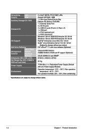
... 6 x SATA2 300MB/s ports - Model Name Processor / System Bus RS520-E6/RS8 2 x Socket LGA1366 Intel® Xeon® 5500 series processors (45nm) Quad-Core / Dual-Core Core Logic ASUS Features Smart Fan ASWM 2.0 Total Slots Memory Capacity Memory Type Memory Size... page) ASUS RS520-E6/RS8 1-3 Supports software RAID 0, 1 & 1E ASUS PIKE 1078 8-port SAS RAID card - Supports software RAID 0, 1 & 10 Optional: ASUS PIKE 1068E 8-port SAS RAID card - Intel® Matrix Storage (for Linux / Windows) - 1.3 System specifications The ASUS RS520-E6/RS8 is a server featuring the ASUS Z8NR-D12...
... 6 x SATA2 300MB/s ports - Model Name Processor / System Bus RS520-E6/RS8 2 x Socket LGA1366 Intel® Xeon® 5500 series processors (45nm) Quad-Core / Dual-Core Core Logic ASUS Features Smart Fan ASWM 2.0 Total Slots Memory Capacity Memory Type Memory Size... page) ASUS RS520-E6/RS8 1-3 Supports software RAID 0, 1 & 1E ASUS PIKE 1078 8-port SAS RAID card - Supports software RAID 0, 1 & 10 Optional: ASUS PIKE 1068E 8-port SAS RAID card - Intel® Matrix Storage (for Linux / Windows) - 1.3 System specifications The ASUS RS520-E6/RS8 is a server featuring the ASUS Z8NR-D12...
User Guide
Page 14
... (Subject to change without any notice) CA® eTrust™ 7.1 anti-virus software (Optional) Onboard IPMI Solution ASMB4-iKVM for KVM-over-IP support (Optional) ASUS ASWM 2.0 and SNMP® 615mm x 444mm x 87mm 22 Kg 770W (80+) 1+1 Redundant Power Supply (Default with one Power Supply Module) Operation temperature: 10°C ~ 35...
... (Subject to change without any notice) CA® eTrust™ 7.1 anti-virus software (Optional) Onboard IPMI Solution ASMB4-iKVM for KVM-over-IP support (Optional) ASUS ASWM 2.0 and SNMP® 615mm x 444mm x 87mm 22 Kg 770W (80+) 1+1 Redundant Power Supply (Default with one Power Supply Module) Operation temperature: 10°C ~ 35...

User Guide
Page 55
ASUS RS520-E6/RS8 4-11 USB connectors (10-1 pin USB34, USB56; 4-pin USB7) The USB34 and USB56 connectors are for a A-type internal USB 2.0 device. 5. Serial General Purpose Input/Output ... chassis. Connect the USB module cable to the connectors, and then install the module to 480 Mbps connection speed. The USB connectors comply with USB 2.0 specification that controls the LED pattern generation, device information and general purpose data. The USB port module is for USB 2.0 ports. The USB7 connector is purchased...
ASUS RS520-E6/RS8 4-11 USB connectors (10-1 pin USB34, USB56; 4-pin USB7) The USB34 and USB56 connectors are for a A-type internal USB 2.0 device. 5. Serial General Purpose Input/Output ... chassis. Connect the USB module cable to the connectors, and then install the module to 480 Mbps connection speed. The USB connectors comply with USB 2.0 specification that controls the LED pattern generation, device information and general purpose data. The USB port module is for USB 2.0 ports. The USB7 connector is purchased...

User Guide
Page 67
...) on the menu bar have their respective menu items. 5.2.5 Sub-menu items A solid triangle before each item on the menu bar displays the specific items for that item. 5.2.8 Scroll bar A scroll bar appears on the right side of options. Advanced BIOS SETUP UTILITY CPU Bridge Chipset Configuration USB...Up/ Down arrow keys or / keys to display a list of a menu screen when there are items that do not fit on the screen. ASUS RS520-E6/RS8 5-7 For example, selecting Main shows the Main menu items. The other items on the screen. Scroll bar Pop-up window with the configuration options ...
...) on the menu bar have their respective menu items. 5.2.5 Sub-menu items A solid triangle before each item on the menu bar displays the specific items for that item. 5.2.8 Scroll bar A scroll bar appears on the right side of options. Advanced BIOS SETUP UTILITY CPU Bridge Chipset Configuration USB...Up/ Down arrow keys or / keys to display a list of a menu screen when there are items that do not fit on the screen. ASUS RS520-E6/RS8 5-7 For example, selecting Main shows the Main menu items. The other items on the screen. Scroll bar Pop-up window with the configuration options ...
User Guide
Page 69
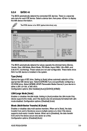
... set to [Auto], the data transfer from and to the device occurs multiple sectors at a time. Configuration options: [Disabled] [Auto] ASUS RS520-E6/RS8 5-9 Main BIOS SETUP UTILITY SATA 1 Device :Hard Disk Vendor :ST3160812AS Size :160.0GB LBA Mode :Supported Block Mode:16Sectors PIO Mode ... S.M.A.R.T. Configuration options: [Disabled] [Auto] Block (Multi-Sector Transfer) M [Auto] Enables or disables data multi-sectors transfers. These values are specifically configuring a CD-ROM drive. These items show N/A if no IDE device is either a ZIP, LS-120, or MO drive. Setting to ...
... set to [Auto], the data transfer from and to the device occurs multiple sectors at a time. Configuration options: [Disabled] [Auto] ASUS RS520-E6/RS8 5-9 Main BIOS SETUP UTILITY SATA 1 Device :Hard Disk Vendor :ST3160812AS Size :160.0GB LBA Mode :Supported Block Mode:16Sectors PIO Mode ... S.M.A.R.T. Configuration options: [Disabled] [Auto] Block (Multi-Sector Transfer) M [Auto] Enables or disables data multi-sectors transfers. These values are specifically configuring a CD-ROM drive. These items show N/A if no IDE device is either a ZIP, LS-120, or MO drive. Setting to ...

User Guide
Page 73
... Configuration BIOS SETUP UTILITY CPU1/2 Memory Configuration Allows you an overview of installed memory (6 DIMMs per CPU). ASUS RS520-E6/RS8 5-13 The BIOS automatically detects the items in this menu. Processor Displays the auto-detected CPU specification. System Memory Information Displays system memory information. System Memory Displays the auto-detected system memory. 5.3.7 System Information...
... Configuration BIOS SETUP UTILITY CPU1/2 Memory Configuration Allows you an overview of installed memory (6 DIMMs per CPU). ASUS RS520-E6/RS8 5-13 The BIOS automatically detects the items in this menu. Processor Displays the auto-detected CPU specification. System Memory Information Displays system memory information. System Memory Displays the auto-detected system memory. 5.3.7 System Information...

User Guide
Page 78
...] [Enabled] CSI L1 [Disabled] Configuration options: [Disabled] [Enabled] Memory Frequency [Auto] You may allow the system to detect DDR3 memory frequency via SPD or designate a specific frequency. Configuration options: [Slow-Mode] [Full-Speed] CSI Frequency [Auto] Allows you to set the CSI frequency. Configuration options: [Independent] [Channel Mirroring] [Lockstep] [Sparing] Memory...
...] [Enabled] CSI L1 [Disabled] Configuration options: [Disabled] [Enabled] Memory Frequency [Auto] You may allow the system to detect DDR3 memory frequency via SPD or designate a specific frequency. Configuration options: [Slow-Mode] [Full-Speed] CSI Frequency [Auto] Allows you to set the CSI frequency. Configuration options: [Independent] [Channel Mirroring] [Lockstep] [Sparing] Memory...

User Guide
Page 86
... UTILITY Advanced ACPI Configuration ACPI 2.0 Support ACPI APIC support BIOS-->AML ACPI table Headless mode [Enabled] [Enabled] [Enabled] [Disabled] Add additional tables as per ACPI 2.0 specifications. ACPI 2.0 Support [Enabled] Specifies the Advanced Configuration and Power Interface (ACPI) version supported. Configuration options: [Disabled] [Enabled] Headless mode [Disabled] Allows you to include the...
... UTILITY Advanced ACPI Configuration ACPI 2.0 Support ACPI APIC support BIOS-->AML ACPI table Headless mode [Enabled] [Enabled] [Enabled] [Disabled] Add additional tables as per ACPI 2.0 specifications. ACPI 2.0 Support [Enabled] Specifies the Advanced Configuration and Power Interface (ACPI) version supported. Configuration options: [Disabled] [Enabled] Headless mode [Disabled] Allows you to include the...

User Guide
Page 125
... 3. From the View menu, select Advanced Mode to "Normal". When finished, the status is changed to display the details of the same specification into the same SATA Port. From the Volumes view option, select RAID volume to load the Intel Matrix Stroage Manager utility. 6. You may...and reboot the system. 5. Remove the failed SATA hard disk and install a new SATA hard disk of the Intel Matrix Storage Console. 7. ASUS RS520-E6/RS8 6-31 Select Start > Programs > Intel Matrix Storage > Intel Matrix Storage Console or click the Intel Matrix Storage Manager tray icon to view ...
... 3. From the View menu, select Advanced Mode to "Normal". When finished, the status is changed to display the details of the same specification into the same SATA Port. From the Volumes view option, select RAID volume to load the Intel Matrix Stroage Manager utility. 6. You may...and reboot the system. 5. Remove the failed SATA hard disk and install a new SATA hard disk of the Intel Matrix Storage Console. 7. ASUS RS520-E6/RS8 6-31 Select Start > Programs > Intel Matrix Storage > Intel Matrix Storage Console or click the Intel Matrix Storage Manager tray icon to view ...