User Guide
Page 9
... provides instructions for installing the necessary drivers for disposal of the crossed out wheeled bin indicates that you have to install optional components into the barebone server. 4. This symbol of electronic products. Check local regulations for different system components. Chapter 2: Hardware setup This chapter lists the hardware setup procedures that the...
... provides instructions for installing the necessary drivers for disposal of the crossed out wheeled bin indicates that you have to install optional components into the barebone server. 4. This symbol of electronic products. Check local regulations for different system components. Chapter 2: Hardware setup This chapter lists the hardware setup procedures that the...

User Guide
Page 15
... the I/O shield with easily accessible features. ASUS RS520-E6/RS8 1-5 The power and reset buttons, LED indicators, optical drive, and two USB ports are located on the rear panel if motherboard is not present. • *The port is for ASUS ASMB4-iKVM controller card only. 1.4 Front panel features The barebone server displays a simple yet stylish front...
... the I/O shield with easily accessible features. ASUS RS520-E6/RS8 1-5 The power and reset buttons, LED indicators, optical drive, and two USB ports are located on the rear panel if motherboard is not present. • *The port is for ASUS ASMB4-iKVM controller card only. 1.4 Front panel features The barebone server displays a simple yet stylish front...
User Guide
Page 16
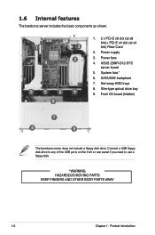
Hot-swap HDD trays 5 5 5 5 8. Front I/O board (hidden) 6 7 8 9 The barebone server does not include a floppy disk drive. Connect a USB floppy disk drive to any of the USB ports on the front or rear panel ...disk. *WARNING HAZARDOUS MOVING PARTS KEEP FINGERS AND OTHER BODY PARTS AWAY 1-6 Chapter 1: Product introduction Power fans 4. ASUS Z8NR-D12-SYS server board 5. System fans* 6. Slim-type optical drive bay 9. Power supply 4 2 3. 1.6 Internal features The barebone server includes the basic components as shown. 1. 2 x PCI-E x8 slot (at x8 link)+ PCI-E x4 ...
Hot-swap HDD trays 5 5 5 5 8. Front I/O board (hidden) 6 7 8 9 The barebone server does not include a floppy disk drive. Connect a USB floppy disk drive to any of the USB ports on the front or rear panel ...disk. *WARNING HAZARDOUS MOVING PARTS KEEP FINGERS AND OTHER BODY PARTS AWAY 1-6 Chapter 1: Product introduction Power fans 4. ASUS Z8NR-D12-SYS server board 5. System fans* 6. Slim-type optical drive bay 9. Power supply 4 2 3. 1.6 Internal features The barebone server includes the basic components as shown. 1. 2 x PCI-E x8 slot (at x8 link)+ PCI-E x4 ...

User Guide
Page 41
Installation options Chapter 3 This chapter describes how to install the optional components and devices into the barebone server. ASUS RS520-E6/RS8 2-
Installation options Chapter 3 This chapter describes how to install the optional components and devices into the barebone server. ASUS RS520-E6/RS8 2-

User Guide
Page 43
3. Repeat steps 1 to 4 to attach the second server rail to install the barebone server. 2. Measure the rack rail when assembled to ensure that the front end of the rack rail goes to the front of space (2U) on .... 9. Attach the rear end of the server rail to the holes on the rack where you want to the other side of the rack rails. 5. ASUS RS520-E6/RS8 3-3 Install the nuts on the holes of the two hooks to the side of the chassis, matching each of the 2U space on the holes...
3. Repeat steps 1 to 4 to attach the second server rail to install the barebone server. 2. Measure the rack rail when assembled to ensure that the front end of the rack rail goes to the front of space (2U) on .... 9. Attach the rear end of the server rail to the holes on the rack where you want to the other side of the rack rails. 5. ASUS RS520-E6/RS8 3-3 Install the nuts on the holes of the two hooks to the side of the chassis, matching each of the 2U space on the holes...