

User Guide
Page 11
It includes sections on front panel and rear panel specifications. ASUS RS520-E6/RS8 1- Product introduction Chapter 1 This chapter describes the general features of the chassis kit.
It includes sections on front panel and rear panel specifications. ASUS RS520-E6/RS8 1- Product introduction Chapter 1 This chapter describes the general features of the chassis kit.

User Guide
Page 13
... Slot Type QPI 4.8 / 5.86 / 6.4 GT/s Intel® 5500 I = Internal A or S will be hot-swappable 8 x Hot-swap 3.5" SAS/SATA HDD Bays (continued on the next page) ASUS RS520-E6/RS8 1-3 Supports hardware RAID 0, 1, 10, 5 & 6 HDD Bays I /O Hub Intel® ICH10R √ √ 12 (3-channel per CPU, 6 DIMMs per CPU) Maximum up to 96GB (RDIMM) Maximum...
... Slot Type QPI 4.8 / 5.86 / 6.4 GT/s Intel® 5500 I = Internal A or S will be hot-swappable 8 x Hot-swap 3.5" SAS/SATA HDD Bays (continued on the next page) ASUS RS520-E6/RS8 1-3 Supports hardware RAID 0, 1, 10, 5 & 6 HDD Bays I /O Hub Intel® ICH10R √ √ 12 (3-channel per CPU, 6 DIMMs per CPU) Maximum up to 96GB (RDIMM) Maximum...

User Guide
Page 15
...-iKVM controller card only. The middle part includes the I/O shield with easily accessible features. ASUS RS520-E6/RS8 1-5 1.4 Front panel features The barebone server displays a simple yet stylish front panel with openings for the rear panel connectors on the motherboard. 3 Expansion slots LAN ...
...-iKVM controller card only. The middle part includes the I/O shield with easily accessible features. ASUS RS520-E6/RS8 1-5 1.4 Front panel features The barebone server displays a simple yet stylish front panel with openings for the rear panel connectors on the motherboard. 3 Expansion slots LAN ...

User Guide
Page 17
... Status Description OFF No link GREEN Linked BLINKING Data activity SPEED LED Status Description OFF 10 Mbps connection ORANGE 100 Mbps connection GREEN 1 Gbps connection ASUS RS520-E6/RS8 1-7
... Status Description OFF No link GREEN Linked BLINKING Data activity SPEED LED Status Description OFF 10 Mbps connection ORANGE 100 Mbps connection GREEN 1 Gbps connection ASUS RS520-E6/RS8 1-7

User Guide
Page 19
Hardware setup Chapter 2 This chapter lists the hardware setup procedures that you have to perform when installing or removing system components. ASUS RS520-E6/RS8 2-
Hardware setup Chapter 2 This chapter lists the hardware setup procedures that you have to perform when installing or removing system components. ASUS RS520-E6/RS8 2-

User Guide
Page 21
... Dual/Quad Core processor. • Your boxed Intel® Xeon® LGA1366 processor package should come with the cap on the motherboard. ASUS will shoulder the cost of repair only if the damage is on the socket and the socket contacts are not bent. Locate the CPU socket... incorrect removal of the motherboard, ensure that the socket box is facing towards you see any damage to the PnP cap/socket contacts/motherboard components. ASUS RS520-E6/RS8 2-3 If the instructions in this section do not match the CPU documentation, follow the latter. • Upon purchase of the PnP cap. ...
... Dual/Quad Core processor. • Your boxed Intel® Xeon® LGA1366 processor package should come with the cap on the motherboard. ASUS will shoulder the cost of repair only if the damage is on the socket and the socket contacts are not bent. Locate the CPU socket... incorrect removal of the motherboard, ensure that the socket box is facing towards you see any damage to the PnP cap/socket contacts/motherboard components. ASUS RS520-E6/RS8 2-3 If the instructions in this section do not match the CPU documentation, follow the latter. • Upon purchase of the PnP cap. ...

User Guide
Page 23
... into the socket to the exposed area of the socket, and then fit the socket alignment key into your eyes or touches your finger directly. 8. A ASUS RS520-E6/RS8 B 2-5 If so, skip this step. Close the load plate (A), and then push the load lever (B) until it off immediately and seek professional medical help. Apply...
... into the socket to the exposed area of the socket, and then fit the socket alignment key into your eyes or touches your finger directly. 8. A ASUS RS520-E6/RS8 B 2-5 If so, skip this step. Close the load plate (A), and then push the load lever (B) until it off immediately and seek professional medical help. Apply...

User Guide
Page 25
ASUS RS520-E6/RS8 2-7 The figure illustrates the location of the DDR3 DIMM sockets: Recommended CPU1 memory configuration Mode Sockets DIMM_C1 DIMM_C2 DIMM_B1 DIMM_B2 2 DIMMs 3 DIMMs 4 DIMMs 6 DIMMs Populated ...
ASUS RS520-E6/RS8 2-7 The figure illustrates the location of the DDR3 DIMM sockets: Recommended CPU1 memory configuration Mode Sockets DIMM_C1 DIMM_C2 DIMM_B1 DIMM_B2 2 DIMMs 3 DIMMs 4 DIMMs 6 DIMMs Populated ...

User Guide
Page 27
... Retaining Clip 2.3.4 Removing a DIMM Follow these steps to unlock the DIMM. 1 1 DIMM notch Support the DIMM lightly with your fingers when pressing the retaining clips. ASUS RS520-E6/RS8 2-9 Align a DIMM on the socket such that it flips out with a notch so that the notch on the DIMM matches the break on the socket...
... Retaining Clip 2.3.4 Removing a DIMM Follow these steps to unlock the DIMM. 1 1 DIMM notch Support the DIMM lightly with your fingers when pressing the retaining clips. ASUS RS520-E6/RS8 2-9 Align a DIMM on the socket such that it flips out with a notch so that the notch on the DIMM matches the break on the socket...

User Guide
Page 29
ASUS RS520-E6/RS8 2-11 Repeat steps 1 to 6 if you wish to the SATAII/ SAS interface on the backplane. 6. The drive tray is correctly placed when its front edge aligns with the bay edge. 7. When installed, the SATAII/SAS connector on the drive connects to install a second SATAII/SAS drive. 5. Push the tray lever until it all the way to the depth of the bay until just a small fraction of the tray edge protrudes. Carefully insert the drive tray and push it clicks, and secures the drive tray in place.
ASUS RS520-E6/RS8 2-11 Repeat steps 1 to 6 if you wish to the SATAII/ SAS interface on the backplane. 6. The drive tray is correctly placed when its front edge aligns with the bay edge. 7. When installed, the SATAII/SAS connector on the drive connects to install a second SATAII/SAS drive. 5. Push the tray lever until it all the way to the depth of the bay until just a small fraction of the tray edge protrudes. Carefully insert the drive tray and push it clicks, and secures the drive tray in place.
User Guide
Page 31
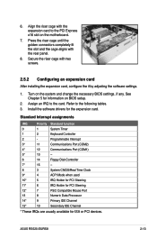
ASUS RS520-E6/RS8 2-13 Turn on BIOS setup. 2. Install the software drivers for ISA or PCI devices. See Chapter 5 for information on the system and change the necessary ...
ASUS RS520-E6/RS8 2-13 Turn on BIOS setup. 2. Install the software drivers for ISA or PCI devices. See Chapter 5 for information on the system and change the necessary ...

User Guide
Page 33
2.7 SATAII/SAS backplane cabling Connects a 8-pin plug from power supply Connects the data cables connected to the motherboard SGPIO_SEL jumper: pins 1-2 (Onboard) pins 2-3 (Add-on card) ASUS RS520-E6/RS8 2-15
2.7 SATAII/SAS backplane cabling Connects a 8-pin plug from power supply Connects the data cables connected to the motherboard SGPIO_SEL jumper: pins 1-2 (Onboard) pins 2-3 (Add-on card) ASUS RS520-E6/RS8 2-15

User Guide
Page 35
Insert the slim optical drive into the drive bay. 4. ASUS RS520-E6/RS8 2-17 Remove the two screws to the depth of the bay until it clicks in the optical dirve tray, and then secure it in place. Take out the optional optical drive from its package. 2.8.2 Optical drive (optional) To install the slim optical drive: 1. Push the slim optical drive all the way to release the dummy covor for the optical drive bay. 2. Place it with four screws. 3.
Insert the slim optical drive into the drive bay. 4. ASUS RS520-E6/RS8 2-17 Remove the two screws to the depth of the bay until it clicks in the optical dirve tray, and then secure it in place. Take out the optional optical drive from its package. 2.8.2 Optical drive (optional) To install the slim optical drive: 1. Push the slim optical drive all the way to release the dummy covor for the optical drive bay. 2. Place it with four screws. 3.

User Guide
Page 37
ASUS RS520-E6/RS8 2-19 Take out the seocond redundant power supply module from its package. Firmly pull the lever to slide the power supply module into the chassis. 3. Remove the redundant power supply dummy cover. 2. Slide it into the chassis. 2.8.3 Redundant power supply module To install a second redundant power supply module: 1.
ASUS RS520-E6/RS8 2-19 Take out the seocond redundant power supply module from its package. Firmly pull the lever to slide the power supply module into the chassis. 3. Remove the redundant power supply dummy cover. 2. Slide it into the chassis. 2.8.3 Redundant power supply module To install a second redundant power supply module: 1.

User Guide
Page 39
Connect the data cables, by numerial order, to the SAS connectors on the motherboard. 6. Locate the I Button in place. Set the SGPIO_SEL1 jumper on the backplane to pin 2-3 when connecting data cables to the SAS connectors labeled SAS1-4 (red) on the motherboard. ASUS RS520-E6/RS8 2-21 5. Snap the I Button slot on your motherboard. 1. Installing i Button (for PIKE 1078 only) Follow the steps below to install an optional i Button on the motherboard. 2.
Connect the data cables, by numerial order, to the SAS connectors on the motherboard. 6. Locate the I Button in place. Set the SGPIO_SEL1 jumper on the backplane to pin 2-3 when connecting data cables to the SAS connectors labeled SAS1-4 (red) on the motherboard. ASUS RS520-E6/RS8 2-21 5. Snap the I Button slot on your motherboard. 1. Installing i Button (for PIKE 1078 only) Follow the steps below to install an optional i Button on the motherboard. 2.

User Guide
Page 41
Installation options Chapter 3 This chapter describes how to install the optional components and devices into the barebone server. ASUS RS520-E6/RS8 2-
Installation options Chapter 3 This chapter describes how to install the optional components and devices into the barebone server. ASUS RS520-E6/RS8 2-

User Guide
Page 43
.... 4. Repeat steps 5 to 8 to the 2U space on the corresponding rack rear. 4. Then slide the rail toward the front panel until it fits the rack. 6. ASUS RS520-E6/RS8 3-3 Select two units of the rack space. 7. Secure the front end of the rail with two rack screws. 9. Secure the rear end of the rail...
.... 4. Repeat steps 5 to 8 to the 2U space on the corresponding rack rear. 4. Then slide the rail toward the front panel until it fits the rack. 6. ASUS RS520-E6/RS8 3-3 Select two units of the rack space. 7. Secure the front end of the rail with two rack screws. 9. Secure the rear end of the rail...

User Guide
Page 45
ASUS RS520-E6/RS8 3- 4-1 Motherboard info Chapter 4 This chapter includes the motherboard layout, and brief descriptions of the jumpers and internal connectors.
ASUS RS520-E6/RS8 3- 4-1 Motherboard info Chapter 4 This chapter includes the motherboard layout, and brief descriptions of the jumpers and internal connectors.

User Guide
Page 47
... fan connectors (4-pin CPU_FAN1/2, REAR_FAN1/2, FRNT_FAN1/2/3/4) 8. Auxiliary panel connector (20-pin AUX_PANEL1 [black]) Page 4-9 4-9 4-10 4-10 4-11 4-11 4-12 4-12 4-13 4-13 4-14 4-15 4-16 ASUS RS520-E6/RS8 4-3 IPMI setting (3-in IPMI_SEL1) 8, Fan controller setting (3-pin FAN_SEL1) 9. SSI power connectors (24-pin ATXPWR1, 8-pin ATX12V1/2) 12. DDR3 voltage setting (4-pin LVDDR3_SEL1/2) Page 4-4 4-5 4-5 4-6 4-6 4-7 4-7 4-8 4-8 Internal...
... fan connectors (4-pin CPU_FAN1/2, REAR_FAN1/2, FRNT_FAN1/2/3/4) 8. Auxiliary panel connector (20-pin AUX_PANEL1 [black]) Page 4-9 4-9 4-10 4-10 4-11 4-11 4-12 4-12 4-13 4-13 4-14 4-15 4-16 ASUS RS520-E6/RS8 4-3 IPMI setting (3-in IPMI_SEL1) 8, Fan controller setting (3-pin FAN_SEL1) 9. SSI power connectors (24-pin ATXPWR1, 8-pin ATX12V1/2) 12. DDR3 voltage setting (4-pin LVDDR3_SEL1/2) Page 4-4 4-5 4-5 4-6 4-6 4-7 4-7 4-8 4-8 Internal...

User Guide
Page 49
Set to pins 1-2 to activate the Gigabit LAN feature. Set to pins 1-2 to activate the VGA feature. 3. LAN controller setting (3-pin LAN_SW1, LAN_SW2) These jumpers allow you to enable or disable the onboard Intel® WG82574L Gigabit LAN1/2 controller. 2. VGA controller setting (3-pin VGA_SW1) This jumper allows you to enable or disable the onboard VGA controller. ASUS RS520-E6/RS8 4-5
Set to pins 1-2 to activate the Gigabit LAN feature. Set to pins 1-2 to activate the VGA feature. 3. LAN controller setting (3-pin LAN_SW1, LAN_SW2) These jumpers allow you to enable or disable the onboard Intel® WG82574L Gigabit LAN1/2 controller. 2. VGA controller setting (3-pin VGA_SW1) This jumper allows you to enable or disable the onboard VGA controller. ASUS RS520-E6/RS8 4-5


