Asus RS500A-E10-RS4 Support and Manuals
Get Help and Manuals for this Asus item
View All Support Options Below
Free Asus RS500A-E10-RS4 manuals!
Problems with Asus RS500A-E10-RS4?
Ask a Question
Free Asus RS500A-E10-RS4 manuals!
Problems with Asus RS500A-E10-RS4?
Ask a Question
Popular Asus RS500A-E10-RS4 Manual Pages
RS500A-E10 Series User Manual - Page 4
...E10-RS4 / RS500A-E10-PS4 only 2-37
Chapter 3:
Installation Options
3.1 Rail kit installation 3-2 3.1.1 Tool-less Friction Rail Kit 3-2 3.1.2 Installing the tool-less rack rail 3-2
3.2 Rail kit dimensions 3-5
Chapter 4:
Motherboard Information
4.1 Motherboard layout 4-2 4.2 Jumpers...4-4 4.3 Onboard LEDs 4-8 4.4 Internal connectors 4-11
Chapter 5: BIOS Setup
5.1 Managing and updating...
RS500A-E10 Series User Manual - Page 12
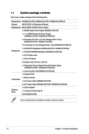
... for the following items.
Model Name RS500A-E10-PS4, RS500A-E10-RS4, RS500A-E10-RS12U
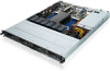
Chassis
ASUS R10E 1U Rackmount Chassis
Motherboard ASUS KRPA-U16/SYS Server Board
1 x 650W Single Power Supply (RS500A-E10-PS4)
1 x 1 +1 650W Redundant Power Supply (RS500A-E10-RS4, RS500A-E10-RS12U)
4 x Hot-swap 3.5-inch or 2.5-inch Storage Device Trays (RS500A-E10-PS4, RS500A-E10-RS4)
12 x Hot-swap...
RS500A-E10 Series User Manual - Page 14
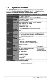
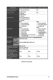
...SATA/ SAS/NVMe Supported)
1 x Management port
Networking LAN
Optional OCP Adapter: - 2 or 4 x 1G port
- 2x 10G port - 2x 25G port or higher bandwidth
Graphic VGA
Aspeed AST2500 64MB
(continued on the next page)
1-4
Chapter 1: Product Introduction ASUS PIKE II 3008 8-port SAS HBA Card
Controller
SAS Controller -
Model Name
RS500A-E10-PS4 RS500A-E10-RS4 RS500A-E10-RS12U
Processor...
RS500A-E10 Series User Manual - Page 15
...Support Software
RS500A-E10-PS4 RS500A-E10-RS4 RS500A-E10-RS12U
1 x Slim-type Optical Drive
N/A
2 x USB 3.0 ports N/A
1 x VGA port 2 x USB 3.0 ports
1 x VGA port
2 x RJ-45 1GbE LAN ports
1 x RJ-45 Management port
1 x COM port Rear:
Rear:
- 1 x Power Switch/LED
- 1 x P ower Switch/LED
- 1 x Q-Code/Port 80 LED
- 1 x Q -Code... OS support from http://www.asus.com/
ASUS Control Center...
RS500A-E10 Series User Manual - Page 17

... screw
Bay 2
Bay 4
Bay 6
Bay 8
Asset tag
Power button
Power LED Message LED Location LED
2
1
LAN 1 LED LAN 2 LED
ASUS RS500A-E10 Series
1-7
Refer to the Front panel LEDs section for the LED descriptions. RS500A-E10-RS4 / RS500A-E10-PS4
Rack screw
Bay 1
Bay 2
Bay 3
Rack screw Bay 4
Optical drive (optional)
4
3
2
1
Asset tag (hidden)
LAN 4 LED LAN 3 LED...
RS500A-E10 Series User Manual - Page 18
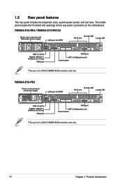
... 1: Product Introduction RS500A-E10-RS4 / RS500A-E10-RS12U
Power cord connector and Redundant power supply
LAN port for iKVM*
Q-Code LED
PCI-E slot
Locate LED
USB 3.0 ports Gigabit LAN port 1 (bottom) and 2 (top)
VGA port
COM port OCP 2.0 Mezzanine slot Power button
*This port is for ASUS ASMB9-iKVM controller card only.
The middle part includes the I/O shield...
RS500A-E10 Series User Manual - Page 19
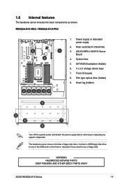
... features
The barebone server includes the basic components as shown. SATA/SAS backplane (hidden) 6. 4 x 3.5" storage device bays 7.
WARNING HAZARDOUS MOVING PARTS KEEP FINGERS AND OTHER BODY PARTS AWAY
ASUS RS500A-E10 Series
1-9 RS500A-E10-RS4 / RS500A-E10-PS4
1. Connect a USB floppy disk drive to use a floppy disk. System fans 5. The barebone server does not include a floppy disk drive...
RS500A-E10 Series User Manual - Page 21
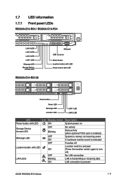
... LAN connection is normal; 1.7 LED information 1.7.1 Front panel LEDs
RS500A-E10-RS4 / RS500A-E10-PS4
4
3
2
1
LAN 4 LED LAN 3 LED
LAN 2 LED
LAN 1 LED
Message LED
Storage Device Access LED
RS500A-E10-RS12U
VGA port
USB 3.0 ports
Reset button Location button with LED...power on
No activity Data activity (when optional PIKE card is installed) System is present
ASUS RS500A-E10 Series
1-11
RS500A-E10 Series User Manual - Page 23
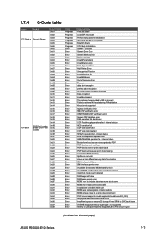
... be 0x400_0000) No physical x86 cores were found on the next page)
ASUS RS500A-E10 Series
1-13 Success Generic Error Code Generic Memory Error Buffer Overflow Invalid Parameter(s) Invalid Data Length Data Alignment Error Null Pointer Error Unsupported Function Invalid Service ID Invalid Address Out of Resource Error Timeout data abort exception prefetch abort exception Out of free SRAM to...
RS500A-E10 Series User Manual - Page 29
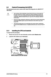
...; 7002 Series.
• Upon purchase of repair only if the damage is missing, or if you see the section Chassis cover.
2. 2.2 Central Processing Unit (CPU)
The motherboard comes with the cap on your retailer immediately if the PnP cap is shipment/ transit-related.
• Keep the cap after installing the motherboard. ASUS RS500A-E10 Series
2-3
RS500A-E10 Series User Manual - Page 33
... DIMMs in this section.
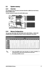
2.3 System memory
2.3.1 Overview
The motherboard comes with the same CAS latency. ASUS RS500A-E10 Series
2-7 The figure illustrates the location of the DDR4 DIMM sockets:
2.3.2 Memory Configurations
You may install 32GB, 16GB, 8GB, 4GB RDIMM, 64GB, 32GB LRDIMM, or 128GB, 64GB LRDIMM 3DS into the DIMM sockets using the memory...
RS500A-E10 Series User Manual - Page 35
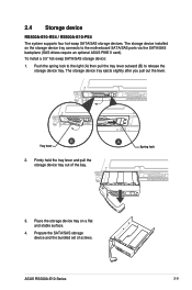
... tray on the storage device tray connects to release the storage device tray. ASUS RS500A-E10 Series
2-9 Firmly hold the tray lever and pull the storage device tray out of screws.
Spring lock
3. The storage device installed on a flat and stable surface.
4. 2.4 Storage device
RS500A-E10-RS4 / RS500A-E10-PS4 The system supports four hot-swap SATA/SAS storage devices.
RS500A-E10 Series User Manual - Page 57
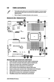
...cables unless you will remove pre‑installed components to install additional devices.
• Refer to...RS4 / RS500A-E10-PS4
Standard cables connected to the motherboard 1. 24-pin ATX power connector (from power supply to motherboard) 2. 8-pin 12V power connector (from motherboard to front I /O board) 7. System auxiliary panel connector (from power supply to power board)
ASUS RS500A-E10...
RS500A-E10 Series User Manual - Page 59
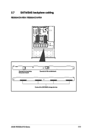
2.7 SATA/SAS backplane cabling
RS500A-E10-RS4 / RS500A-E10-PS4
Connects to 8-pin plug from power board
Connects to the motherboard
Connect the SATA/SAS storage devices
ASUS RS500A-E10 Series
2-33
RS500A-E10 Series User Manual - Page 63
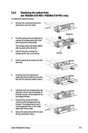
... pull the tray lever outward (B). ASUS RS500A-E10 Series
2-37 Carefully insert the replacement optical disk drive module into the drive bay until just a small fraction of the bay until it is correctly placed when its front edge aligns with the screw that secures the optical drive and set it clicks, and secure the storage...
Asus RS500A-E10-RS4 Reviews
We have not received any reviews for Asus yet.