User Guide
Page 11
It includes sections on front panel and rear panel specifications. ASUS RS500-E6/PS4 1- Product introduction Chapter 1 This chapter describes the general features of the chassis kit.
It includes sections on front panel and rear panel specifications. ASUS RS500-E6/PS4 1- Product introduction Chapter 1 This chapter describes the general features of the chassis kit.

User Guide
Page 12
.... See the figure below. 1.1 System package contents Check your system package for the following items. Model Name Chassis Motherboard Component Accessories Optional Items RS500-E6/PS4 ASUS R10A 1U Rackmount Chassis ASUS Z8NR-D12-SYS Server Board 1 x 600W 80+ Single Power Supply 1 x SATAII/SAS HDD Backplane (BP4LX-R10A) 4 x hot-swap HDD trays (varies by territories...
.... See the figure below. 1.1 System package contents Check your system package for the following items. Model Name Chassis Motherboard Component Accessories Optional Items RS500-E6/PS4 ASUS R10A 1U Rackmount Chassis ASUS Z8NR-D12-SYS Server Board 1 x 600W 80+ Single Power Supply 1 x SATAII/SAS HDD Backplane (BP4LX-R10A) 4 x hot-swap HDD trays (varies by territories...
User Guide
Page 13
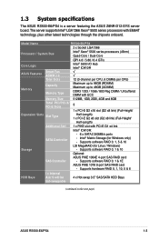
... LSI MegaRAID (for Windows only) - Model Name Processor / System Bus RS500-E6/PS4 2 x Socket LGA1366 Intel® Xeon® 5500 series processors (45nm) Quad-Core / Dual-Core Core Logic ASUS Features Memory Smart Fan ASWM 2.0 Total Slots Capacity Memory Type Memory Size ... be hot-swappable 4 x Hot-swap 3.5" SAS/SATA HDD Bays (continued on the next page) ASUS RS500-E6/PS4 1-3 Supports software RAID 0, 1 & 10 Optional: ASUS PIKE 1064E 4-port SAS RAID card - Supports software RAID 0, 1 & 1E ASUS PIKE 1078 8-port SAS RAID card - Supports hardware RAID 0, 1, 10, 5 & 6 HDD Bays...
... LSI MegaRAID (for Windows only) - Model Name Processor / System Bus RS500-E6/PS4 2 x Socket LGA1366 Intel® Xeon® 5500 series processors (45nm) Quad-Core / Dual-Core Core Logic ASUS Features Memory Smart Fan ASWM 2.0 Total Slots Capacity Memory Type Memory Size ... be hot-swappable 4 x Hot-swap 3.5" SAS/SATA HDD Bays (continued on the next page) ASUS RS500-E6/PS4 1-3 Supports software RAID 0, 1 & 10 Optional: ASUS PIKE 1064E 4-port SAS RAID card - Supports software RAID 0, 1 & 1E ASUS PIKE 1078 8-port SAS RAID card - Supports hardware RAID 0, 1, 10, 5 & 6 HDD Bays...
User Guide
Page 15
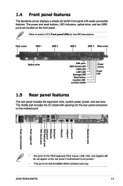
... PS/2 keyboard, PS/2 mouse, USB, VGA, and Gigabit LAN do not appear on the motherboard. The middle part includes the I/O shield with easily accessible features. ASUS RS500-E6/PS4 1-5 Rack screw HDD 1 HDD 2 HDD 3 HDD 4 Rack screw Optical drive USB ports HDD Access LED LAN2 LED LAN1 LED Message LED Reset button Location LED... yet stylish front panel with openings for the rear panel connectors on the rear panel if motherboard is not present. • *The port is for ASUS ASMB4-iKVM controller card only.
... PS/2 keyboard, PS/2 mouse, USB, VGA, and Gigabit LAN do not appear on the motherboard. The middle part includes the I/O shield with easily accessible features. ASUS RS500-E6/PS4 1-5 Rack screw HDD 1 HDD 2 HDD 3 HDD 4 Rack screw Optical drive USB ports HDD Access LED LAN2 LED LAN1 LED Message LED Reset button Location LED... yet stylish front panel with openings for the rear panel connectors on the rear panel if motherboard is not present. • *The port is for ASUS ASMB4-iKVM controller card only.
User Guide
Page 17
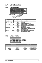
... Status Description OFF No link GREEN Linked BLINKING Data activity SPEED LED Status Description OFF 10 Mbps connection ORANGE 100 Mbps connection GREEN 1 Gbps connection ASUS RS500-E6/PS4 1-7 no incoming event ASWM indicates a HW monitor event Normal status Location switch is pressed (Press the location switch again to turn off) No LAN connection...
... Status Description OFF No link GREEN Linked BLINKING Data activity SPEED LED Status Description OFF 10 Mbps connection ORANGE 100 Mbps connection GREEN 1 Gbps connection ASUS RS500-E6/PS4 1-7 no incoming event ASWM indicates a HW monitor event Normal status Location switch is pressed (Press the location switch again to turn off) No LAN connection...
User Guide
Page 19
Hardware setup Chapter 2 This chapter lists the hardware setup procedures that you have to perform when installing or removing system components. ASUS RS500-E6/PS4 2-
Hardware setup Chapter 2 This chapter lists the hardware setup procedures that you have to perform when installing or removing system components. ASUS RS500-E6/PS4 2-
User Guide
Page 21
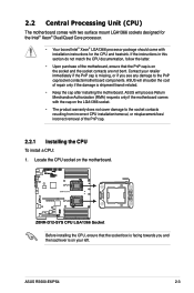
...boxed Intel® Xeon® LGA1366 processor package should come with the cap on the socket and the socket contacts are not bent. ASUS RS500-E6/PS4 2-3 ASUS will shoulder the cost of repair only if the damage is on the motherboard. If the instructions in this section do not match the...documentation, follow the latter. • Upon purchase of the PnP cap. 2.2.1 Installing the CPU To install a CPU: 1. Contact your left. ASUS will process Return Merchandise Authorization (RMA) requests only if the motherboard comes with installation instructions for the CPU and heatsink.
...boxed Intel® Xeon® LGA1366 processor package should come with the cap on the socket and the socket contacts are not bent. ASUS RS500-E6/PS4 2-3 ASUS will shoulder the cost of repair only if the damage is on the motherboard. If the instructions in this section do not match the...documentation, follow the latter. • Upon purchase of the PnP cap. 2.2.1 Installing the CPU To install a CPU: 1. Contact your left. ASUS will process Return Merchandise Authorization (RMA) requests only if the motherboard comes with installation instructions for the CPU and heatsink.
User Guide
Page 23
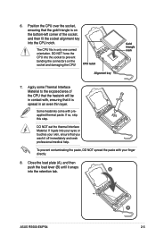
... NOT force the CPU into the socket to the exposed area of the socket, and then fit the socket alignment key into the CPU notch. A ASUS RS500-E6/PS4 B 2-5 Apply some Thermal Interface Material to prevent bending the connectors on the bottom‑left corner of the CPU that the heatsink will be in...
... NOT force the CPU into the socket to the exposed area of the socket, and then fit the socket alignment key into the CPU notch. A ASUS RS500-E6/PS4 B 2-5 Apply some Thermal Interface Material to prevent bending the connectors on the bottom‑left corner of the CPU that the heatsink will be in...
User Guide
Page 25
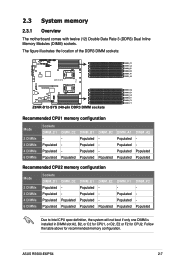
... boot if only one DIMM is installed in DIMM slot A2, B2, or C2 for CPU1, or D2, E2 or F2 for recommended memory configuration. ASUS RS500-E6/PS4 2-7
... boot if only one DIMM is installed in DIMM slot A2, B2, or C2 for CPU1, or D2, E2 or F2 for recommended memory configuration. ASUS RS500-E6/PS4 2-7
User Guide
Page 27
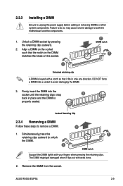
... clips outward. 2. Firmly insert the DIMM into a socket to avoid damaging the DIMM. 3. Remove the DIMM from the socket. 2.3.3 Installing a DIMM Ensure to remove a DIMM. 2 1. ASUS RS500-E6/PS4 2-9
... clips outward. 2. Firmly insert the DIMM into a socket to avoid damaging the DIMM. 3. Remove the DIMM from the socket. 2.3.3 Installing a DIMM Ensure to remove a DIMM. 2 1. ASUS RS500-E6/PS4 2-9
User Guide
Page 29
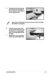
Push the tray lever until it all the way to the depth of the bay until just a small fraction of the tray edge protrudes. The drive tray is correctly placed when its front edge aligns with the bay edge. 7. Carefully insert the drive tray and push it clicks, and secures the drive tray in place. Repeat steps 1 to 6 if you wish to the SATAII/ SAS interface on the drive connects to install a second SATAII/SAS drive. ASUS RS500-E6/PS4 2-11 When installed, the SATAII/SAS connector on the backplane. 6. 5.
Push the tray lever until it all the way to the depth of the bay until just a small fraction of the tray edge protrudes. The drive tray is correctly placed when its front edge aligns with the bay edge. 7. Carefully insert the drive tray and push it clicks, and secures the drive tray in place. Repeat steps 1 to 6 if you wish to the SATAII/ SAS interface on the drive connects to install a second SATAII/SAS drive. ASUS RS500-E6/PS4 2-11 When installed, the SATAII/SAS connector on the backplane. 6. 5.
User Guide
Page 31
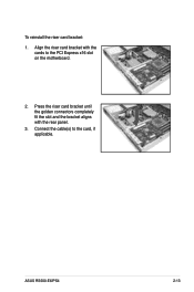
Connect the cable(s) to the PCI Express x16 slot on the motherboard. 2. Align the riser card bracket with the rear panel. 3. Press the riser card bracket until the golden connectors completely fit the slot and the bracket aligns with the cards to the card, if applicable. ASUS RS500-E6/PS4 2-13 To reinstall the riser card bracket: 1.
Connect the cable(s) to the PCI Express x16 slot on the motherboard. 2. Align the riser card bracket with the rear panel. 3. Press the riser card bracket until the golden connectors completely fit the slot and the bracket aligns with the cards to the card, if applicable. ASUS RS500-E6/PS4 2-13 To reinstall the riser card bracket: 1.
User Guide
Page 33
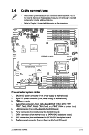
... SATAII/SAS backplane board) 8. System fan connectors (from motherboard to front I /O board) 7. SAS connectors (from motherboard to motherboard) 3. Panel connector (from motherboard to front I/O board) ASUS RS500-E6/PS4 2-15 Auxiliary panel connector (from power supply to front I /O board) 6. 2.6 Cable connections • The bundled system cables are pre-connected before shipment. You do not...
... SATAII/SAS backplane board) 8. System fan connectors (from motherboard to front I /O board) 7. SAS connectors (from motherboard to motherboard) 3. Panel connector (from motherboard to front I/O board) ASUS RS500-E6/PS4 2-15 Auxiliary panel connector (from power supply to front I /O board) 6. 2.6 Cable connections • The bundled system cables are pre-connected before shipment. You do not...
User Guide
Page 35
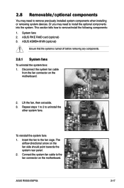
2.8 Removable/optional components You may need to remove previously installed system components when installing or removing system devices. ASUS ASMB4-iKVM (optional) Ensure that the system is turned off before removing any components. 2.8.1 System fans To uninstall the system fans: 1. ... to 2 to the fan cage. Connect the system fan cable to remove/install the following components: 1. The airflow directional arrow on the motherboard. 2. ASUS RS500-E6/PS4 2-17 Lift the fan, then set aside. 3. This section tells how to the fan connector on the motherboard. System fans...
2.8 Removable/optional components You may need to remove previously installed system components when installing or removing system devices. ASUS ASMB4-iKVM (optional) Ensure that the system is turned off before removing any components. 2.8.1 System fans To uninstall the system fans: 1. ... to 2 to the fan cage. Connect the system fan cable to remove/install the following components: 1. The airflow directional arrow on the motherboard. 2. ASUS RS500-E6/PS4 2-17 Lift the fan, then set aside. 3. This section tells how to the fan connector on the motherboard. System fans...
User Guide
Page 37
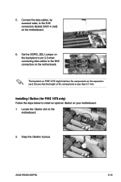
Ensure that the height of the components is less than 6.7 mm. Snap the I Button slot on the motherboard. 2. ASUS RS500-E6/PS4 2-19 Set the SGPIO_SEL1 jumper on the backplane to pin 2-3 when connecting data cables to the SAS connectors labeled SAS1-4 (red) on the motherboard. Connect ...
Ensure that the height of the components is less than 6.7 mm. Snap the I Button slot on the motherboard. 2. ASUS RS500-E6/PS4 2-19 Set the SGPIO_SEL1 jumper on the backplane to pin 2-3 when connecting data cables to the SAS connectors labeled SAS1-4 (red) on the motherboard. Connect ...
User Guide
Page 39
ASUS RS500-E6/PS4 2- Installation options Chapter 3 This chapter describes how to install the optional components and devices into the barebone server.
ASUS RS500-E6/PS4 2- Installation options Chapter 3 This chapter describes how to install the optional components and devices into the barebone server.
User Guide
Page 41
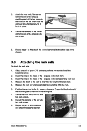
...) on the rail. Measure the depth of the rack to the side of the chassis with one unit of the rail with two rack screws. 9. ASUS RS500-E6/PS4 3-3 Then slide the rail toward the front panel until it fits the rack. 6. Secure the rear end of the server rail to determine the length...
...) on the rail. Measure the depth of the rack to the side of the chassis with one unit of the rail with two rack screws. 9. ASUS RS500-E6/PS4 3-3 Then slide the rail toward the front panel until it fits the rack. 6. Secure the rear end of the server rail to determine the length...
User Guide
Page 43
Motherboard info Chapter 4 This chapter includes the motherboard layout, and brief descriptions of the jumpers and internal connectors. ASUS RS500-E6/PS4 3- 4-1
Motherboard info Chapter 4 This chapter includes the motherboard layout, and brief descriptions of the jumpers and internal connectors. ASUS RS500-E6/PS4 3- 4-1
User Guide
Page 45
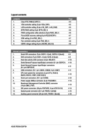
... (10-1 pin USB34, USB56; 4-pin USB7) 7. Auxiliary panel connector (20-pin AUX_PANEL1 [black]) Page 4-9 4-9 4-10 4-10 4-11 4-11 4-12 4-12 4-13 4-13 4-14 4-15 4-16 ASUS RS500-E6/PS4 4-3
... (10-1 pin USB34, USB56; 4-pin USB7) 7. Auxiliary panel connector (20-pin AUX_PANEL1 [black]) Page 4-9 4-9 4-10 4-10 4-11 4-11 4-12 4-12 4-13 4-13 4-14 4-15 4-16 ASUS RS500-E6/PS4 4-3
User Guide
Page 47
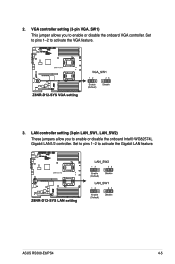
Set to pins 1-2 to activate the Gigabit LAN feature. Set to pins 1-2 to activate the VGA feature. 3. VGA controller setting (3-pin VGA_SW1) This jumper allows you to enable or disable the onboard VGA controller. ASUS RS500-E6/PS4 4-5 LAN controller setting (3-pin LAN_SW1, LAN_SW2) These jumpers allow you to enable or disable the onboard Intel® WG82574L Gigabit LAN1/2 controller. 2.
Set to pins 1-2 to activate the Gigabit LAN feature. Set to pins 1-2 to activate the VGA feature. 3. VGA controller setting (3-pin VGA_SW1) This jumper allows you to enable or disable the onboard VGA controller. ASUS RS500-E6/PS4 4-5 LAN controller setting (3-pin LAN_SW1, LAN_SW2) These jumpers allow you to enable or disable the onboard Intel® WG82574L Gigabit LAN1/2 controller. 2.