
User Guide
Page 4
... 4-2 4.2 Jumpers 4-4 4.3 Connectors 4-9 Chapter 5: BIOS setup 5.1 Managing and updating your BIOS 5-2 5.1.1 Creating a bootable floppy disk 5-2 5.1.2 AFUDOS utility 5-3 5.1.3 ASUS CrashFree BIOS 2 utility 5-6 5.1.4 ASUS Update utility 5-8 5.2 BIOS setup program 5-11 5.2.1 BIOS menu screen 5-12 5.2.2 Menu bar 5-12 5.2.3 Navigation keys 5-12 5.2.4 Menu items 5-13 5.2.5 Sub-menu items 5-13 5.2.6 Configuration fields 5-13 5.2.7 Pop-up window 5-13 5.2.8 Scroll bar...
... 4-2 4.2 Jumpers 4-4 4.3 Connectors 4-9 Chapter 5: BIOS setup 5.1 Managing and updating your BIOS 5-2 5.1.1 Creating a bootable floppy disk 5-2 5.1.2 AFUDOS utility 5-3 5.1.3 ASUS CrashFree BIOS 2 utility 5-6 5.1.4 ASUS Update utility 5-8 5.2 BIOS setup program 5-11 5.2.1 BIOS menu screen 5-12 5.2.2 Menu bar 5-12 5.2.3 Navigation keys 5-12 5.2.4 Menu items 5-13 5.2.5 Sub-menu items 5-13 5.2.6 Configuration fields 5-13 5.2.7 Pop-up window 5-13 5.2.8 Scroll bar...
User Guide
Page 10
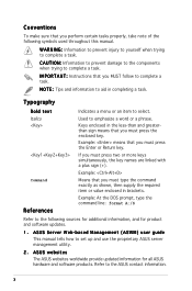
...ASUS websites The ASUS websites worldwide provide updated information for product and software updates. 1. Refer to aid in completing a task. x C A U T I N G : Information to prevent injury to yourself when trying to complete a task. Used to complete a task. Conventions To make sure that you MUST follow to complete a task. Keys... supply the required item or value enclosed in the less-than and greaterthan sign means that you must press two or more keys simultaneously, the key names are linked with a plus sign (+). W A R N I O N : Information to prevent damage to the ...
...ASUS websites The ASUS websites worldwide provide updated information for product and software updates. 1. Refer to aid in completing a task. x C A U T I N G : Information to prevent injury to yourself when trying to complete a task. Used to complete a task. Conventions To make sure that you MUST follow to complete a task. Keys... supply the required item or value enclosed in the less-than and greaterthan sign means that you must press two or more keys simultaneously, the key names are linked with a plus sign (+). W A R N I O N : Information to prevent damage to the ...
User Guide
Page 22
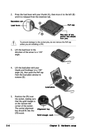
... that the gold triangle is on the bottom-left (B) until it is released from the load plate window to a 135º angle. 4. The socket alignment A l i g n m e n t k e y key should face you are installing a CPU. 3. To prevent damage to the left corner of the arrow to remove (B). Lift the load lever in the direction...
... that the gold triangle is on the bottom-left (B) until it is released from the load plate window to a 135º angle. 4. The socket alignment A l i g n m e n t k e y key should face you are installing a CPU. 3. To prevent damage to the left corner of the arrow to remove (B). Lift the load lever in the direction...
User Guide
Page 26
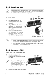
... DIMM might get damaged when it fits in place and the DIMM is properly seated. 2 3 DDR2 DIMM notch Unlocked retaining clip • A DDR2 DIMM is keyed with your fingers when pressing the retaining clips. Remove the DIMM from the socket. 2 1 DDR2 DIMM notch 2-10 Chapter 2: Hardware setup Align a DIMM on the...
... DIMM might get damaged when it fits in place and the DIMM is properly seated. 2 3 DDR2 DIMM notch Unlocked retaining clip • A DDR2 DIMM is keyed with your fingers when pressing the retaining clips. Remove the DIMM from the socket. 2 1 DDR2 DIMM notch 2-10 Chapter 2: Hardware setup Align a DIMM on the...
User Guide
Page 52
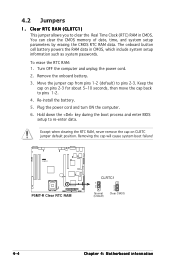
...the cap back to re-enter data. To erase the RTC RAM: 1. Removing the cap will cause system boot failure! ® P5MT-R P5MT-R Clear RTC RAM CLRTC1 1 2 Normal (Default) 2 3 Clear CMOS 4-4 Chapter 4: Motherboard information Clear RTC RAM (CLRTC1) This jumper allows you to pins 2-3. You can clear... battery. 3. Move the jumper cap from pins 1-2 (default) to clear the Real Time Clock (RTC) RAM in CMOS, which include system setup information such as system passwords. Hold down the key during the boot process and enter BIOS setup to pins 1-2. 4. 4.2 Jumpers 1. Re-install the battery. ...
...the cap back to re-enter data. To erase the RTC RAM: 1. Removing the cap will cause system boot failure! ® P5MT-R P5MT-R Clear RTC RAM CLRTC1 1 2 Normal (Default) 2 3 Clear CMOS 4-4 Chapter 4: Motherboard information Clear RTC RAM (CLRTC1) This jumper allows you to pins 2-3. You can clear... battery. 3. Move the jumper cap from pins 1-2 (default) to clear the Real Time Clock (RTC) RAM in CMOS, which include system setup information such as system passwords. Hold down the key during the boot process and enter BIOS setup to pins 1-2. 4. 4.2 Jumpers 1. Re-install the battery. ...
User Guide
Page 53
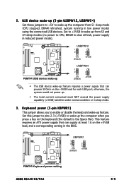
... refreshed, system running in the BIOS. ® P5MT-R KBPWR1 1 2 +5V (Default) 2 3 +5VSB P5MT-R Keyboard power setting ASUS RS120-E3/PA4 4-5 Keyboard power (3-pin KBPWR1) This jumper allows you to wake up the computer when you press a key on the keyboard (the default is the Space Bar). This feature requires an ATX power supply that...
... refreshed, system running in the BIOS. ® P5MT-R KBPWR1 1 2 +5V (Default) 2 3 +5VSB P5MT-R Keyboard power setting ASUS RS120-E3/PA4 4-5 Keyboard power (3-pin KBPWR1) This jumper allows you to wake up the computer when you press a key on the keyboard (the default is the Space Bar). This feature requires an ATX power supply that...
User Guide
Page 77
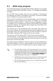
...update using the navigation keys. • The default BIOS settings for this motherboard apply for most conditions to ensure system compatibility and stability. When you start up the computer, the system provides you with its test routines. ASUS RS120-E3/PA4 5-11 This ...asus.com) to reconfigure your system using this program. You can also restart by pressing the reset button on your BIOS." Do this motherboard. 5.2 BIOS setup program This motherboard supports a programmable firmware chip that the computer can recognize these changes and record them in the CMOS RAM...
...update using the navigation keys. • The default BIOS settings for this motherboard apply for most conditions to ensure system compatibility and stability. When you start up the computer, the system provides you with its test routines. ASUS RS120-E3/PA4 5-11 This ...asus.com) to reconfigure your system using this program. You can also restart by pressing the reset button on your BIOS." Do this motherboard. 5.2 BIOS setup program This motherboard supports a programmable firmware chip that the computer can recognize these changes and record them in the CMOS RAM...
User Guide
Page 78
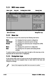
... v02.57 (C)Copyright 1985-2004, American Megatrends, Inc. Use the navigation keys to select a field. Some of a menu screen are the navigation keys for that particular menu. Select Screen Select Item +- Sub-menu items Navigation keys 5.2.2 Menu bar The menu bar on top of the screen has the ...settings To select an item on the menu bar, press the right or left arrow key on the keyboard until the desired item is highlighted. 5.2.3 Navigation keys At the bottom right corner of the navigation keys differ from one screen to configure system time. 5.2.1 BIOS menu screen Menu items ...
... v02.57 (C)Copyright 1985-2004, American Megatrends, Inc. Use the navigation keys to select a field. Some of a menu screen are the navigation keys for that particular menu. Select Screen Select Item +- Sub-menu items Navigation keys 5.2.2 Menu bar The menu bar on top of the screen has the ...settings To select an item on the menu bar, press the right or left arrow key on the keyboard until the desired item is highlighted. 5.2.3 Navigation keys At the bottom right corner of the navigation keys differ from one screen to configure system time. 5.2.1 BIOS menu screen Menu items ...
User Guide
Page 79
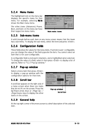
... screen. You cannot select an item that is a brief description of the menu screen is not user-configurable. Press the Up/Down arrow keys or / keys to display a list of the field opposite the item. Change Option F1 General Help F10 Save and Exit ESC Exit Pop-up window with...there are items that do not fit on any menu screen means that menu. Select Screen Select Item +- To change the value of options. ASUS RS120-E3/PA4 5-13 Advanced APM Configuration Power Management/APM Video Power Down Mode Hard Disk Power Down Mode Suspend Time Out(Minute) Throttle Slow Clock Ratio...
... screen. You cannot select an item that is a brief description of the menu screen is not user-configurable. Press the Up/Down arrow keys or / keys to display a list of the field opposite the item. Change Option F1 General Help F10 Save and Exit ESC Exit Pop-up window with...there are items that do not fit on any menu screen means that menu. Select Screen Select Item +- To change the value of options. ASUS RS120-E3/PA4 5-13 Advanced APM Configuration Power Management/APM Video Power Down Mode Hard Disk Power Down Mode Suspend Time Out(Minute) Throttle Slow Clock Ratio...
User Guide
Page 86
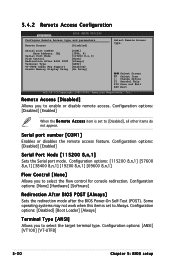
... and parameters Remote Access [Disabled] Serial port number Base Address, IRQ Serial Port Mode Flow Control Redirection After BIOS POST Terminal Type VT-UTFB Combo Key Support Sredir Memory Display Delay [COM1] [3F8h, 4] [115200 8,n,1] [None] [Always] [ANSI] [Enabled] [No Delay] Select Remote Access type...
... and parameters Remote Access [Disabled] Serial port number Base Address, IRQ Serial Port Mode Flow Control Redirection After BIOS POST Terminal Type VT-UTFB Combo Key Support Sredir Memory Display Delay [COM1] [3F8h, 4] [115200 8,n,1] [None] [Always] [ANSI] [Enabled] [No Delay] Select Remote Access type...
User Guide
Page 87
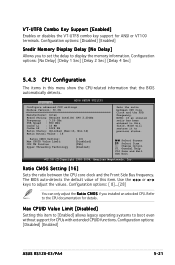
... General Help F10 Save and Exit ESC Exit v02.58 (C)Copyright 1985-2004, American Megatrends, Inc. Configuration options: [Disabled] [Enabled] ASUS RS120-E3/PA4 5-21 Use the < + > or < - > keys to the CPU documentation for details. Configuration options: [ 8]...[28] You can only adjust the R a t i o C M O...the FSB Frequency. Max CPUID Value Limit [Disabled] Setting this item. VT-UTF8 Combo Key Support [Enabled] Enables or disables the VT-UTF8 combo key support for CPUs with extended CPUID functions. Advanced BIOS SETUP UTILITY Configure advanced CPU settings ...
... General Help F10 Save and Exit ESC Exit v02.58 (C)Copyright 1985-2004, American Megatrends, Inc. Configuration options: [Disabled] [Enabled] ASUS RS120-E3/PA4 5-21 Use the < + > or < - > keys to the CPU documentation for details. Configuration options: [ 8]...[28] You can only adjust the R a t i o C M O...the FSB Frequency. Max CPUID Value Limit [Disabled] Setting this item. VT-UTF8 Combo Key Support [Enabled] Enables or disables the VT-UTF8 combo key support for CPUs with extended CPUID functions. Advanced BIOS SETUP UTILITY Configure advanced CPU settings ...
User Guide
Page 98
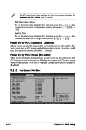
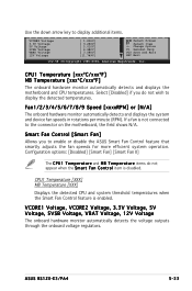
...provides at least 1A on the system. RTC Alarm Date (Days) To set the alarm date, highlight this item and press the or key to turn on the +5VSB lead. This feature requires an ATX power supply that provides at least 1A on the system. Fan1 Speed Fan2... Speed Fan3 Speed Fan4 Speed Fan5 Speed Fan6 Speed Fan7 Speed Fan8 Speed Fan9 Speed Smart Fan Control CPU1 Temperature MB Temperature VCORE1 Voltage [8411RPM] [8169RPM] [7594RPM] [7133RPM] [7573RPM] [7336RPM] [7317RPM] [7520RPM] [8598RPM] [Smart Fan II] [061] [050] [ 1.332V] Select Screen Select Item +-...
...provides at least 1A on the system. RTC Alarm Date (Days) To set the alarm date, highlight this item and press the or key to turn on the +5VSB lead. This feature requires an ATX power supply that provides at least 1A on the system. Fan1 Speed Fan2... Speed Fan3 Speed Fan4 Speed Fan5 Speed Fan6 Speed Fan7 Speed Fan8 Speed Fan9 Speed Smart Fan Control CPU1 Temperature MB Temperature VCORE1 Voltage [8411RPM] [8169RPM] [7594RPM] [7133RPM] [7573RPM] [7336RPM] [7317RPM] [7520RPM] [8598RPM] [Smart Fan II] [061] [050] [ 1.332V] Select Screen Select Item +-...
User Guide
Page 99
... General Help F10 Save and Exit ESC Exit v02.58 (C)Copyright 1985-2004, American Megatrends, Inc. ASUS RS120-E3/PA4 5-33 CPU1 Temperature [xxxºC/xxxºF] MB Temperature [xxxºC/xxxºF] The onboard hardware monitor automatically detects and displays the motherboard and CPU ...appear when the S m a r t F a n C o n t r o l item is disabled. Use the down arrow key to the connector on the motherboard, the field shows N/A. CPU1 Temperature [XXX] MB Temperature [XXX] Displays the detected CPU and system threshold temperatures when the Smart Fan Control feature is not connected...
... General Help F10 Save and Exit ESC Exit v02.58 (C)Copyright 1985-2004, American Megatrends, Inc. ASUS RS120-E3/PA4 5-33 CPU1 Temperature [xxxºC/xxxºF] MB Temperature [xxxºC/xxxºF] The onboard hardware monitor automatically detects and displays the motherboard and CPU ...appear when the S m a r t F a n C o n t r o l item is disabled. Use the down arrow key to the connector on the motherboard, the field shows N/A. CPU1 Temperature [XXX] MB Temperature [XXX] Displays the detected CPU and system threshold temperatures when the Smart Fan Control feature is not connected...
User Guide
Page 101
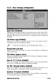
Configuration options: [Disabled] [Enabled] [Auto] Wait for the F1 key to trap Interrupt 19. Configuration options: [Disabled] [Enabled] Interrupt 19 Capture [Enabled] When set to Enabled, the system waits for 'F1' If Error [Enabled] When ... (POST) while booting to decrease the time needed to boot the system. Bootup Num-Lock [On] Allows you to use the ASUS MyLogo2™ feature. Configuration options: [Disabled] [Enabled] ASUS RS120-E3/PA4 5-35 Change Option F1 General Help F10 Save and Exit ESC Exit v02.58 (C)Copyright 1985-2004, American Megatrends, Inc. Configuration...
Configuration options: [Disabled] [Enabled] [Auto] Wait for the F1 key to trap Interrupt 19. Configuration options: [Disabled] [Enabled] Interrupt 19 Capture [Enabled] When set to Enabled, the system waits for 'F1' If Error [Enabled] When ... (POST) while booting to decrease the time needed to boot the system. Bootup Num-Lock [On] Allows you to use the ASUS MyLogo2™ feature. Configuration options: [Disabled] [Enabled] ASUS RS120-E3/PA4 5-35 Change Option F1 General Help F10 Save and Exit ESC Exit v02.58 (C)Copyright 1985-2004, American Megatrends, Inc. Configuration...
User Guide
Page 105
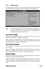
... your changes or cancel the command. If you wish to cancel the command, select [Cancel] then press to return to the Exit menu. ASUS RS120-E3/PA4 5-39 F10 key can be used for the BIOS items, and save or discard your changes and exit Setup. A confirmation window appears and prompts you to either...
... your changes or cancel the command. If you wish to cancel the command, select [Cancel] then press to return to the Exit menu. ASUS RS120-E3/PA4 5-39 F10 key can be used for the BIOS items, and save or discard your changes and exit Setup. A confirmation window appears and prompts you to either...
User Guide
Page 110
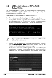
...: 1. Refer to navigate through the setup menu options or execute commands. Use the arrow keys to RAID Mode is the legend box. The keys on the legend box allow you to create RAID 0, RAID 1, or RAID 10 set (s). The keys on the system after installing all the SATA hard disk drives. 2. Turn on...
...: 1. Refer to navigate through the setup menu options or execute commands. Use the arrow keys to RAID Mode is the legend box. The keys on the legend box allow you to create RAID 0, RAID 1, or RAID 10 set (s). The keys on the system after installing all the SATA hard disk drives. 2. Turn on...
User Guide
Page 111
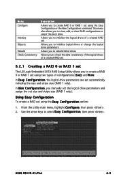
...Easy Configuration or the New Configuration command. From the utility main menu, highlight C o n f i g u r e, then press . 2. Use the arrow keys to create a RAID 0 or RAID 1 set size and stripe size (RAID 1 only). This menu also allows you to view, add, or clear RAID ...drive parameters and assign the set using the E a s y C o n f i g u r a t i o n option: 1. In N e w C o n f i g u r a t i o n, you to select Easy Configuration, then press . ASUS RS120-E3/PA4 6-5 Using Easy Configuration To create a RAID set using two types of configurations: E a s y and N e w.
...Easy Configuration or the New Configuration command. From the utility main menu, highlight C o n f i g u r e, then press . 2. Use the arrow keys to create a RAID 0 or RAID 1 set size and stripe size (RAID 1 only). This menu also allows you to view, add, or clear RAID ...drive parameters and assign the set using the E a s y C o n f i g u r a t i o n option: 1. In N e w C o n f i g u r a t i o n, you to select Easy Configuration, then press . ASUS RS120-E3/PA4 6-5 Using Easy Configuration To create a RAID set using two types of configurations: E a s y and N e w.
User Guide
Page 114
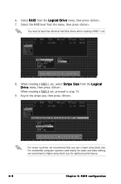
... at least two identical hard disk drives when creating a RAID 1 set , proceed to step 10. 9. When creating a RAID 1 set, select S t r i p e S i z e from the L o g i c a l D r i v e menu, then press . 6. Key-in the stripe size, then press .
... at least two identical hard disk drives when creating a RAID 1 set , proceed to step 10. 9. When creating a RAID 1 set, select S t r i p e S i z e from the L o g i c a l D r i v e menu, then press . 6. Key-in the stripe size, then press .
User Guide
Page 116
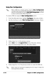
Using New Configuration When a RAID set is already existing, using the N e w C o n f i g u r a t i o n option: 1. Use the arrow keys to initiate the fresh logical drive manually. 6-10 Chapter 6: RAID configuration Key-in the desired logical drive size, then press . 6. Before using, we recommend completing the 6.2.4 steps to select N e w C o n f i g u r a t i o n, then press . 3. Select S i z e from the L o g i c a l D r i v e menu, then press...
Using New Configuration When a RAID set is already existing, using the N e w C o n f i g u r a t i o n option: 1. Use the arrow keys to initiate the fresh logical drive manually. 6-10 Chapter 6: RAID configuration Key-in the desired logical drive size, then press . 6. Before using, we recommend completing the 6.2.4 steps to select N e w C o n f i g u r a t i o n, then press . 3. Select S i z e from the L o g i c a l D r i v e menu, then press...
User Guide
Page 117
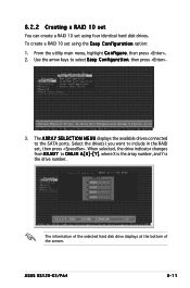
ASUS RS120-E3/PA4 6-11 6.2.2 Creating a RAID 10 set You can create a RAID 10 set using four identical hard disk drives. From the utility main menu, highlight C o n f i g u r e, then ... of the screen. To create a RAID 10 set using the E a s y C o n f i g u r a t i o n option: 1. Select the drive(s) you want to select Easy Configuration, then press . 3. Use the arrow keys to include in the RAID set, then press .
ASUS RS120-E3/PA4 6-11 6.2.2 Creating a RAID 10 set You can create a RAID 10 set using four identical hard disk drives. From the utility main menu, highlight C o n f i g u r e, then ... of the screen. To create a RAID 10 set using the E a s y C o n f i g u r a t i o n option: 1. Select the drive(s) you want to select Easy Configuration, then press . 3. Use the arrow keys to include in the RAID set, then press .
