User Guide
Page 5
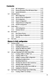
... Settings Configuration 5-35 5.6.3 Security 5-36 5.7 Exit menu 5-39 Chapter 6: RAID configuration 6.1 Setting up RAID 6-2 6.1.1 RAID definitions 6-2 6.1.2 Installing hard disk drives 6-3 6.1.3 Setting the RAID item in BIOS 6-3 6.1.4 RAID configuration utility 6-3 6.2 LSI Logic Embedded SATA RAID Setup Utility 6-4 6.2.1 Creating a RAID 0 or RAID 1 set 6-5 6.2.2 Creating a RAID 10 set 6-11 6.2.3 Adding or viewing a RAID configuration 6-15 6.2.4 Initializing the logical drives 6-18 6.2.5 Rebuilding failed drives...
... Settings Configuration 5-35 5.6.3 Security 5-36 5.7 Exit menu 5-39 Chapter 6: RAID configuration 6.1 Setting up RAID 6-2 6.1.1 RAID definitions 6-2 6.1.2 Installing hard disk drives 6-3 6.1.3 Setting the RAID item in BIOS 6-3 6.1.4 RAID configuration utility 6-3 6.2 LSI Logic Embedded SATA RAID Setup Utility 6-4 6.2.1 Creating a RAID 0 or RAID 1 set 6-5 6.2.2 Creating a RAID 10 set 6-11 6.2.3 Adding or viewing a RAID configuration 6-15 6.2.4 Initializing the logical drives 6-18 6.2.5 Rebuilding failed drives...
User Guide
Page 6
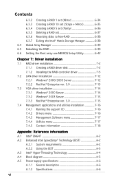
... 6.3.7 Exiting the Intel® Matrix Storage Manager 6-38 6.4 Global Array Manager 6-39 6.5 Rebuilding the RAID 6-39 6.6 Setting the Boot array use MB BIOS Setup Utility 6-42 Chapter 7: Driver installation 7.1 RAID driver installation 7-2 7.1.1 Creating a RAID driver disk 7-2 7.1.2 Installing the RAID controller driver 7-3 7.2 LAN driver installation 7-12 7.2.1 Windows® 2000/2003 Server 7-12 7.2.2 Red Hat® Enterprise...
... 6.3.7 Exiting the Intel® Matrix Storage Manager 6-38 6.4 Global Array Manager 6-39 6.5 Rebuilding the RAID 6-39 6.6 Setting the Boot array use MB BIOS Setup Utility 6-42 Chapter 7: Driver installation 7.1 RAID driver installation 7-2 7.1.1 Creating a RAID driver disk 7-2 7.1.2 Installing the RAID controller driver 7-3 7.2 LAN driver installation 7-12 7.2.1 Windows® 2000/2003 Server 7-12 7.2.2 Red Hat® Enterprise...

User Guide
Page 9
... and describes the BIOS parameters. 6. Chapter 2: Hardware setup This chapter lists the hardware setup procedures that you may refer to when configuring the motherboard. Chapter 6: RAID configuration This chapter tells how to perform when installing or removing system components. 3. Contents This guide contains the following parts: 1. Chapter 4: Motherboard information This chapter...
... and describes the BIOS parameters. 6. Chapter 2: Hardware setup This chapter lists the hardware setup procedures that you may refer to when configuring the motherboard. Chapter 6: RAID configuration This chapter tells how to perform when installing or removing system components. 3. Contents This guide contains the following parts: 1. Chapter 4: Motherboard information This chapter...
User Guide
Page 12
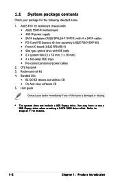
Bundled CDs • RS120-E3 drivers and utilities CD • CA Anti-virus software CD 5. Refer to use a USB floppy drive when creating a SATA RAID driver disk. CPU heatsink 3. You may have to Chapter 7 for the following standard items. 1. User guide Contact your package for details. 1-2 Chapter 1: Product introduction Rackmount rail kit 4. ASUS R10 1U...
Bundled CDs • RS120-E3 drivers and utilities CD • CA Anti-virus software CD 5. Refer to use a USB floppy drive when creating a SATA RAID driver disk. CPU heatsink 3. You may have to Chapter 7 for the following standard items. 1. User guide Contact your package for details. 1-2 Chapter 1: Product introduction Rackmount rail kit 4. ASUS R10 1U...

User Guide
Page 13
...ATI RAGE-XL PCI-based VGA controller with - RAID 0, RAID 1, or RAID 10 configuration using the Intel® Matrix Storage Manager - RAID 0, RAID 1, RAID 10, or software RAID 5 configuration using the LSI Logic Embedded SATA RAID controller Management ASUS Server Web-based Management (ASWM) Monitoring Voltage, ...) 4 x SATAII-300 hard disk drive with 8 MB display memory Expansion slots 1 x PCI Express x8 slot (PCI Express 1.0a) 1 x PCI-X 133 MHz/64-bit slot (PCI-X 1.0) 1 x PCI 33 MHz/32-bit/5V slot (PCI 2.3)* 1 x mini-PCI socket for debug card. ASUS RS120-E3/PA4 1-3
...ATI RAGE-XL PCI-based VGA controller with - RAID 0, RAID 1, or RAID 10 configuration using the Intel® Matrix Storage Manager - RAID 0, RAID 1, RAID 10, or software RAID 5 configuration using the LSI Logic Embedded SATA RAID controller Management ASUS Server Web-based Management (ASWM) Monitoring Voltage, ...) 4 x SATAII-300 hard disk drive with 8 MB display memory Expansion slots 1 x PCI Express x8 slot (PCI Express 1.0a) 1 x PCI-X 133 MHz/64-bit slot (PCI-X 1.0) 1 x PCI 33 MHz/32-bit/5V slot (PCI 2.3)* 1 x mini-PCI socket for debug card. ASUS RS120-E3/PA4 1-3
User Guide
Page 51
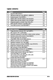
RAID controller selection (3-pin RAID_SEL1) 8. Hard disk activity... (10-1 pin USB34) 7. Serial port connector (10-1 pin COM2) 8. Backplane SMBus connector (6-1 pin BPSMB1) 12. Clear RTC RAM (CLRTC1) 2. USB device wake-up (3-pin USBPW12, USBPW34) 3. Serial ATA connectors (7-pin SATA1, SATA2, SATA3, SATA4) 4. Floppy...Reset button (Blue 2-pin RESET) Page 4-9 4-9 4-10 4-11 4-11 4-12 4-12 4-13 4-14 4-14 4-15 4-15 4-16 4-17 ASUS RS120-E3/PA4 4-3 Layout contents Jumpers 1. Printer port connector (26-1 pin LPT1) 10. Keyboard power (3-pin KBPWR1) 4. Force BIOS recovery (3-pin RECOVERY1)...
RAID controller selection (3-pin RAID_SEL1) 8. Hard disk activity... (10-1 pin USB34) 7. Serial port connector (10-1 pin COM2) 8. Backplane SMBus connector (6-1 pin BPSMB1) 12. Clear RTC RAM (CLRTC1) 2. USB device wake-up (3-pin USBPW12, USBPW34) 3. Serial ATA connectors (7-pin SATA1, SATA2, SATA3, SATA4) 4. Floppy...Reset button (Blue 2-pin RESET) Page 4-9 4-9 4-10 4-11 4-11 4-12 4-12 4-13 4-14 4-14 4-15 4-15 4-16 4-17 ASUS RS120-E3/PA4 4-3 Layout contents Jumpers 1. Printer port connector (26-1 pin LPT1) 10. Keyboard power (3-pin KBPWR1) 4. Force BIOS recovery (3-pin RECOVERY1)...
User Guide
Page 55
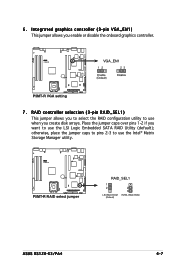
... (default); otherwise, place the jumper caps to pins 2-3 to use the Intel® Matrix Storage Manager utility. ® P5MT-R P5MT-R RAID select jumper RAID_SEL1 1 2 LSI RAID ROM (Default) 2 3 INTEL RAID ROM ASUS RS120-E3/PA4 4-7 6. Place the jumper caps over pins 1-2 if you create disk arrays. Integrated graphics controller (3-pin VGA_EN1) This jumper allows you enable...
... (default); otherwise, place the jumper caps to pins 2-3 to use the Intel® Matrix Storage Manager utility. ® P5MT-R P5MT-R RAID select jumper RAID_SEL1 1 2 LSI RAID ROM (Default) 2 3 INTEL RAID ROM ASUS RS120-E3/PA4 4-7 6. Place the jumper caps over pins 1-2 if you create disk arrays. Integrated graphics controller (3-pin VGA_EN1) This jumper allows you enable...
User Guide
Page 58
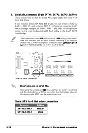
...SATA2, SATA3, SATA4) These connectors are set to I D E mode, you can create a RAID 0, RAID 1, RAID 10, and software RAID 5 configuration using the Intel® Matrix Storage Manager, or RAID 0, RAID 1, and RAID 10 configuration using these connectors. If you can connect Serial ATA boot/data hard disk drives to.... In I D E mode by default. Refer to the SATA1 or SATA2 connector. If you installed Serial ATA hard disk drives, you intend to create a Serial ATA RAID set the C o n f i g u r e S A T A A s item in I D E mode, connect the primary (boot) hard disk drive to the ...
...SATA2, SATA3, SATA4) These connectors are set to I D E mode, you can create a RAID 0, RAID 1, RAID 10, and software RAID 5 configuration using the Intel® Matrix Storage Manager, or RAID 0, RAID 1, and RAID 10 configuration using these connectors. If you can connect Serial ATA boot/data hard disk drives to.... In I D E mode by default. Refer to the SATA1 or SATA2 connector. If you installed Serial ATA hard disk drives, you intend to create a Serial ATA RAID set the C o n f i g u r e S A T A A s item in I D E mode, connect the primary (boot) hard disk drive to the ...
User Guide
Page 81
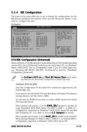
... Serial ATA hard disk drives as Parallel ATA physical storage devices, set the ATA/IDE Configuration to section 4.2 Jumpers for RAID 0, RAID 1, or RAID 0+1 configuration; If you are using legacy OS, e.g. supported on Windows® 2000/2003 Server/XP). Set to [...IDE operation mode depending on pins 1-2 of the R A I D _ S E L 1 jumper to create a RAID volume from Serial ATA hard disk drives. Select Screen Select Item +- ASUS RS120-E3/PA4 5-15 ATA/IDE Configuration [Enhanced] Allows selection of the RAID_SEL1 jumper to configure the item. (Defaults) Main BIOS ...
... Serial ATA hard disk drives as Parallel ATA physical storage devices, set the ATA/IDE Configuration to section 4.2 Jumpers for RAID 0, RAID 1, or RAID 0+1 configuration; If you are using legacy OS, e.g. supported on Windows® 2000/2003 Server/XP). Set to [...IDE operation mode depending on pins 1-2 of the R A I D _ S E L 1 jumper to create a RAID volume from Serial ATA hard disk drives. Select Screen Select Item +- ASUS RS120-E3/PA4 5-15 ATA/IDE Configuration [Enhanced] Allows selection of the RAID_SEL1 jumper to configure the item. (Defaults) Main BIOS ...
User Guide
Page 82
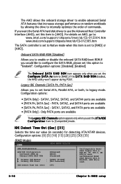
...- SATA1, SATA3, and PATA ports are available • [PATA Pri, SATA Sec] - WIN Me, 98, NT4.0, MS DOS)is set to [RAID] or [AHCI]. For details on random workloads by allowing the drive to internally optimize the order of commands. Win2000, WIN XP)is used . PATA, ...Chapter 5: BIOS setup If you set this option to configure the SATA RAID, please set the A T A/I D R O M disabled, the RAID utility won't appear during POST. Onboard SATA RAID ROM [Disabled] Allows you to enable or disable the onboard SATA RAID boot ROM.If you would like to "Enabeld". IDE Detect Time ...
...- SATA1, SATA3, and PATA ports are available • [PATA Pri, SATA Sec] - WIN Me, 98, NT4.0, MS DOS)is set to [RAID] or [AHCI]. For details on random workloads by allowing the drive to internally optimize the order of commands. Win2000, WIN XP)is used . PATA, ...Chapter 5: BIOS setup If you set this option to configure the SATA RAID, please set the A T A/I D R O M disabled, the RAID utility won't appear during POST. Onboard SATA RAID ROM [Disabled] Allows you to enable or disable the onboard SATA RAID boot ROM.If you would like to "Enabeld". IDE Detect Time ...
User Guide
Page 107
ASUS RS120-E3/PA4 RAID configuration Chapter 6 This chapter provides instructions for setting up, creating, and configuring RAID sets using the available utilities.
ASUS RS120-E3/PA4 RAID configuration Chapter 6 This chapter provides instructions for setting up, creating, and configuring RAID sets using the available utilities.
User Guide
Page 108
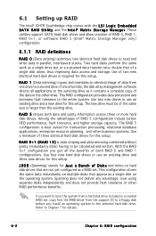
...parallel, interleaved stacks. The new drive must be calculated and written. R A I D 0 + 1 ( R A I D 5 stripes both RAID 0 and RAID 1 configurations. Use four new hard disk drives or use an existing drive and a new drive for this setup. Spanning does not deliver any advantage over... a single drive but at a sustained data transfer rate, double that of the same size or larger than the existing drive. Refer to the entire system. RAID 1 (Data mirroring) copies and maintains an identical image of three identical hard disk drives for J u s t a B u n c h o f D i s k s and refers to a ...
...parallel, interleaved stacks. The new drive must be calculated and written. R A I D 0 + 1 ( R A I D 5 stripes both RAID 0 and RAID 1 configurations. Use four new hard disk drives or use an existing drive and a new drive for this setup. Spanning does not deliver any advantage over... a single drive but at a sustained data transfer rate, double that of the same size or larger than the existing drive. Refer to the entire system. RAID 1 (Data mirroring) copies and maintains an identical image of three identical hard disk drives for J u s t a B u n c h o f D i s k s and refers to a ...
User Guide
Page 109
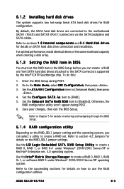
...Enhanced Mode], then press . 4. To do this: 1. Save your changes, then exit the BIOS Setup. ASUS RS120-E3/PA4 6-3 Refer to sections 1 . 5 I D S e t u p U t i l i t y to create a RAID 0, RAID 1, RAID 0+1, or software RAID 5 under Windows® 2000/2003 Server/XP or Red Hat® Enterprise ver. 3.0 operating system. ...Setup during POST. 6. Set the ATA/IDE Configuration item to [RAID]. 5. Set the O n b o a r d S A T A R A I n t e l® M a t r i x S t o r a g e M a n a g e r to create a RAID 0, RAID 1, or RAID 0+1 under Windows® 2000/2003 Server/XP operating system. ...
...Enhanced Mode], then press . 4. To do this: 1. Save your changes, then exit the BIOS Setup. ASUS RS120-E3/PA4 6-3 Refer to sections 1 . 5 I D S e t u p U t i l i t y to create a RAID 0, RAID 1, RAID 0+1, or software RAID 5 under Windows® 2000/2003 Server/XP or Red Hat® Enterprise ver. 3.0 operating system. ...Setup during POST. 6. Set the ATA/IDE Configuration item to [RAID]. 5. Set the O n b o a r d S A T A R A I n t e l® M a t r i x S t o r a g e M a n a g e r to create a RAID 0, RAID 1, or RAID 0+1 under Windows® 2000/2003 Server/XP operating system. ...
User Guide
Page 110
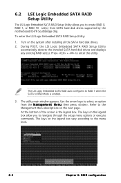
...n t M e n u, then press . At the bottom of the screen is enabled. 3. Turn on the legend box vary according to the menu level. 6-4 Chapter 6: RAID configuration Refer to create RAID 0, RAID 1, or RAID 10 set (s). The keys on the legend box allow you to the Management Menu descriptions on the next page. The LSI Logic Embedded... SATA RAID auto configures to RAID 1 when the SATA to navigate through the setup menu options or execute commands. Press + to select an option ...
...n t M e n u, then press . At the bottom of the screen is enabled. 3. Turn on the legend box vary according to the menu level. 6-4 Chapter 6: RAID configuration Refer to create RAID 0, RAID 1, or RAID 10 set (s). The keys on the legend box allow you to the Management Menu descriptions on the next page. The LSI Logic Embedded... SATA RAID auto configures to RAID 1 when the SATA to navigate through the setup menu options or execute commands. Press + to select an option ...
User Guide
Page 111
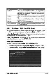
... menu, highlight C o n f i g u r e, then press . 2. Use the arrow keys to select Easy Configuration, then press . In E a s y C o n f i g u r a t i o n, the logical drive parameters are set using the E a s y C o n f i g u r a t i o n option: 1. ASUS RS120-E3/PA4 6-5 This menu also allows you to view, add, or clear RAID configurations or select the boot drive Allows you to initialize the logical drives of a created...
... menu, highlight C o n f i g u r e, then press . 2. Use the arrow keys to select Easy Configuration, then press . In E a s y C o n f i g u r a t i o n, the logical drive parameters are set using the E a s y C o n f i g u r a t i o n option: 1. ASUS RS120-E3/PA4 6-5 This menu also allows you to view, add, or clear RAID configurations or select the boot drive Allows you to initialize the logical drives of a created...
User Guide
Page 112
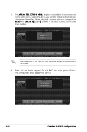
Select the drives you want to the SATA ports. Select all the drives required for the RAID set , then press . The configurable array appears on screen. 6-6 Chapter 6: RAID configuration The information of the selected hard disk drive displays at the bottom of the screen. 4. 3. The ARRAY SELECTION MENU displays the available drives connected to include in the RAID set , then press . When selected, the drive indicator changes from R E A D Y to ONLIN A[X]-[Y], where X is the array number, and Y is the drive number.
Select the drives you want to the SATA ports. Select all the drives required for the RAID set , then press . The configurable array appears on screen. 6-6 Chapter 6: RAID configuration The information of the selected hard disk drive displays at the bottom of the screen. 4. 3. The ARRAY SELECTION MENU displays the available drives connected to include in the RAID set , then press . When selected, the drive indicator changes from R E A D Y to ONLIN A[X]-[Y], where X is the array number, and Y is the drive number.
User Guide
Page 114
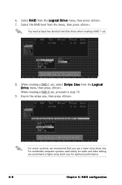
... and video editing, we recommend that you use a lower array block size. When creating a RAID 1 set, select S t r i p e S i z e from the L o g i c a l D r i v e menu, then press . 7. 6. Select R A I D from the L o g i c a l D r i v e menu, then press . Key-in the stripe size, then press . Select the RAID level from the menu, then press . For server systems, we recommend a higher array block...
... and video editing, we recommend that you use a lower array block size. When creating a RAID 1 set, select S t r i p e S i z e from the L o g i c a l D r i v e menu, then press . 7. 6. Select R A I D from the L o g i c a l D r i v e menu, then press . Key-in the stripe size, then press . Select the RAID level from the menu, then press . For server systems, we recommend a higher array block...
User Guide
Page 116
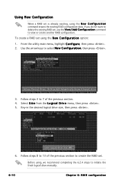
... drive size, then press . 6. Select S i z e from the L o g i c a l D r i v e menu, then press . 5. To create a RAID set , use the V i e w / A d d C o n f i g u r a t i o n command to delete the existing RAID set using the N e w C o n f i g u r a t i o n option: 1. Before using the N e w C o n f i g u r a t i o n command erases the existing RAID configuration data. Using New Configuration When a RAID set . Use the arrow keys to initiate the fresh logical drive manually. 6-10...
... drive size, then press . 6. Select S i z e from the L o g i c a l D r i v e menu, then press . 5. To create a RAID set , use the V i e w / A d d C o n f i g u r a t i o n command to delete the existing RAID set using the N e w C o n f i g u r a t i o n option: 1. Before using the N e w C o n f i g u r a t i o n command erases the existing RAID configuration data. Using New Configuration When a RAID set . Use the arrow keys to initiate the fresh logical drive manually. 6-10...
User Guide
Page 117
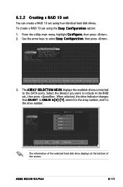
... disk drives. Select the drive(s) you want to select Easy Configuration, then press . 3. Use the arrow keys to include in the RAID set, then press . 6.2.2 Creating a RAID 10 set You can create a RAID 10 set using the E a s y C o n f i g u r a t i o n option: 1. When selected, the drive indicator changes from R E A D Y to the SATA ports. The ARRAY SELECTION MENU... drive number. The information of the selected hard disk drive displays at the bottom of the screen. From the utility main menu, highlight C o n f i g u r e, then press . 2. ASUS RS120-E3/PA4 6-11
... disk drives. Select the drive(s) you want to select Easy Configuration, then press . 3. Use the arrow keys to include in the RAID set, then press . 6.2.2 Creating a RAID 10 set You can create a RAID 10 set using the E a s y C o n f i g u r a t i o n option: 1. When selected, the drive indicator changes from R E A D Y to the SATA ports. The ARRAY SELECTION MENU... drive number. The information of the selected hard disk drive displays at the bottom of the screen. From the utility main menu, highlight C o n f i g u r e, then press . 2. ASUS RS120-E3/PA4 6-11
User Guide
Page 118
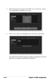
4. The logical drive information appears including a Logical Drive menu that allows you to change the logical drive parameters. 6-12 Chapter 6: RAID configuration The configurable array appears on screen. 5. Select all the drives required for the RAID 10 set, then press . Press , select the configurable array, then press .
4. The logical drive information appears including a Logical Drive menu that allows you to change the logical drive parameters. 6-12 Chapter 6: RAID configuration The configurable array appears on screen. 5. Select all the drives required for the RAID 10 set, then press . Press , select the configurable array, then press .