User Guide
Page 11
It includes sections on front panel and rear panel specifications. Product introduction Chapter 1 This chapter describes the general features of the chassis kit. ASUS RS120-E3/PA4 1-1
It includes sections on front panel and rear panel specifications. Product introduction Chapter 1 This chapter describes the general features of the chassis kit. ASUS RS120-E3/PA4 1-1

User Guide
Page 13
...the LGA775 package, and includes the latest technologies through the chipsets embedded on the motherboard. 1.2 System specifications The ASUS RS120-E3/PA4 is a 1U barebone server system featuring the ASUS P5MT-R motherboard. RAID 0, RAID 1, or RAID 10 configuration using the Intel® Matrix Storage Manager - ... Broadcom® BMC5721 Gigabit Ethernet Controller LAN2: Broadcom® BMC5721 Gigabit Ethernet Controller VGA ATI RAGE-XL PCI-based VGA controller with 8 MB display memory Expansion slots 1 x PCI Express x8 slot (PCI Express 1.0a) 1 x PCI-X 133 MHz/64-bit slot (PCI...
...the LGA775 package, and includes the latest technologies through the chipsets embedded on the motherboard. 1.2 System specifications The ASUS RS120-E3/PA4 is a 1U barebone server system featuring the ASUS P5MT-R motherboard. RAID 0, RAID 1, or RAID 10 configuration using the Intel® Matrix Storage Manager - ... Broadcom® BMC5721 Gigabit Ethernet Controller LAN2: Broadcom® BMC5721 Gigabit Ethernet Controller VGA ATI RAGE-XL PCI-based VGA controller with 8 MB display memory Expansion slots 1 x PCI Express x8 slot (PCI Express 1.0a) 1 x PCI-X 133 MHz/64-bit slot (PCI...
User Guide
Page 15
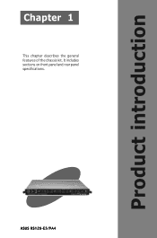
... (Port1) 10. Connect a USB floppy disk drive to any of the USB ports on the front or rear panel if you need to turn off) ASUS RS120-E3/PA4 1-5 Device fans (x 2) 6. Optical drive 1.6 • The barebone server does not include a floppy disk drive. Front I/O board (hidden) 13. 1.5 Internal features The barebone server includes the... LED Display status OFF ON Location LED Description Normal status Location switch is pressed (Press the location switch again to use a floppy disk. • Only ASUS CD/DVD-ROMs fit the optical drive bay. SATA backplane 8.
... (Port1) 10. Connect a USB floppy disk drive to any of the USB ports on the front or rear panel if you need to turn off) ASUS RS120-E3/PA4 1-5 Device fans (x 2) 6. Optical drive 1.6 • The barebone server does not include a floppy disk drive. Front I/O board (hidden) 13. 1.5 Internal features The barebone server includes the... LED Display status OFF ON Location LED Description Normal status Location switch is pressed (Press the location switch again to use a floppy disk. • Only ASUS CD/DVD-ROMs fit the optical drive bay. SATA backplane 8.
User Guide
Page 17
Chapter 2 This chapter lists the hardware setup procedures that you have to perform when installing or removing system components. Hardware setup ASUS RS120-E3/PA4 2-1
Chapter 2 This chapter lists the hardware setup procedures that you have to perform when installing or removing system components. Hardware setup ASUS RS120-E3/PA4 2-1
User Guide
Page 19
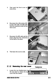
Thumbscrews ASUS RS120-E3/PA4 2-3 Loosen the two thumbscrews on the rear panel to release the top cover from the connectors on the back of the drive. 8. Then leave the cover as arrow show. 6. 5. Disconnect the IDE cable and the power plug from the chassis. Then push the front cover as side. 2.1.2 Removing the rear cover 1. Disconnect the LAN activity LED/ Locator LED cable and USB cable from the connectors under the top front cover. 7.
Thumbscrews ASUS RS120-E3/PA4 2-3 Loosen the two thumbscrews on the rear panel to release the top cover from the connectors on the back of the drive. 8. Then leave the cover as arrow show. 6. 5. Disconnect the IDE cable and the power plug from the chassis. Then push the front cover as side. 2.1.2 Removing the rear cover 1. Disconnect the LAN activity LED/ Locator LED cable and USB cable from the connectors under the top front cover. 7.
User Guide
Page 21
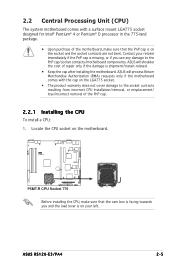
... shoulder the cost of repair only if the damage is shipment/transit-related. • Keep the cap after installing the motherboard. ASUS RS120-E3/PA4 2-5 ASUS will process Return Merchandise Authorization (RMA) requests only if the motherboard comes with a surface mount LGA775 socket designed for Intel® Pentium® 4 or Pentium&#...
... shoulder the cost of repair only if the damage is shipment/transit-related. • Keep the cap after installing the motherboard. ASUS RS120-E3/PA4 2-5 ASUS will process Return Merchandise Authorization (RMA) requests only if the motherboard comes with a surface mount LGA775 socket designed for Intel® Pentium® 4 or Pentium&#...
User Guide
Page 23
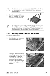
... heatsink and airduct To install the CPU heatsink: 1. Twist each of the installed CPU. 2. Carefully place the heatsink on the socket and damaging the CPU! ASUS RS120-E3/PA4 2-7 DO NOT force the CPU into the retention tab. A 6. Refer to the motherboard.
... heatsink and airduct To install the CPU heatsink: 1. Twist each of the installed CPU. 2. Carefully place the heatsink on the socket and damaging the CPU! ASUS RS120-E3/PA4 2-7 DO NOT force the CPU into the retention tab. A 6. Refer to the motherboard.
User Guide
Page 25
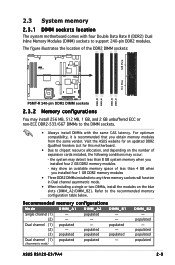
... vendor. Recommended memory configurations Mode DIMM_A1 DIMM_A2 DIMM_B1 Single channel (1) - populated - (2) - - - may install 256 MB, 512 MB, 1 GB, and 2 GB unbuffered ECC or non-ECC DDR2-533/667 DIMMs to the DIMM sockets. • ...Dual channel (1) populated (2) - - Refer to chipset resource allocation, and depending on the blue slots (DIMM_A2/DIMM_B2). populated populated populated ASUS RS120-E3/PA4 2-9 populated populated - (3) populated populated populated Dual channel (1) populated populated - (Asymmetric mode) DIMM_B2 - 2.3 System memory 2.3.1 DIMM...
... vendor. Recommended memory configurations Mode DIMM_A1 DIMM_A2 DIMM_B1 Single channel (1) - populated - (2) - - - may install 256 MB, 512 MB, 1 GB, and 2 GB unbuffered ECC or non-ECC DDR2-533/667 DIMMs to the DIMM sockets. • ...Dual channel (1) populated (2) - - Refer to chipset resource allocation, and depending on the blue slots (DIMM_A2/DIMM_B2). populated populated populated ASUS RS120-E3/PA4 2-9 populated populated - (3) populated populated populated Dual channel (1) populated populated - (Asymmetric mode) DIMM_B2 - 2.3 System memory 2.3.1 DIMM...
User Guide
Page 27
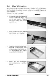
... the drive tray out of the drive tray holes. Place a SATA hard disk drive on the left tray connects to secure the hard disk drive. 4. ASUS RS120-E3/PA4 2-11 Use two screws on each side to the motherboard SATA ports via SATA backplane. The drive tray ejects slightly after you pull out the...
... the drive tray out of the drive tray holes. Place a SATA hard disk drive on the left tray connects to secure the hard disk drive. 4. ASUS RS120-E3/PA4 2-11 Use two screws on each side to the motherboard SATA ports via SATA backplane. The drive tray ejects slightly after you pull out the...
User Guide
Page 29
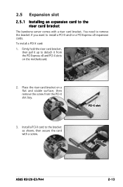
... Express x8 and PCI-X slots on a flat and stable surface, then remove the screw from the PCI-X slot bay. 3. To install a PCI-X card: 1. PCI-X slot ASUS RS120-E3/PA4 2-13
... Express x8 and PCI-X slots on a flat and stable surface, then remove the screw from the PCI-X slot bay. 3. To install a PCI-X card: 1. PCI-X slot ASUS RS120-E3/PA4 2-13
User Guide
Page 31
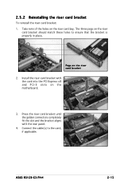
... Express x8 and PCI-X slots on the riser card bracket 2. 2.5.2 Reinstalling the riser card bracket To reinstall the riser card bracket: 1. Pegs on the motherboard. 3. ASUS RS120-E3/PA4 2-15 The three pegs on the riser card bay. Take note of the holes on the riser card bracket should match these holes to the...
... Express x8 and PCI-X slots on the riser card bracket 2. 2.5.2 Reinstalling the riser card bracket To reinstall the riser card bracket: 1. Pegs on the motherboard. 3. ASUS RS120-E3/PA4 2-15 The three pegs on the riser card bay. Take note of the holes on the riser card bracket should match these holes to the...
User Guide
Page 33
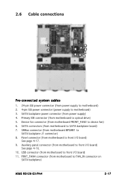
Device fan connector (from motherboard to FAN_IN connector on SATA backplane) ASUS RS120-E3/PA4 2-17 FRNT_FAN4 connector (from motherboard FRONT_FAN3 to device fan) 6. USB connector (from motherboard to front I/O board) See page 4-17. 9. Panel connector (from motherboard to front I /O ...
Device fan connector (from motherboard to FAN_IN connector on SATA backplane) ASUS RS120-E3/PA4 2-17 FRNT_FAN4 connector (from motherboard FRONT_FAN3 to device fan) 6. USB connector (from motherboard to front I/O board) See page 4-17. 9. Panel connector (from motherboard to front I /O ...
User Guide
Page 35
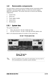
... remove previously installed system components when installing or removing system devices, or when you need to CPU overheating and/or automatic system shutdown. System fans 2. ASUS RS120-E3/PA4 2-19 Power supply module 4. This section tells how to remove the following components: 1.
... remove previously installed system components when installing or removing system devices, or when you need to CPU overheating and/or automatic system shutdown. System fans 2. ASUS RS120-E3/PA4 2-19 Power supply module 4. This section tells how to remove the following components: 1.
User Guide
Page 37
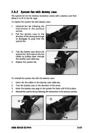
... case cable bay. 2. Turn the dummy case above the system fan, then remove the fan cables by following the instructions in the previous section. 3 1 2 Peg ASUS RS120-E3/PA4 2-21 Peg 3. 2.8.2 System fan with dummy case The system fan for the memory module(s) comes with a dummy case that allows it fits in the fan...
... case cable bay. 2. Turn the dummy case above the system fan, then remove the fan cables by following the instructions in the previous section. 3 1 2 Peg ASUS RS120-E3/PA4 2-21 Peg 3. 2.8.2 System fan with dummy case The system fan for the memory module(s) comes with a dummy case that allows it fits in the fan...

User Guide
Page 39
Slide the power supply forward for about half an inch, then carefully lift it out from the chassis. 4. Use a Phillips (cross) screwdriver to the motherboard and other system devices. 2. From the rear panel, remove two screws that secure the front end of the power supply. 3. ASUS RS120-E3/PA4 2-23 2.8.4 Power supply module To uninstall the power supply module: 1. Disconnect all the power cables connected to remove the screws that secure the power supply from the chassis.
Slide the power supply forward for about half an inch, then carefully lift it out from the chassis. 4. Use a Phillips (cross) screwdriver to the motherboard and other system devices. 2. From the rear panel, remove two screws that secure the front end of the power supply. 3. ASUS RS120-E3/PA4 2-23 2.8.4 Power supply module To uninstall the power supply module: 1. Disconnect all the power cables connected to remove the screws that secure the power supply from the chassis.
User Guide
Page 41
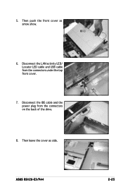
Disconnect the IDE cable and the power plug from the connectors under the top front cover. 7. Then leave the cover as arrow show. 6. 5. ASUS RS120-E3/PA4 2-25 Then push the front cover as side. Disconnect the LAN activity LED/ Locator LED cable and USB cable from the connectors on the back of the drive. 8.
Disconnect the IDE cable and the power plug from the connectors under the top front cover. 7. Then leave the cover as arrow show. 6. 5. ASUS RS120-E3/PA4 2-25 Then push the front cover as side. Disconnect the LAN activity LED/ Locator LED cable and USB cable from the connectors on the back of the drive. 8.
User Guide
Page 43
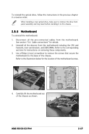
.... See section "2.6 Cable connections" for instructions on removing these components. 3. Refer to the corresponding sections for details. 2. Carefully lift the motherboard out of the chassis. ASUS RS120-E3/PA4 2-27 When installing a new optical drive, make sure to remove the drive front panel assembly and tray bezel before installing it to the base of...
.... See section "2.6 Cable connections" for instructions on removing these components. 3. Refer to the corresponding sections for details. 2. Carefully lift the motherboard out of the chassis. ASUS RS120-E3/PA4 2-27 When installing a new optical drive, make sure to remove the drive front panel assembly and tray bezel before installing it to the base of...

User Guide
Page 45
Installation options Chapter 3 This chapter describes how to install the optional components and devices into the barebone server. ASUS RS120-E3/PA4 2-1
Installation options Chapter 3 This chapter describes how to install the optional components and devices into the barebone server. ASUS RS120-E3/PA4 2-1
User Guide
Page 47
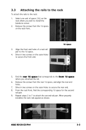
... 5. When properly installed, the rack rails appear as shown. Align the front end holes of space (1U) on the outer holes to the 1U space. 4. ASUS RS120-E3/PA4 3-3 From the rack front, find the corresponding 1U space for the second rail pair. 9. Remove the screws from the rear 1U space, and align the...
... 5. When properly installed, the rack rails appear as shown. Align the front end holes of space (1U) on the outer holes to the 1U space. 4. ASUS RS120-E3/PA4 3-3 From the rack front, find the corresponding 1U space for the second rail pair. 9. Remove the screws from the rear 1U space, and align the...
User Guide
Page 49
ASUS RS120-E3/PA4 Motherboard info Chapter 4 This chapter includes the motherboard layout, and brief descriptions of the jumpers and internal connectors.
ASUS RS120-E3/PA4 Motherboard info Chapter 4 This chapter includes the motherboard layout, and brief descriptions of the jumpers and internal connectors.