
User Guide
Page 3
... the front cover 2-2 2.1.2 Removing the rear cover 2-2 2.1.3 Installing the cover 2-3 2.2 Central Processing Unit (CPU 2-4 2.2.1 Installing the CPU 2-4 2.2.2 Installing the CPU heatsink and airduct 2-6 2.3 System memory 2-8 2.3.1 DIMM sockets location 2-8 2.3.2 Memory configurations 2-8 2.3.3 Installing a DIMM 2-9 2.3.4 Removing a DIMM 2-9 2.4 Hard disk drives 2-10 2.5 Expansion slot 2-12 2.5.1 Installing an expansion card to the riser card bracket 2-12 2.5.2 Reinstalling...
... the front cover 2-2 2.1.2 Removing the rear cover 2-2 2.1.3 Installing the cover 2-3 2.2 Central Processing Unit (CPU 2-4 2.2.1 Installing the CPU 2-4 2.2.2 Installing the CPU heatsink and airduct 2-6 2.3 System memory 2-8 2.3.1 DIMM sockets location 2-8 2.3.2 Memory configurations 2-8 2.3.3 Installing a DIMM 2-9 2.3.4 Removing a DIMM 2-9 2.4 Hard disk drives 2-10 2.5 Expansion slot 2-12 2.5.1 Installing an expansion card to the riser card bracket 2-12 2.5.2 Reinstalling...

User Guide
Page 13
...-ECC DIMMs Supports dual-channel memory architecture LAN LAN1: Broadcom® BMC5721 Gigabit Ethernet Controller LAN2: Broadcom® BMC5721 Gigabit Ethernet Controller VGA ATI RAGE-XL PCI-based VGA controller with - ASUS RS120-E3/PA4 1-3 RAID 0, RAID ...MB display memory Expansion slots 1 x PCI Express x8 slot (PCI Express 1.0a) 1 x PCI-X 133 MHz/64-bit slot (PCI-X 1.0) 1 x PCI 33 MHz/32-bit/5V slot (PCI 2.3)* 1 x mini-PCI socket for debug card. RAID 0, RAID 1, or RAID 10 configuration using the Intel® Matrix Storage Manager - 1.2 System specifications The ASUS RS120-E3...
...-ECC DIMMs Supports dual-channel memory architecture LAN LAN1: Broadcom® BMC5721 Gigabit Ethernet Controller LAN2: Broadcom® BMC5721 Gigabit Ethernet Controller VGA ATI RAGE-XL PCI-based VGA controller with - ASUS RS120-E3/PA4 1-3 RAID 0, RAID ...MB display memory Expansion slots 1 x PCI Express x8 slot (PCI Express 1.0a) 1 x PCI-X 133 MHz/64-bit slot (PCI-X 1.0) 1 x PCI 33 MHz/32-bit/5V slot (PCI 2.3)* 1 x mini-PCI socket for debug card. RAID 0, RAID 1, or RAID 10 configuration using the Intel® Matrix Storage Manager - 1.2 System specifications The ASUS RS120-E3...
User Guide
Page 23
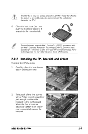
... and damaging the CPU! Carefully place the heatsink on top of the four screws with the Intel® Enhanced Memory 64 Technology (EM64T), Enhanced Intel SpeedStep® Technology (EIST), and Hyper-Threading Technology. ASUS RS120-E3/PA4 2-7 B The motherboard supports Intel® Pentium® 4 LGA775 processors with a Philips (cross) screwdriver just enough to attach...
... and damaging the CPU! Carefully place the heatsink on top of the four screws with the Intel® Enhanced Memory 64 Technology (EM64T), Enhanced Intel SpeedStep® Technology (EIST), and Hyper-Threading Technology. ASUS RS120-E3/PA4 2-7 B The motherboard supports Intel® Pentium® 4 LGA775 processors with a Philips (cross) screwdriver just enough to attach...
User Guide
Page 25
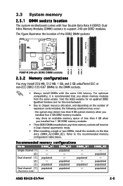
..., it is recommended that you obtain memory modules from the same vendor. populated populated - (3) populated populated populated Dual channel (1) populated populated - (Asymmetric mode) DIMM_B2 - populated - (2) - - - populated populated populated ASUS RS120-E3/PA4 2-9 Visit the ASUS website for an updated DDR2 Qualified Vendors...into any three memory sockets will function in Dual channel asymmetric mode. • When installing a single or two DIMMs, install the modules on the number of expansion cards installed, the following conditions may install 256 MB, 512 MB, 1 GB,...
..., it is recommended that you obtain memory modules from the same vendor. populated populated - (3) populated populated populated Dual channel (1) populated populated - (Asymmetric mode) DIMM_B2 - populated - (2) - - - populated populated populated ASUS RS120-E3/PA4 2-9 Visit the ASUS website for an updated DDR2 Qualified Vendors...into any three memory sockets will function in Dual channel asymmetric mode. • When installing a single or two DIMMs, install the modules on the number of expansion cards installed, the following conditions may install 256 MB, 512 MB, 1 GB,...
User Guide
Page 37
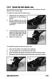
Uninstall the fan following the instructions in the previous section. 3 1 2 Peg ASUS RS120-E3/PA4 2-21 Peg 3. Turn the dummy case above the system fan, then remove the fan cables by following the instructions in the previous section. 2. To ... the dummy case cable bay. 2. Insert the fan cables to fit in the fan cage. 2.8.2 System fan with dummy case The system fan for the memory module(s) comes with a dummy case that allows it fits in place. 4.
Uninstall the fan following the instructions in the previous section. 3 1 2 Peg ASUS RS120-E3/PA4 2-21 Peg 3. Turn the dummy case above the system fan, then remove the fan cables by following the instructions in the previous section. 2. To ... the dummy case cable bay. 2. Insert the fan cables to fit in the fan cage. 2.8.2 System fan with dummy case The system fan for the memory module(s) comes with a dummy case that allows it fits in place. 4.
User Guide
Page 52
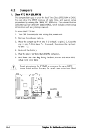
... you to pins 1-2. 4. The onboard button cell battery powers the RAM data in CMOS. Keep the cap on CLRTC jumper default position. Plug the power cord and turn ON the computer. 6. 4.2 Jumpers 1. You can clear the CMOS memory of date, time, and system setup parameters by erasing the CMOS ...RTC RAM data. Hold down the key during the boot process and enter BIOS setup to pins 2-3. Except when clearing the...
... you to pins 1-2. 4. The onboard button cell battery powers the RAM data in CMOS. Keep the cap on CLRTC jumper default position. Plug the power cord and turn ON the computer. 6. 4.2 Jumpers 1. You can clear the CMOS memory of date, time, and system setup parameters by erasing the CMOS ...RTC RAM data. Hold down the key during the boot process and enter BIOS setup to pins 2-3. Except when clearing the...
User Guide
Page 84
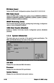
... Date : 12/22/05 BIOS SETUP UTILITY Processor Type Speed Count : Genuine Intel(R) CPU 3.20GHz : 3200 MHz : 1 System Memory Total : 1024MB Select Screen Select Item +- The BIOS automatically detects the items in this menu. Configuration options: [Disabled] [Enabled] ...] 32Bit Data Transfer [Disabled] Enables or disables 32-bit data transfer. AMI BIOS Displays the auto-detected BIOS information. System Memory Displays the auto-detected total system memory. 5-18 Chapter 5: BIOS setup Configuration options: [Auto] [0] [1] [2] [3] [4] DMA Mode [Auto] Selects the DMA ...
... Date : 12/22/05 BIOS SETUP UTILITY Processor Type Speed Count : Genuine Intel(R) CPU 3.20GHz : 3200 MHz : 1 System Memory Total : 1024MB Select Screen Select Item +- The BIOS automatically detects the items in this menu. Configuration options: [Disabled] [Enabled] ...] 32Bit Data Transfer [Disabled] Enables or disables 32-bit data transfer. AMI BIOS Displays the auto-detected BIOS information. System Memory Displays the auto-detected total system memory. 5-18 Chapter 5: BIOS setup Configuration options: [Auto] [0] [1] [2] [3] [4] DMA Mode [Auto] Selects the DMA ...
User Guide
Page 86
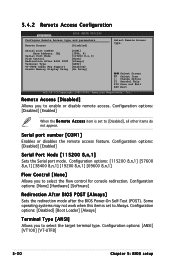
... Access [Disabled] Serial port number Base Address, IRQ Serial Port Mode Flow Control Redirection After BIOS POST Terminal Type VT-UTFB Combo Key Support Sredir Memory Display Delay [COM1] [3F8h, 4] [115200 8,n,1] [None] [Always] [ANSI] [Enabled] [No Delay] Select Remote Access type. Select Screen Select Item +- Serial port number [COM1] Enables or...
... Access [Disabled] Serial port number Base Address, IRQ Serial Port Mode Flow Control Redirection After BIOS POST Terminal Type VT-UTFB Combo Key Support Sredir Memory Display Delay [COM1] [3F8h, 4] [115200 8,n,1] [None] [Always] [ANSI] [Enabled] [No Delay] Select Remote Access type. Select Screen Select Item +- Serial port number [COM1] Enables or...
User Guide
Page 87
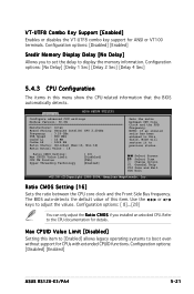
Configuration options: [Disabled] [Enabled] Sredir Memory Display Delay [No Delay] Allows you installed an unlocked CPU. Ratio CMOS Setting [16] Sets the ratio between CPU Core Clock and the FSB Frequency. ... operating systems to display the memory information. Refer to previous status. Select Screen Select Item +- Change Option F1 General Help F10 Save and Exit ESC Exit v02.58 (C)Copyright 1985-2004, American Megatrends, Inc. Use the < + > or < - > keys to adjust the values. Configuration options: [Disabled] [Enabled] ASUS RS120-E3/PA4 5-21 Advanced BIOS SETUP...
Configuration options: [Disabled] [Enabled] Sredir Memory Display Delay [No Delay] Allows you installed an unlocked CPU. Ratio CMOS Setting [16] Sets the ratio between CPU Core Clock and the FSB Frequency. ... operating systems to display the memory information. Refer to previous status. Select Screen Select Item +- Change Option F1 General Help F10 Save and Exit ESC Exit v02.58 (C)Copyright 1985-2004, American Megatrends, Inc. Use the < + > or < - > keys to adjust the values. Configuration options: [Disabled] [Enabled] ASUS RS120-E3/PA4 5-21 Advanced BIOS SETUP...

User Guide
Page 89
... to change the advanced chipset settings. Select Screen Select Item +- Configuration options: [Disabled] [Enabled] ASUS RS120-E3/PA4 5-23 Change Option F1 General Help F10 Save and Exit ESC Exit v02.58 (C)Copyright 1985-2004, American Megatrends, Inc. Memory Remap Feature [Enabled] Allows you to display the sub-menu. Onboard LAN Boot ROM [Enabled...
... to change the advanced chipset settings. Select Screen Select Item +- Configuration options: [Disabled] [Enabled] ASUS RS120-E3/PA4 5-23 Change Option F1 General Help F10 Save and Exit ESC Exit v02.58 (C)Copyright 1985-2004, American Megatrends, Inc. Memory Remap Feature [Enabled] Allows you to display the sub-menu. Onboard LAN Boot ROM [Enabled...

User Guide
Page 94
...] When set to malfunction! The menu includes setting the IRQ and DMA channel resources for either PCI/PnP or legacy ISA devices, and setting the memory size block for boot if your system has a Plug ans Play operating system. Configuration options: [Yes] [No] Palette Snooping [Disabled] When set to [No], BIOS...
...] When set to malfunction! The menu includes setting the IRQ and DMA channel resources for either PCI/PnP or legacy ISA devices, and setting the memory size block for boot if your system has a Plug ans Play operating system. Configuration options: [Yes] [No] Palette Snooping [Disabled] When set to [No], BIOS...

