Users Manual English
Page 15
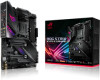
... you install or remove any component, ensure that the ATX power supply is switched off or the power cord is detached from the power supply. ASUS ROG STRIX X570-E GAMING 1-1
... you install or remove any component, ensure that the ATX power supply is switched off or the power cord is detached from the power supply. ASUS ROG STRIX X570-E GAMING 1-1
Users Manual English
Page 17
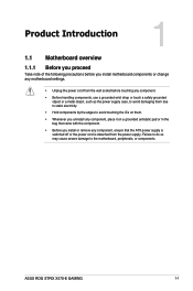
... PCH_FAN) 24. BIOS Flashback button (BIOS_FLBK) Page 1-19 1-18 1-21 1-4 1-11 1-4 1-8 1-12 1-15 1-20 1-10 1-14 1-17 1-15 1-16 1-13 1-21 1-8 1-13 1-6 1-6 1-9 1-22 1-16 1-9 2-13 ASUS ROG STRIX X570-E GAMING 1-3 Addressable RGB header (4-1 pin ADD_GEN2_1/2) 9. Chapter 1 Layout contents Connectors/Jumpers/Buttons and switches/Slots 1. ATX power connectors (24-pin EATXPWR; 8-pin EATX12V) 2. Clear RTC RAM...
... PCH_FAN) 24. BIOS Flashback button (BIOS_FLBK) Page 1-19 1-18 1-21 1-4 1-11 1-4 1-8 1-12 1-15 1-20 1-10 1-14 1-17 1-15 1-16 1-13 1-21 1-8 1-13 1-6 1-6 1-9 1-22 1-16 1-9 2-13 ASUS ROG STRIX X570-E GAMING 1-3 Addressable RGB header (4-1 pin ADD_GEN2_1/2) 9. Chapter 1 Layout contents Connectors/Jumpers/Buttons and switches/Slots 1. ATX power connectors (24-pin EATXPWR; 8-pin EATX12V) 2. Clear RTC RAM...

Users Manual English
Page 19
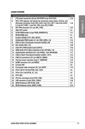
... operation frequency is dependent on its Serial Presence Detect (SPD), which is the standard way of the same version or data code (D/C) from a memory module. ASUS ROG STRIX X570-E GAMING 1-5 Under the default state, some memory modules for the dual-channel configuration.
... operation frequency is dependent on its Serial Presence Detect (SPD), which is the standard way of the same version or data code (D/C) from a memory module. ASUS ROG STRIX X570-E GAMING 1-5 Under the default state, some memory modules for the dual-channel configuration.
Users Manual English
Page 21
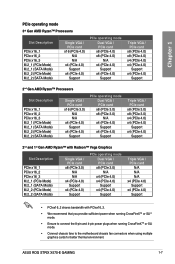
... when running CrossFireXTM or SLI mode. • Connect chassis fans to the motherboard chassis fan connectors when using multiple graphics cards for better thermal environment. ASUS ROG STRIX X570-E GAMING 1-7
... when running CrossFireXTM or SLI mode. • Connect chassis fans to the motherboard chassis fan connectors when using multiple graphics cards for better thermal environment. ASUS ROG STRIX X570-E GAMING 1-7
Users Manual English
Page 23
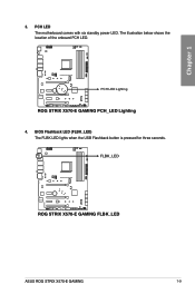
BIOS Flashback LED (FLBK_LED) The FLBK LED lights when the USB Flashback button is pressed for three seconds. FLBK_LED STRIX X570-e GAMING ROG STRIX X570-E GAMING FLBK_LED ASUS ROG STRIX X570-E GAMING 1-9 Chapter 1 3. STRIX X570-e GAMING PCH LED Lighting ROG STRIX X570-E GAMING PCH_LED Lighting 4. PCH LED The motherboard comes with six standby power LED. The illustration below shows the location of the onboard PCH LED.
BIOS Flashback LED (FLBK_LED) The FLBK LED lights when the USB Flashback button is pressed for three seconds. FLBK_LED STRIX X570-e GAMING ROG STRIX X570-E GAMING FLBK_LED ASUS ROG STRIX X570-E GAMING 1-9 Chapter 1 3. STRIX X570-e GAMING PCH LED Lighting ROG STRIX X570-E GAMING PCH_LED Lighting 4. PCH LED The motherboard comes with six standby power LED. The illustration below shows the location of the onboard PCH LED.
Users Manual English
Page 25
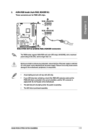
... you install or remove any component, ensure that the ATX power supply is switched off or the power cord is purchased separately. ASUS ROG STRIX X570-E GAMING 1-11 STRIX X570-e GAMING A RGB_HEADER1 A PIN 1 +12V G R B B RGB_HEADER2 PIN 1 +12V G R B B ROG STRIX X570-E GAMING RGB_HEADER connectors The RGB header supports 5050 RGB multi-color LED strips (12V/G/R/B), with the 12V header on the motherboard. •...
... you install or remove any component, ensure that the ATX power supply is switched off or the power cord is purchased separately. ASUS ROG STRIX X570-E GAMING 1-11 STRIX X570-e GAMING A RGB_HEADER1 A PIN 1 +12V G R B B RGB_HEADER2 PIN 1 +12V G R B B ROG STRIX X570-E GAMING RGB_HEADER connectors The RGB header supports 5050 RGB multi-color LED strips (12V/G/R/B), with the 12V header on the motherboard. •...

Users Manual English
Page 27
...panel audio I /O module cable to this connector to this connector. AGND NC SENSE1_RETUR SENSE2_RETUR STRIX X570-e GAMING AAFP PORT1 L PORT1 R PORT2 R SENSE_SEND PORT2 L HD-audio-compliant pin definition ROG STRIX X570-E GAMING Analog front panel connector We recommend that monitors the temperature of the motherboard's high-definition audio.... Chapter 1 4. Connect one end of the front panel audio I /O module that supports HD Audio. ASUS ROG STRIX X570-E GAMING 1-13 STRIX X570-e GAMING T_SENSOR GND PIN 1 SENSOR IN ROG STRIX X570-E GAMING T_SENSOR connector 1.1.8 Internal connectors 1.
...panel audio I /O module cable to this connector to this connector. AGND NC SENSE1_RETUR SENSE2_RETUR STRIX X570-e GAMING AAFP PORT1 L PORT1 R PORT2 R SENSE_SEND PORT2 L HD-audio-compliant pin definition ROG STRIX X570-E GAMING Analog front panel connector We recommend that monitors the temperature of the motherboard's high-definition audio.... Chapter 1 4. Connect one end of the front panel audio I /O module that supports HD Audio. ASUS ROG STRIX X570-E GAMING 1-13 STRIX X570-e GAMING T_SENSOR GND PIN 1 SENSOR IN ROG STRIX X570-E GAMING T_SENSOR connector 1.1.8 Internal connectors 1.

Users Manual English
Page 29
.../s, faster charging time for additional USB 3.2 Gen1 front or rear panel ports. The next-generation standard is purchased separately. 4. ASUS ROG STRIX X570-E GAMING 1-15 USB 3.2 Gen2 front panel connector (U32G2_C9) This connector allows you can enjoy all the benefits of USB 3.2 Gen1 ...including faster data transfer speeds of up to 10 Gbps. GND IntA_P1_SSRX+ IntA_P1_SSRX- Vbus ROG STRIX X570-E GAMING USB 3.2 Gen1 connectors The USB 3.2 Gen1 module is purchased separately. With an installed USB 3.2 Gen1 module, you to connect...
.../s, faster charging time for additional USB 3.2 Gen1 front or rear panel ports. The next-generation standard is purchased separately. 4. ASUS ROG STRIX X570-E GAMING 1-15 USB 3.2 Gen2 front panel connector (U32G2_C9) This connector allows you can enjoy all the benefits of USB 3.2 Gen1 ...including faster data transfer speeds of up to 10 Gbps. GND IntA_P1_SSRX+ IntA_P1_SSRX- Vbus ROG STRIX X570-E GAMING USB 3.2 Gen1 connectors The USB 3.2 Gen1 module is purchased separately. With an installed USB 3.2 Gen1 module, you to connect...

Users Manual English
Page 31
... system beeps and warnings. • ATX power button/soft-off the system power. STRIX X570-e GAMING ROG STRIX X570-E GAMING SPEAKER & F_PANEL connectors • System power LED (2-pin PLED) This 2-pin connector is for the chassis-mounted reset button for the system power LED. ASUS ROG STRIX X570-E GAMING 1-17 Pressing the power button for more than four seconds while the system...
... system beeps and warnings. • ATX power button/soft-off the system power. STRIX X570-e GAMING ROG STRIX X570-E GAMING SPEAKER & F_PANEL connectors • System power LED (2-pin PLED) This 2-pin connector is for the chassis-mounted reset button for the system power LED. ASUS ROG STRIX X570-E GAMING 1-17 Pressing the power button for more than four seconds while the system...

Users Manual English
Page 33
...EATX12V_1; 4-pin EATX12V_2) These connectors are designed to fit these connectors in only one orientation. ASUS ROG STRIX X570-E GAMING 1-19 Find the proper orientation and push down firmly until the connectors completely fit. STRIX X570-e GAMING A A B EATX_12V_2 EATX_12V_1 EATXPWR +DC_IN +DC_IN +12V DC +12V DC +12V DC... GND GND GND GND GND GND GND GND +5 Volts PSON# GND GND +3 Volts -12 Volts +3 Volts +3 Volts PIN 1 ROG STRIX X570-E GAMING power connectors • DO NOT connect the 4-pin power plug only, the motherboard may not boot up if the power is inadequate....
...EATX12V_1; 4-pin EATX12V_2) These connectors are designed to fit these connectors in only one orientation. ASUS ROG STRIX X570-E GAMING 1-19 Find the proper orientation and push down firmly until the connectors completely fit. STRIX X570-e GAMING A A B EATX_12V_2 EATX_12V_1 EATXPWR +DC_IN +DC_IN +12V DC +12V DC +12V DC... GND GND GND GND GND GND GND GND +5 Volts PSON# GND GND +3 Volts -12 Volts +3 Volts +3 Volts PIN 1 ROG STRIX X570-E GAMING power connectors • DO NOT connect the 4-pin power plug only, the motherboard may not boot up if the power is inadequate....
Users Manual English
Page 35
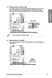
... +1.8V TPM PLTRST# +18V SPI SPI CS# SPI MISO SPI HOLD# SPI TPM IRQ# SPI TPM CS# SPI FLASH WP# GND SPI CLK SPI MOSI ROG STRIX X570-E GAMING SPI TPM connector The SPI TPM module is purchased separately. 12. SPI TPM connector (14-1 pin SPI_TPM) This connector supports a Trusted Platform Module (TPM) system... identities, and ensures platform integrity. NODE connector (12-1 pin NODE) This connector allows you to connect a compatible PSU or control a compatible fan extension card. STRIX X570-e GAMING ROG STRIX X570-E GAMING Node connector ASUS ROG STRIX X570-E GAMING 1-21 Chapter 1 11.
... +1.8V TPM PLTRST# +18V SPI SPI CS# SPI MISO SPI HOLD# SPI TPM IRQ# SPI TPM CS# SPI FLASH WP# GND SPI CLK SPI MOSI ROG STRIX X570-E GAMING SPI TPM connector The SPI TPM module is purchased separately. 12. SPI TPM connector (14-1 pin SPI_TPM) This connector supports a Trusted Platform Module (TPM) system... identities, and ensures platform integrity. NODE connector (12-1 pin NODE) This connector allows you to connect a compatible PSU or control a compatible fan extension card. STRIX X570-e GAMING ROG STRIX X570-E GAMING Node connector ASUS ROG STRIX X570-E GAMING 1-21 Chapter 1 11.
Users Manual English
Page 37
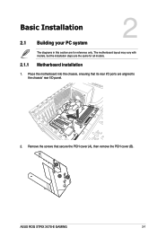
Chapter 2: Basic Installation Basic Installation 2.1 Building your PC system 2 2.1.1 The diagrams in this section are for all models. Place the motherboard into the chassis, ensuring that secure the PCH cover (A), then remove the PCH cover (B). Motherboard installation 1. The motherboard layout may vary with models, but the installation steps are aligned to the chassis' rear I /O ports are the same for reference only. Chapter 2 ASUS ROG STRIX X570-E GAMING 2-1 Remove the screws that its rear I /O panel. 2.
Chapter 2: Basic Installation Basic Installation 2.1 Building your PC system 2 2.1.1 The diagrams in this section are for all models. Place the motherboard into the chassis, ensuring that secure the PCH cover (A), then remove the PCH cover (B). Motherboard installation 1. The motherboard layout may vary with models, but the installation steps are aligned to the chassis' rear I /O ports are the same for reference only. Chapter 2 ASUS ROG STRIX X570-E GAMING 2-1 Remove the screws that its rear I /O panel. 2.
Users Manual English
Page 39
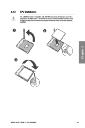
Ensure you use a CPU designed for the AM4 socket. The CPU fits in only one correct orientation. DO NOT force the CPU into the socket to prevent bending the connectors on the socket and damaging the CPU! 1 2 3 Chapter 2 ASUS ROG STRIX X570-E GAMING 2-3 2.1.2 CPU installation The AMD AM4 socket is compatible with AMD AM4 processors.
Ensure you use a CPU designed for the AM4 socket. The CPU fits in only one correct orientation. DO NOT force the CPU into the socket to prevent bending the connectors on the socket and damaging the CPU! 1 2 3 Chapter 2 ASUS ROG STRIX X570-E GAMING 2-3 2.1.2 CPU installation The AMD AM4 socket is compatible with AMD AM4 processors.
Users Manual English
Page 41
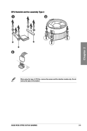
Do not remove the plate on the bottom. Chapter 2 ASUS ROG STRIX X570-E GAMING 2-5 CPU Heatsink and fan assembly Type 2 1 2 3 When using this type of CPU fan, remove the screws and the retention module only.
Do not remove the plate on the bottom. Chapter 2 ASUS ROG STRIX X570-E GAMING 2-5 CPU Heatsink and fan assembly Type 2 1 2 3 When using this type of CPU fan, remove the screws and the retention module only.
Users Manual English
Page 43
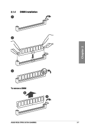
2.1.4 DIMM installation Chapter 2 To remove a DIMM ASUS ROG STRIX X570-E GAMING 2-7
2.1.4 DIMM installation Chapter 2 To remove a DIMM ASUS ROG STRIX X570-E GAMING 2-7
Users Manual English
Page 45
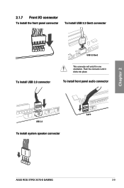
To install front panel audio connector USB 2.0 AAFP To install system speaker connector ASUS ROG STRIX X570-E GAMING 2-9 Chapter 2 2.1.7 Front I/O connector To install the front panel connector To install USB 3.2 Gen2 connector To install USB 2.0 connector USB 3.2 Gen2 This connector will only fit in one orientation. Push the connector until it clicks into place.
To install front panel audio connector USB 2.0 AAFP To install system speaker connector ASUS ROG STRIX X570-E GAMING 2-9 Chapter 2 2.1.7 Front I/O connector To install the front panel connector To install USB 3.2 Gen2 connector To install USB 2.0 connector USB 3.2 Gen2 This connector will only fit in one orientation. Push the connector until it clicks into place.

Users Manual English
Page 47
Chapter 2 2.1.9 M.2 installation Supported M.2 type varies per motherboard. M.2 installation 3 3 4 4 5 5 6 6 3 3 4 4 5 5 6 6 3 4 5 Before securing the motherboard to the chassis, please remove the PCH cover first 6 and then the M.2 heatsink. ASUS ROG STRIX X570-E GAMING 2-11
Chapter 2 2.1.9 M.2 installation Supported M.2 type varies per motherboard. M.2 installation 3 3 4 4 5 5 6 6 3 3 4 4 5 5 6 6 3 4 5 Before securing the motherboard to the chassis, please remove the PCH cover first 6 and then the M.2 heatsink. ASUS ROG STRIX X570-E GAMING 2-11

Users Manual English
Page 49
...device to save the latest BIOS version for five seconds and turns into a solid light, this means that the BIOS updating process is completed. ASUS ROG STRIX X570-E GAMING 2-13 2.2 BIOS update utility USB BIOS Flashback USB BIOS Flashback allows you to use USB BIOS Flashback: 1. We recommend you to boot up..., please contact your local ASUS Service Center. For more BIOS update utilities in BIOS setup, refer to the USB port, press the USB BIOS Flashback button for three...
...device to save the latest BIOS version for five seconds and turns into a solid light, this means that the BIOS updating process is completed. ASUS ROG STRIX X570-E GAMING 2-13 2.2 BIOS update utility USB BIOS Flashback USB BIOS Flashback allows you to use USB BIOS Flashback: 1. We recommend you to boot up..., please contact your local ASUS Service Center. For more BIOS update utilities in BIOS setup, refer to the USB port, press the USB BIOS Flashback button for three...

Users Manual English
Page 51
... Speaker Out Mic In Center/Sub woofer Rear Speaker Out 7.1-channel Side Speaker Out Front Speaker Out Mic In Center/Sub woofer Rear Speaker Out ASUS ROG STRIX X570-E GAMING 2-15 Chapter 2 * LAN port LED indications Activity Link LED Status Description OFF ORANGE No link Linked BLINKING Data activity Speed LED Status Description OFF 10...
... Speaker Out Mic In Center/Sub woofer Rear Speaker Out 7.1-channel Side Speaker Out Front Speaker Out Mic In Center/Sub woofer Rear Speaker Out ASUS ROG STRIX X570-E GAMING 2-15 Chapter 2 * LAN port LED indications Activity Link LED Status Description OFF ORANGE No link Linked BLINKING Data activity Speed LED Status Description OFF 10...

Users Manual English
Page 53
Connect to 4-channel Speakers Connect to 5.1-channel Speakers Chapter 2 Connect to 7.1-channel Speakers ASUS ROG STRIX X570-E GAMING 2-17
Connect to 4-channel Speakers Connect to 5.1-channel Speakers Chapter 2 Connect to 7.1-channel Speakers ASUS ROG STRIX X570-E GAMING 2-17


