
Users Manual English
Page 2
...LIKE), EVEN IF ASUS HAS BEEN ADVISED OF THE POSSIBILITY OF SUCH DAMAGES ARISING FROM ANY DEFECT OR ERROR IN THIS MANUAL OR PRODUCT. SPECIFICATIONS AND INFORMATION CONTAINED IN THIS MANUAL ARE FURNISHED FOR INFORMATIONAL USE ONLY, AND ARE SUBJECT TO CHANGE AT ANY TIME ...downloading it from https://www.asus.com/support/ or (2) for backup purposes, without the express written permission of reproduction and shipment, which is licensed under the General Public License ("GPL"), under various Free Open Source Software licenses. ASUSTeK is eager to Provide Source Code of the product is repaired...
...LIKE), EVEN IF ASUS HAS BEEN ADVISED OF THE POSSIBILITY OF SUCH DAMAGES ARISING FROM ANY DEFECT OR ERROR IN THIS MANUAL OR PRODUCT. SPECIFICATIONS AND INFORMATION CONTAINED IN THIS MANUAL ARE FURNISHED FOR INFORMATIONAL USE ONLY, AND ARE SUBJECT TO CHANGE AT ANY TIME ...downloading it from https://www.asus.com/support/ or (2) for backup purposes, without the express written permission of reproduction and shipment, which is licensed under the General Public License ("GPL"), under various Free Open Source Software licenses. ASUSTeK is eager to Provide Source Code of the product is repaired...
Users Manual English
Page 8
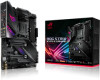
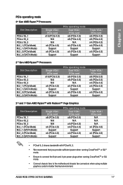
....asus.com for the Memory QVL (Qualified Vendors List). 3rd Gen AMD Ryzen™ Processors 2 x PCIe 4.0 x16 SafeSlots (supports x16, x8/x8) 2nd Gen AMD Ryzen™ Processors 2 x PCIe 3.0 x16 SafeSlots (supports x16, x8/x8) 2nd and 1st Gen AMD Ryzen™ with Radeon™ Vega Graphics Processors 1 x PCIe 3.0 x16 SafeSlot (supports x8 ) AMD X570 chipset 1 x PCIe 4.0 x16 (supports x4) 2 x PCIe 4.0 x 1 slots * The PCIe x16_3 slot shares bandwidth with PCIe x1_2. ROG STRIX X570-E GAMING specifications summary CPU Chipset Memory Expansion slots Graphics Multi-GPU support AMD AM4 Socket...
....asus.com for the Memory QVL (Qualified Vendors List). 3rd Gen AMD Ryzen™ Processors 2 x PCIe 4.0 x16 SafeSlots (supports x16, x8/x8) 2nd Gen AMD Ryzen™ Processors 2 x PCIe 3.0 x16 SafeSlots (supports x16, x8/x8) 2nd and 1st Gen AMD Ryzen™ with Radeon™ Vega Graphics Processors 1 x PCIe 3.0 x16 SafeSlot (supports x8 ) AMD X570 chipset 1 x PCIe 4.0 x16 (supports x4) 2 x PCIe 4.0 x 1 slots * The PCIe x16_3 slot shares bandwidth with PCIe x1_2. ROG STRIX X570-E GAMING specifications summary CPU Chipset Memory Expansion slots Graphics Multi-GPU support AMD AM4 Socket...

Users Manual English
Page 11
... 3 for M Key, type 2242/2260/2280/22110 devices (support PCIE and SATA modes) 1 x 4-Pin CPU_FAN connector 1 x 4-Pin CPU_OPT fan connector 1 x 4-Pin AIO_PUMP connector 1 x 4-Pin W_PUMP+ connector 2 x 4-Pin CHA_FAN connectors 1 x 4-Pin M.2_FAN connector 1 x PCH _FAN connector 1 x T_ SENSOR connector 2 x AURA Addressable Gen2 headers 2 x AURA RGB headers 1 x 24-pin EATX power connector 1 x 8-pin EATX 12V power connector 1 x 4-pin EATX 12V power connector 1 x System panel connector 1 x Front panel audio connector (AAFP) 1 x Clear CMOS jumper (2-pin) (continued on LAN, Audio, KBMS and USB ports...
... 3 for M Key, type 2242/2260/2280/22110 devices (support PCIE and SATA modes) 1 x 4-Pin CPU_FAN connector 1 x 4-Pin CPU_OPT fan connector 1 x 4-Pin AIO_PUMP connector 1 x 4-Pin W_PUMP+ connector 2 x 4-Pin CHA_FAN connectors 1 x 4-Pin M.2_FAN connector 1 x PCH _FAN connector 1 x T_ SENSOR connector 2 x AURA Addressable Gen2 headers 2 x AURA RGB headers 1 x 24-pin EATX power connector 1 x 8-pin EATX 12V power connector 1 x 4-pin EATX 12V power connector 1 x System panel connector 1 x Front panel audio connector (AAFP) 1 x Clear CMOS jumper (2-pin) (continued on LAN, Audio, KBMS and USB ports...
Users Manual English
Page 15
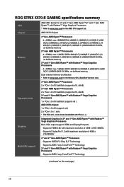
... them. • Whenever you uninstall any component, place it on a grounded antistatic pad or in the bag that came with the component. • Before you install or remove any component, ensure that the ATX power supply is switched off or the power cord is detached from the power supply. ASUS ROG STRIX X570-E GAMING 1-1
... them. • Whenever you uninstall any component, place it on a grounded antistatic pad or in the bag that came with the component. • Before you install or remove any component, ensure that the ATX power supply is switched off or the power cord is detached from the power supply. ASUS ROG STRIX X570-E GAMING 1-1
Users Manual English
Page 17
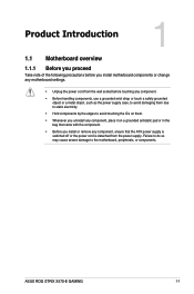
...; Q-Code LED 19. water pump+, M.2 fan, and AIO pump connectors (4-pin CPU_FAN, 4-pin CPU_OPT, 4-pin CHA_FAN12; 4-pin W_PUMP+, 4-pin M.2_FAN, 4-pin AIO_PUMP) 3. AM4 CPU socket 5. DDR4 DIMM slots 7. System panel connectors (10-1 pin PANEL, 4-pin SPEAKER) 14. USB 2.0 connectors (10-1 pin USB12, USB34) 16. Front panel audio connector (10-1 pin AAFP) 20. PCH fan connectors (4-pin PCH_FAN) 24. BIOS Flashback button (BIOS_FLBK) Page 1-19 1-18 1-21 1-4 1-11 1-4 1-8 1-12 1-15 1-20 1-10 1-14 1-17 1-15 1-16 1-13 1-21 1-8 1-13 1-6 1-6 1-9 1-22 1-16 1-9 2-13 ASUS ROG STRIX X570-E GAMING 1-3
...; Q-Code LED 19. water pump+, M.2 fan, and AIO pump connectors (4-pin CPU_FAN, 4-pin CPU_OPT, 4-pin CHA_FAN12; 4-pin W_PUMP+, 4-pin M.2_FAN, 4-pin AIO_PUMP) 3. AM4 CPU socket 5. DDR4 DIMM slots 7. System panel connectors (10-1 pin PANEL, 4-pin SPEAKER) 14. USB 2.0 connectors (10-1 pin USB12, USB34) 16. Front panel audio connector (10-1 pin AAFP) 20. PCH fan connectors (4-pin PCH_FAN) 24. BIOS Flashback button (BIOS_FLBK) Page 1-19 1-18 1-21 1-4 1-11 1-4 1-8 1-12 1-15 1-20 1-10 1-14 1-17 1-15 1-16 1-13 1-21 1-8 1-13 1-6 1-6 1-9 1-22 1-16 1-9 2-13 ASUS ROG STRIX X570-E GAMING 1-3

Users Manual English
Page 19
... mapped for the dual-channel configuration. ASUS ROG STRIX X570-E GAMING 1-5 Chapter 1 Recommended memory configurations Memory configurations You may install 2 GB, 4 GB, 8 GB, and 16 GB unbuffered DDR4 DIMMs into the DIMM sockets. • You may operate at a lower frequency than the vendor-marked value. • For system stability, use a more efficient memory cooling system to get the correct memory modules. Any excess memory from the higher-sized channel is the...
... mapped for the dual-channel configuration. ASUS ROG STRIX X570-E GAMING 1-5 Chapter 1 Recommended memory configurations Memory configurations You may install 2 GB, 4 GB, 8 GB, and 16 GB unbuffered DDR4 DIMMs into the DIMM sockets. • You may operate at a lower frequency than the vendor-marked value. • For system stability, use a more efficient memory cooling system to get the correct memory modules. Any excess memory from the higher-sized channel is the...
Users Manual English
Page 21
... mode Dual VGA / PCIe card x8 (PCIe 3.0) N/A x4 (PCIe 4.0) x4 (PCIe 4.0) Support x4 (PCIe 4.0) Support Triple VGA / PCIe card N/A N/A N/A x4 (PCIe 4.0) Support x4 (PCIe 4.0) Support • PCIex16_2 shares bandwidth with PCIex16_3. • We recommend that you provide sufficient power when running CrossFireXTM or SLI® mode. • Ensure to connect the 8-pin and 4-pin power plugs when running CrossFireXTM or SLI mode. • Connect chassis fans to the motherboard chassis fan connectors when using multiple graphics cards for better thermal environment. ASUS ROG STRIX X570-E GAMING...
... mode Dual VGA / PCIe card x8 (PCIe 3.0) N/A x4 (PCIe 4.0) x4 (PCIe 4.0) Support x4 (PCIe 4.0) Support Triple VGA / PCIe card N/A N/A N/A x4 (PCIe 4.0) Support x4 (PCIe 4.0) Support • PCIex16_2 shares bandwidth with PCIex16_3. • We recommend that you provide sufficient power when running CrossFireXTM or SLI® mode. • Ensure to connect the 8-pin and 4-pin power plugs when running CrossFireXTM or SLI mode. • Connect chassis fans to the motherboard chassis fan connectors when using multiple graphics cards for better thermal environment. ASUS ROG STRIX X570-E GAMING...

Users Manual English
Page 27
... that supports HD Audio. AGND NC SENSE1_RETUR SENSE2_RETUR STRIX X570-e GAMING AAFP PORT1 L PORT1 R PORT2 R SENSE_SEND PORT2 L HD-audio-compliant pin definition ROG STRIX X570-E GAMING Analog front panel connector We recommend that monitors the temperature of the motherboard's high-definition audio capability. STRIX X570-e GAMING T_SENSOR GND PIN 1 SENSOR IN ROG STRIX X570-E GAMING T_SENSOR connector 1.1.8 Internal connectors 1. ASUS ROG STRIX X570-E GAMING 1-13 Front panel audio connector (10-1 pin AAFP) This connector is for a chassis-mounted front panel audio I /O module cable to...
... that supports HD Audio. AGND NC SENSE1_RETUR SENSE2_RETUR STRIX X570-e GAMING AAFP PORT1 L PORT1 R PORT2 R SENSE_SEND PORT2 L HD-audio-compliant pin definition ROG STRIX X570-E GAMING Analog front panel connector We recommend that monitors the temperature of the motherboard's high-definition audio capability. STRIX X570-e GAMING T_SENSOR GND PIN 1 SENSOR IN ROG STRIX X570-E GAMING T_SENSOR connector 1.1.8 Internal connectors 1. ASUS ROG STRIX X570-E GAMING 1-13 Front panel audio connector (10-1 pin AAFP) This connector is for a chassis-mounted front panel audio I /O module cable to...

Users Manual English
Page 31
... is ON turns the system OFF. • Reset button (2-pin RESET) This 2-pin connector is for the chassis-mounted reset button for the HDD Activity LED. The system power LED lights up or flashes when data is read from or written to this connector. Connect the HDD Activity LED cable to the HDD. • System warning speaker (4-pin SPEAKER) This 4-pin connector is for the chassis-mounted system warning speaker. ASUS ROG STRIX X570-E GAMING 1-17 STRIX X570-e GAMING ROG STRIX X570-E GAMING SPEAKER & F_PANEL connectors • System power LED (2-pin PLED) This 2-pin connector is for...
... is ON turns the system OFF. • Reset button (2-pin RESET) This 2-pin connector is for the chassis-mounted reset button for the HDD Activity LED. The system power LED lights up or flashes when data is read from or written to this connector. Connect the HDD Activity LED cable to the HDD. • System warning speaker (4-pin SPEAKER) This 4-pin connector is for the chassis-mounted system warning speaker. ASUS ROG STRIX X570-E GAMING 1-17 STRIX X570-e GAMING ROG STRIX X570-E GAMING SPEAKER & F_PANEL connectors • System power LED (2-pin PLED) This 2-pin connector is for...
Users Manual English
Page 39
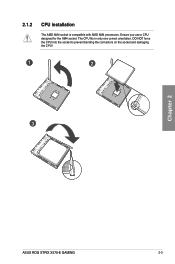
Ensure you use a CPU designed for the AM4 socket. DO NOT force the CPU into the socket to prevent bending the connectors on the socket and damaging the CPU! 1 2 3 Chapter 2 ASUS ROG STRIX X570-E GAMING 2-3 The CPU fits in only one correct orientation. 2.1.2 CPU installation The AMD AM4 socket is compatible with AMD AM4 processors.
Ensure you use a CPU designed for the AM4 socket. DO NOT force the CPU into the socket to prevent bending the connectors on the socket and damaging the CPU! 1 2 3 Chapter 2 ASUS ROG STRIX X570-E GAMING 2-3 The CPU fits in only one correct orientation. 2.1.2 CPU installation The AMD AM4 socket is compatible with AMD AM4 processors.

Users Manual English
Page 49
.... If this motherboard. 3. 2.2 BIOS update utility USB BIOS Flashback USB BIOS Flashback allows you to boot up, please contact your local ASUS Service Center. Shut down your computer. 5. To use a USB 2.0 storage device to the section Updating BIOS in BIOS setup, refer to save the latest BIOS version for this scenario happens, please restart the system to the USB Flashback port. Visit https://www.asus.com/support/ and download the latest BIOS version for better compatibility and stability. 2. ASUS ROG STRIX X570-E GAMING 2-13...
.... If this motherboard. 3. 2.2 BIOS update utility USB BIOS Flashback USB BIOS Flashback allows you to boot up, please contact your local ASUS Service Center. Shut down your computer. 5. To use a USB 2.0 storage device to the section Updating BIOS in BIOS setup, refer to save the latest BIOS version for this scenario happens, please restart the system to the USB Flashback port. Visit https://www.asus.com/support/ and download the latest BIOS version for better compatibility and stability. 2. ASUS ROG STRIX X570-E GAMING 2-13...

Users Manual English
Page 53
Connect to 4-channel Speakers Connect to 5.1-channel Speakers Chapter 2 Connect to 7.1-channel Speakers ASUS ROG STRIX X570-E GAMING 2-17
Connect to 4-channel Speakers Connect to 5.1-channel Speakers Chapter 2 Connect to 7.1-channel Speakers ASUS ROG STRIX X570-E GAMING 2-17

Users Manual English
Page 69
... PCIe Lanes and configure onboard devices. Chapter 3 ASUS ROG STRIX X570-E GAMING 3-15 Configuration options: [Disabled] [Enabled] 3.6.5 Onboard Devices Configuration The items in working state. When a device (with bandwidth >= 4X) is inserted into PCIEX16_3 and no device or SATA mode M.2 device is inserted to M.2_2, whenever PCIEx1_1 or PCIEx1_3 is inserted to M.2_2, switches PCIEx16_3 to X4 mode; RGB LED lighting When system is in this menu allow you to turn the RGB LED lighting on or off Q-Code LED. [POST Code Only] Show POST (POWER...
... PCIe Lanes and configure onboard devices. Chapter 3 ASUS ROG STRIX X570-E GAMING 3-15 Configuration options: [Disabled] [Enabled] 3.6.5 Onboard Devices Configuration The items in working state. When a device (with bandwidth >= 4X) is inserted into PCIEX16_3 and no device or SATA mode M.2 device is inserted to M.2_2, whenever PCIEx1_1 or PCIEx1_3 is inserted to M.2_2, switches PCIEx16_3 to X4 mode; RGB LED lighting When system is in this menu allow you to turn the RGB LED lighting on or off Q-Code LED. [POST Code Only] Show POST (POWER...

Users Manual English
Page 70
...] Realtek 2.5G LAN Controller This item allows you to enable or disable the RTC (Real-Time Clock) to switch off . ErP Ready [Disabled] This item allows you can set system wake and sleep settings. Configuration options: [Disabled] [Enabled] Chapter 3 3-16 Chapter 3: BIOS Setup Configuration options: [Disabled] [Enable(S4+S5)] [Enable(S5)] Restore AC Power Loss This item allows your system to [Last State], it goes to enable or disable the Realtek 2.5G LAN controllers. Configuration options: [Disabled] [Enabled] Power On By RTC...
...] Realtek 2.5G LAN Controller This item allows you to enable or disable the RTC (Real-Time Clock) to switch off . ErP Ready [Disabled] This item allows you can set system wake and sleep settings. Configuration options: [Disabled] [Enabled] Chapter 3 3-16 Chapter 3: BIOS Setup Configuration options: [Disabled] [Enable(S4+S5)] [Enable(S5)] Restore AC Power Loss This item allows your system to [Last State], it goes to enable or disable the Realtek 2.5G LAN controllers. Configuration options: [Disabled] [Enabled] Power On By RTC...

Users Manual English
Page 71
... SMART Information This menu displays the SMART information of the USB ports. ASUS ROG STRIX X570-E GAMING 3-17 Legacy USB Support [Enabled] Your system supports the USB devices in legacy operating systems. [Disabled] Your USB devices can be recognized in the boot devices list. [Auto] Your system automatically detects the presence of USB devices at startup. Configuration options: [Disabled] [Enabled] USB Single Port Control This item allows you to enable or disable the Single Root IO Virtualization support if your system has SR-IOV capable PCIe devices. 3.6.7 PCI Subsytem Settings...
... SMART Information This menu displays the SMART information of the USB ports. ASUS ROG STRIX X570-E GAMING 3-17 Legacy USB Support [Enabled] Your system supports the USB devices in legacy operating systems. [Disabled] Your USB devices can be recognized in the boot devices list. [Auto] Your system automatically detects the presence of USB devices at startup. Configuration options: [Disabled] [Enabled] USB Single Port Control This item allows you to enable or disable the Single Root IO Virtualization support if your system has SR-IOV capable PCIe devices. 3.6.7 PCI Subsytem Settings...

Users Manual English
Page 72
... various VGA, bootable devices and add-on devices for each fan. 3.8 Boot menu The Boot menu items allow you to [Enabled]. Configuration options: [Ignore] [Legacy only] [UEFI only] Chapter 3 3-18 Chapter 3: BIOS Setup CSM (Compatibility Support Module) This item allows you to launch. Boot Device Control [UEFI and Legacy OPROM] This item allows you to select the type of network devices that you want to change the fan settings. Launch CSM [Enabled] [Disabled] For better compatibility, enable the CSM to boot. Configuration options: [UEFI and Legacy OPROM] [Legacy...
... various VGA, bootable devices and add-on devices for each fan. 3.8 Boot menu The Boot menu items allow you to [Enabled]. Configuration options: [Ignore] [Legacy only] [UEFI only] Chapter 3 3-18 Chapter 3: BIOS Setup CSM (Compatibility Support Module) This item allows you to launch. Boot Device Control [UEFI and Legacy OPROM] This item allows you to select the type of network devices that you want to change the fan settings. Launch CSM [Enabled] [Disabled] For better compatibility, enable the CSM to boot. Configuration options: [UEFI and Legacy OPROM] [Legacy...

Users Manual English
Page 73
... items displays the available devices. Chapter 3 ASUS ROG STRIX X570-E GAMING 3-19 Boot from the selected device. 3.9 Tool menu The Tool menu items allow you to configure options for special functions. Click an item to start booting from PCI-E/PCI Expansion Devices [Legacy only] This item allows you to select the type of devices installed in Safe Mode, press after POST. • To select the boot device during POST. When you to configure the Windows® Secure Boot settings and manage its keys...
... items displays the available devices. Chapter 3 ASUS ROG STRIX X570-E GAMING 3-19 Boot from the selected device. 3.9 Tool menu The Tool menu items allow you to configure options for special functions. Click an item to start booting from PCI-E/PCI Expansion Devices [Legacy only] This item allows you to select the type of devices installed in Safe Mode, press after POST. • To select the boot device during POST. When you to configure the Windows® Secure Boot settings and manage its keys...

Users Manual English
Page 79
... BIOS file and enters ASUS EZ Flash 3 automatically. 4. Chapter 3 ASUS ROG STRIX X570-E GAMING 3-25 To ensure system compatibility and stability, we recommend that allows you to restore the BIOS file when it to a USB flash drive. Doing so can restore a corrupted BIOS file using the motherboard support DVD or a USB flash drive that contains the BIOS file. Turn on the ASUS official website. DO NOT shut down or reset the system while updating the BIOS! 3.11.3 ASUS CrashFree BIOS 3 The ASUS CrashFree BIOS 3 utility is an auto recovery...
... BIOS file and enters ASUS EZ Flash 3 automatically. 4. Chapter 3 ASUS ROG STRIX X570-E GAMING 3-25 To ensure system compatibility and stability, we recommend that allows you to restore the BIOS file when it to a USB flash drive. Doing so can restore a corrupted BIOS file using the motherboard support DVD or a USB flash drive that contains the BIOS file. Turn on the ASUS official website. DO NOT shut down or reset the system while updating the BIOS! 3.11.3 ASUS CrashFree BIOS 3 The ASUS CrashFree BIOS 3 utility is an auto recovery...

Users Manual English
Page 85
... is started IDE Reset IDE Detect IDE Enable SCSI initialization is started SCSI Reset SCSI Detect SCSI Enable Setup Verifying Password Start of Setup Reserved for ASL (see ASL Status Codes section below) Setup Input Wait Reserved for ASL (see ASL Status Codes section below) Ready To Boot event Legacy Boot event Exit Boot Services event Runtime Set Virtual Address MAP Begin Runtime Set Virtual Address MAP End Legacy Option ROM Initialization System Reset (continued on the next page) ASUS ROG STRIX X570-E GAMING A-3
... is started IDE Reset IDE Detect IDE Enable SCSI initialization is started SCSI Reset SCSI Detect SCSI Enable Setup Verifying Password Start of Setup Reserved for ASL (see ASL Status Codes section below) Setup Input Wait Reserved for ASL (see ASL Status Codes section below) Ready To Boot event Legacy Boot event Exit Boot Services event Runtime Set Virtual Address MAP Begin Runtime Set Virtual Address MAP End Legacy Option ROM Initialization System Reset (continued on the next page) ASUS ROG STRIX X570-E GAMING A-3

Users Manual English
Page 86
... into ACPI mode. Interrupt controller is in APIC mode. Appendix Q-Code table Code B4 B5 B6 B7 B8- BF D0 D1 D2 D3 D4 D5 D6 D7 D8 D9 DA DB DC Description USB hot plug PCI bus hot plug Clean-up from the S3 sleep state System is waking up of NVRAM Configuration Reset (reset of NVRAM settings) Reserved for future AMI codes CPU initialization error System Agent initialization error...
... into ACPI mode. Interrupt controller is in APIC mode. Appendix Q-Code table Code B4 B5 B6 B7 B8- BF D0 D1 D2 D3 D4 D5 D6 D7 D8 D9 DA DB DC Description USB hot plug PCI bus hot plug Clean-up from the S3 sleep state System is waking up of NVRAM Configuration Reset (reset of NVRAM settings) Reserved for future AMI codes CPU initialization error System Agent initialization error...


