User Guide
Page 15
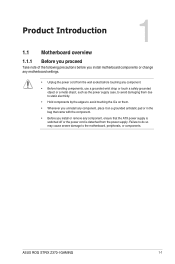
... as the power supply case, to avoid damaging them due to static electricity. • Hold components by the edges to the motherboard, peripherals, or components. ASUS ROG STRIX Z370-I GAMING 1-1
... as the power supply case, to avoid damaging them due to static electricity. • Hold components by the edges to the motherboard, peripherals, or components. ASUS ROG STRIX Z370-I GAMING 1-1
User Guide
Page 17
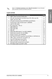
... 1-13 1-11 1-12 1-8 1-13 1-11 1-9 ASUS ROG STRIX Z370-I /O connection for more information about rear panel connectors and internal connectors. Thermal sensor cable connector (2-pin T_SENSOR) 5. M.2_2) 7. M.2 sockets (M.2_1; RGB LED 10. POST State LEDs 9. Clear RTC RAM jumper (2-pin CLRTC) 16. Chapter 1 Refer to 1.1.8 Internal connectors and 2.2.1 Rear I GAMING 1-3 Speaker connector (4-pin SPEAKER) 13...
... 1-13 1-11 1-12 1-8 1-13 1-11 1-9 ASUS ROG STRIX Z370-I /O connection for more information about rear panel connectors and internal connectors. Thermal sensor cable connector (2-pin T_SENSOR) 5. M.2_2) 7. M.2 sockets (M.2_1; RGB LED 10. POST State LEDs 9. Clear RTC RAM jumper (2-pin CLRTC) 16. Chapter 1 Refer to 1.1.8 Internal connectors and 2.2.1 Rear I GAMING 1-3 Speaker connector (4-pin SPEAKER) 13...
User Guide
Page 19
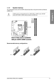
DO NOT install a DDR, DDR2, or DDR3 memory module to the DDR4 slot. ROG STRIX Z370-I GAMING 288-pin DDR4 DIMM sockets Recommended memory configurations ASUS ROG STRIX Z370-I GAMING 1-5 A DDR4 module is notched differently from a DDR, DDR2, or DDR3 module. DIMM_A1 DIMM_B1 Chapter 1 1.1.4 System memory The motherboard comes with two DDR4 (Double Data Rate 4) Quad Inline Memory Modules (DIMM) slots.
DO NOT install a DDR, DDR2, or DDR3 memory module to the DDR4 slot. ROG STRIX Z370-I GAMING 288-pin DDR4 DIMM sockets Recommended memory configurations ASUS ROG STRIX Z370-I GAMING 1-5 A DDR4 module is notched differently from a DDR, DDR2, or DDR3 module. DIMM_A1 DIMM_B1 Chapter 1 1.1.4 System memory The motherboard comes with two DDR4 (Double Data Rate 4) Quad Inline Memory Modules (DIMM) slots.
User Guide
Page 21
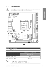
ASUS ROG STRIX Z370-I /O T_SENSOR 128Mb BIOS AUDIO AAFP 2280 TPU 2260 USB1112 CHA_FAN Intel® Z370 PCIEX16_1 1 M.2_1(SOCKET3) M.2_2(SOCKET3)Bottom CLRTC PCIE SATA IRST X4 V V Slot No. Slot Description 1 PCIE_x16 slot Hyper M.2 X16 card configuration 2 Intel® ... (64bit, 288-pin module) SATA6G_2 SATA6G_1 SPEAKER F_PANEL ADD_HEADER U31G1_12 SATA6G_4 SATA6G_3 HDMI_DP LGA1151 LAN_U31G1_34 AIO_PUMP M.2(WIFI) Intel® (Bottom) I219V BATT_CON Super I GAMING 1-7 Chapter 1 1.1.5 Expansion slots Unplug the power cord before adding or removing expansion cards.
ASUS ROG STRIX Z370-I /O T_SENSOR 128Mb BIOS AUDIO AAFP 2280 TPU 2260 USB1112 CHA_FAN Intel® Z370 PCIEX16_1 1 M.2_1(SOCKET3) M.2_2(SOCKET3)Bottom CLRTC PCIE SATA IRST X4 V V Slot No. Slot Description 1 PCIE_x16 slot Hyper M.2 X16 card configuration 2 Intel® ... (64bit, 288-pin module) SATA6G_2 SATA6G_1 SPEAKER F_PANEL ADD_HEADER U31G1_12 SATA6G_4 SATA6G_3 HDMI_DP LGA1151 LAN_U31G1_34 AIO_PUMP M.2(WIFI) Intel® (Bottom) I219V BATT_CON Super I GAMING 1-7 Chapter 1 1.1.5 Expansion slots Unplug the power cord before adding or removing expansion cards.

User Guide
Page 23
BATT_CON PIN 1 ROG STRIX Z370-I GAMING BATT_CON ASUS ROG STRIX Z370-I GAMING 1-9 RTC Battery header (2-pin BATT_CON) This header is for the lithium CMOS battery. GND VBAT Chapter 1 2.
BATT_CON PIN 1 ROG STRIX Z370-I GAMING BATT_CON ASUS ROG STRIX Z370-I GAMING 1-9 RTC Battery header (2-pin BATT_CON) This header is for the lithium CMOS battery. GND VBAT Chapter 1 2.
User Guide
Page 25
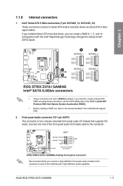
... RSATA_RXN3 RSATA_RXP3 GND A SATA6G_2 SATA6G_4 GND GND RSATA_TXP2 RSATA_TXP4 B RSATA_TXN2 GND RSATA_TXN4 GND RSATA_RXN2 RSATA_RXN4 RSATA_RXP2 RSATA_RXP4 GND GND ROG STRIX Z370-I GAMING Analog front panel connector We recommend that supports HD Audio. AAFP SENSE2_RETUR SENSE1_RETUR NC AGND PORT2 L SENSE_SEND PORT2 R PORT1...Front panel audio connector (10-1 pin AAFP) This connector is for a chassis-mounted front panel audio I GAMING 1-11 ASUS ROG STRIX Z370-I /O module that you can create a RAID 0, 1, 5, and 10 configuration with the Intel® Rapid Storage Technology through ...
... RSATA_RXN3 RSATA_RXP3 GND A SATA6G_2 SATA6G_4 GND GND RSATA_TXP2 RSATA_TXP4 B RSATA_TXN2 GND RSATA_TXN4 GND RSATA_RXN2 RSATA_RXN4 RSATA_RXP2 RSATA_RXP4 GND GND ROG STRIX Z370-I GAMING Analog front panel connector We recommend that supports HD Audio. AAFP SENSE2_RETUR SENSE1_RETUR NC AGND PORT2 L SENSE_SEND PORT2 R PORT1...Front panel audio connector (10-1 pin AAFP) This connector is for a chassis-mounted front panel audio I GAMING 1-11 ASUS ROG STRIX Z370-I /O module that you can create a RAID 0, 1, 5, and 10 configuration with the Intel® Rapid Storage Technology through ...
User Guide
Page 27
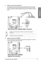
... and warnings. Chapter 1 USB+5V USB_P11USB_P11+ GND NC USB+5V USB_P12USB_P12+ GND USB1112 PIN 1 ROG STRIX Z370-I GAMING 1-13 Speaker connector (4-pin SPEAKER) The 4-pin connector is for USB 2.0 ports. SPEAKER Speaker Out GND GND +5V PIN 1 ROG STRIX Z370-I GAMING Speaker Out connector ASUS ROG STRIX Z370-I GAMING USB2.0 connector DO NOT connect a 1394 cable to 480 Mb/s connection speed. Connect the...
... and warnings. Chapter 1 USB+5V USB_P11USB_P11+ GND NC USB+5V USB_P12USB_P12+ GND USB1112 PIN 1 ROG STRIX Z370-I GAMING 1-13 Speaker connector (4-pin SPEAKER) The 4-pin connector is for USB 2.0 ports. SPEAKER Speaker Out GND GND +5V PIN 1 ROG STRIX Z370-I GAMING Speaker Out connector ASUS ROG STRIX Z370-I GAMING USB2.0 connector DO NOT connect a 1394 cable to 480 Mb/s connection speed. Connect the...
User Guide
Page 29
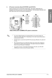
... Power OK -5 Volts GND PIN 1 +5 Volts GND GND GND GND GND GND GND GND +5 Volts PSON# GND GND +3 Volts -12 Volts +3 Volts +3 Volts PIN 1 ROG STRIX Z370-I GAMING 1-15 ASUS ROG STRIX Z370-I GAMING ATX power connectors • For a fully configured system, we recommend that complies with ATX 12 V Specification 2.0 (or later version) and provides a minimum power of 350...
... Power OK -5 Volts GND PIN 1 +5 Volts GND GND GND GND GND GND GND GND +5 Volts PSON# GND GND +3 Volts -12 Volts +3 Volts +3 Volts PIN 1 ROG STRIX Z370-I GAMING 1-15 ASUS ROG STRIX Z370-I GAMING ATX power connectors • For a fully configured system, we recommend that complies with ATX 12 V Specification 2.0 (or later version) and provides a minimum power of 350...
User Guide
Page 31
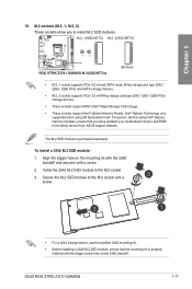
Before using 8th Generation Intel® Processors. ASUS ROG STRIX Z370-I GAMING M.2(SOCKET3)s (Bottom) • M.2_1 socket supports PCIe 3.0 x4 and SATA mode M Key design and type 2242 / 2260 / 2280 PCIe and SATA storage devices. ...a 2242 M.2 SSD module, ensure that you to the M.2 socket. 3. Align the bigger hole on the 2260 standoff. Chapter 1 10. M.2_1(SOCKET3) M.2_2(SOCKET3) 2280 2260 ROG STRIX Z370-I GAMING 1-17 To install a 2242 M.2 SSD module: 1. Secure the M.2 SSD module to the M.2 socket with a screw. 2. Install the 2242 M.2 SSD module to install M.2 SSD...
Before using 8th Generation Intel® Processors. ASUS ROG STRIX Z370-I GAMING M.2(SOCKET3)s (Bottom) • M.2_1 socket supports PCIe 3.0 x4 and SATA mode M Key design and type 2242 / 2260 / 2280 PCIe and SATA storage devices. ...a 2242 M.2 SSD module, ensure that you to the M.2 socket. 3. Align the bigger hole on the 2260 standoff. Chapter 1 10. M.2_1(SOCKET3) M.2_2(SOCKET3) 2280 2260 ROG STRIX Z370-I GAMING 1-17 To install a 2242 M.2 SSD module: 1. Secure the M.2 SSD module to the M.2 socket with a screw. 2. Install the 2242 M.2 SSD module to install M.2 SSD...
User Guide
Page 33
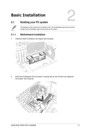
The motherboard layout may vary with models, but the installation steps are the same for reference only. Place the motherboard into the chassis, ensuring that its rear I/O ports are aligned to the chassis rear I/O panel. 2. Chapter 2 ASUS ROG STRIX Z370-I /O panel. Install the ASUS Q-Shield to the chassis' rear I GAMING 2-1 Chapter 2: Basic Installation Basic Installation 2.1 Building your PC system 2 The diagrams in this section are for all models. 2.1.1 Motherboard installation 1.
The motherboard layout may vary with models, but the installation steps are the same for reference only. Place the motherboard into the chassis, ensuring that its rear I/O ports are aligned to the chassis rear I/O panel. 2. Chapter 2 ASUS ROG STRIX Z370-I /O panel. Install the ASUS Q-Shield to the chassis' rear I GAMING 2-1 Chapter 2: Basic Installation Basic Installation 2.1 Building your PC system 2 The diagrams in this section are for all models. 2.1.1 Motherboard installation 1.
User Guide
Page 35
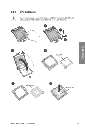
Chapter 2 Top of CPU Bottom of CPU Bottom of CPU ASUS ROG STRIX Z370-I GAMING 2-3 2.1.2 CPU installation Ensure that you install the correct CPU designed for LGA1155 and LGA1156 sockets on the LGA1151 socket. DO NOT install a CPU designed for LGA1151 socket only.
Chapter 2 Top of CPU Bottom of CPU Bottom of CPU ASUS ROG STRIX Z370-I GAMING 2-3 2.1.2 CPU installation Ensure that you install the correct CPU designed for LGA1155 and LGA1156 sockets on the LGA1151 socket. DO NOT install a CPU designed for LGA1151 socket only.
User Guide
Page 37
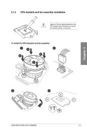
2.1.3 CPU heatsink and fan assembly installation Apply the Thermal Interface Material to the CPU heatsink and CPU before you install the heatsink and fan, if necessary. To install the CPU heatsink and fan assembly Chapter 2 ASUS ROG STRIX Z370-I GAMING 2-5
2.1.3 CPU heatsink and fan assembly installation Apply the Thermal Interface Material to the CPU heatsink and CPU before you install the heatsink and fan, if necessary. To install the CPU heatsink and fan assembly Chapter 2 ASUS ROG STRIX Z370-I GAMING 2-5
User Guide
Page 39
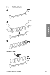
2.1.4 DIMM installation Chapter 2 To remove a DIMM ASUS ROG STRIX Z370-I GAMING 2-7
2.1.4 DIMM installation Chapter 2 To remove a DIMM ASUS ROG STRIX Z370-I GAMING 2-7
User Guide
Page 41
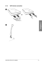
2.1.6 SATA device connection OR Chapter 2 ASUS ROG STRIX Z370-I GAMING 2-9
2.1.6 SATA device connection OR Chapter 2 ASUS ROG STRIX Z370-I GAMING 2-9

User Guide
Page 43
2.1.8 Expansion card installation To install PCIe x16 cards Chapter 2 ASUS ROG STRIX Z370-I GAMING 2-11
2.1.8 Expansion card installation To install PCIe x16 cards Chapter 2 ASUS ROG STRIX Z370-I GAMING 2-11

User Guide
Page 45
Chapter 2 ASUS ROG STRIX Z370-I /O port layout may vary with models, but the Wi-Fi antenna installation procedure is the same for reference only. The I GAMING 2-13 The illustration above is at least 20 cm away from all models. 2.1.10 Wi-Fi antenna installation Installing the ASUS 2x2 dual band W-Fi antenna Connect the bundled ASUS 2x2 dual band Wi-Fi antenna connector to the Wi-Fi ports at the back of the chassis. • Ensure that the ASUS 2x2 dual band Wi-Fi antenna is securely installed to the Wi-Fi ports. • Ensure that the antenna is for all persons.
Chapter 2 ASUS ROG STRIX Z370-I /O port layout may vary with models, but the Wi-Fi antenna installation procedure is the same for reference only. The I GAMING 2-13 The illustration above is at least 20 cm away from all models. 2.1.10 Wi-Fi antenna installation Installing the ASUS 2x2 dual band W-Fi antenna Connect the bundled ASUS 2x2 dual band Wi-Fi antenna connector to the Wi-Fi ports at the back of the chassis. • Ensure that the ASUS 2x2 dual band Wi-Fi antenna is securely installed to the Wi-Fi ports. • Ensure that the antenna is for all persons.

User Guide
Page 47
... In Front Speaker Out Mic In Center/Subwoofer Rear Speaker Out 8-channel Side speaker Front Speaker Out Mic In Center/Subwoofer Rear Speaker Out Chapter 2 ASUS ROG STRIX Z370-I GAMING 2-15 Due to hardware design, the LAN1 port's LEDs may continue to wake up then steady) from S5 mode ACT/LINK SPEED LED LED LAN...
... In Front Speaker Out Mic In Center/Subwoofer Rear Speaker Out 8-channel Side speaker Front Speaker Out Mic In Center/Subwoofer Rear Speaker Out Chapter 2 ASUS ROG STRIX Z370-I GAMING 2-15 Due to hardware design, the LAN1 port's LEDs may continue to wake up then steady) from S5 mode ACT/LINK SPEED LED LED LAN...

User Guide
Page 49
Connect to 4 channel Speakers Connect to 6 channel Speakers Chapter 2 ASUS ROG STRIX Z370-I GAMING 2-17
Connect to 4 channel Speakers Connect to 6 channel Speakers Chapter 2 ASUS ROG STRIX Z370-I GAMING 2-17

User Guide
Page 51
Chapter 2 ASUS ROG STRIX Z370-I GAMING 2-19 Press the power switch for less than four seconds to put the system on sleep mode or soft-off mode regardless of the BIOS ...
Chapter 2 ASUS ROG STRIX Z370-I GAMING 2-19 Press the power switch for less than four seconds to put the system on sleep mode or soft-off mode regardless of the BIOS ...

User Guide
Page 53
... Z370IGAM.CAP for system startup in this motherboard. The term "BIOS" in the motherboard CMOS. Chapter 3 ASUS ROG STRIX Z370-I GAMING 3-1 Inappropriate BIOS settings may result to ensure optimal performance. Chapter 3: BIOS Setup BIOS Setup 3.1 Knowing BIOS 3 The new ASUS UEFI BIOS is a Unified Extensible Interface that complies with UEFI architecture, offering a user-friendly interface that...
... Z370IGAM.CAP for system startup in this motherboard. The term "BIOS" in the motherboard CMOS. Chapter 3 ASUS ROG STRIX Z370-I GAMING 3-1 Inappropriate BIOS settings may result to ensure optimal performance. Chapter 3: BIOS Setup BIOS Setup 3.1 Knowing BIOS 3 The new ASUS UEFI BIOS is a Unified Extensible Interface that complies with UEFI architecture, offering a user-friendly interface that...


