Users Manual English
Page 15
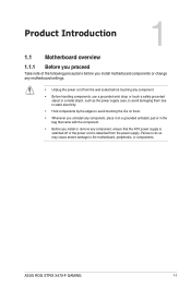
... as the power supply case, to avoid damaging them due to static electricity. • Hold components by the edges to the motherboard, peripherals, or components. ASUS ROG STRIX X470-F GAMING 1-1
... as the power supply case, to avoid damaging them due to static electricity. • Hold components by the edges to the motherboard, peripherals, or components. ASUS ROG STRIX X470-F GAMING 1-1
Users Manual English
Page 17
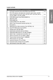
... (10-1 pin COM) 19. LED connector (13-pin LED1_CON1) Page 1-16 1-15 1-17 1-4 1-4 1-8 1-12 1-18 1-11 1-9 1-8 1-14 1-19 1-12 1-13 1-13 1-10 1-20 1-10 1-16 ASUS ROG STRIX X470-F GAMING 1-3 System panel connectors (20-5 pin PANEL) 13. Clear RTC RAM jumper (2-pin CLRTC) 11. DDR4 DIMM slots 6. Addressable RGB header (4-1 pin ADD_HEADER) 14. Q LEDs (DRAM...
... (10-1 pin COM) 19. LED connector (13-pin LED1_CON1) Page 1-16 1-15 1-17 1-4 1-4 1-8 1-12 1-18 1-11 1-9 1-8 1-14 1-19 1-12 1-13 1-13 1-10 1-20 1-10 1-16 ASUS ROG STRIX X470-F GAMING 1-3 System panel connectors (20-5 pin PANEL) 13. Clear RTC RAM jumper (2-pin CLRTC) 11. DDR4 DIMM slots 6. Addressable RGB header (4-1 pin ADD_HEADER) 14. Q LEDs (DRAM...
Users Manual English
Page 19
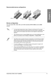
... from the higher-sized channel is the standard way of 512 Mb (64 MB) chips or less (Memory chip capacity counts in Channel A and Channel B. ASUS ROG STRIX X470-F GAMING 1-5 Chapter 1 Recommended memory configurations DIMM_B2* DIMM_B2* DIMM_A2* DIMM_B1 DIMM_B2* DIMM_A1 DIMM_A2* Memory configurations You may install 2 GB, 4 GB, 8 GB, and 16 GB unbuffered DDR4 DIMMs...
... from the higher-sized channel is the standard way of 512 Mb (64 MB) chips or less (Memory chip capacity counts in Channel A and Channel B. ASUS ROG STRIX X470-F GAMING 1-5 Chapter 1 Recommended memory configurations DIMM_B2* DIMM_B2* DIMM_A2* DIMM_B1 DIMM_B2* DIMM_A1 DIMM_A2* Memory configurations You may install 2 GB, 4 GB, 8 GB, and 16 GB unbuffered DDR4 DIMMs...

Users Manual English
Page 21
... running CrossFireX or SLI® mode. • Connect chassis fans to the motherboard chassis fan connectors when using multiple graphics cards for better thermal environment. ASUS ROG STRIX X470-F GAMING 1-7
... running CrossFireX or SLI® mode. • Connect chassis fans to the motherboard chassis fan connectors when using multiple graphics cards for better thermal environment. ASUS ROG STRIX X470-F GAMING 1-7

Users Manual English
Page 23
... help, remove the onboard battery and short the two pins again to re-enter data. Plug the power cord and turn ON the computer. 4. ASUS ROG STRIX X470-F GAMING 1-9 CLRTC PIN 1 ROG STRIX X470-F GAMING Clear RTC RAM To erase the RTC RAM: 1. Hold down the key during the boot process and enter BIOS setup to clear the CMOS...
... help, remove the onboard battery and short the two pins again to re-enter data. Plug the power cord and turn ON the computer. 4. ASUS ROG STRIX X470-F GAMING 1-9 CLRTC PIN 1 ROG STRIX X470-F GAMING Clear RTC RAM To erase the RTC RAM: 1. Hold down the key during the boot process and enter BIOS setup to clear the CMOS...

Users Manual English
Page 25
... GND RSATA_RXN4 RSATA_RXP4 GND SATA6G_1 GND RSATA_TXP1 RSATA_TXN1 GND RSATA_RXN1 RSATA_RXP1 GND SATA6G_2 GND RSATA_TXP2 RSATA_TXN2 GND RSATA_RXN2 RSATA_RXP2 GND ROG STRIX X470-F GAMING Intel® SATA 6 Gb/s connectors • These connectors are set the SATA Mode in the motherboard support ... RAID 0, RAID 1, and RAID 10 configuration through the onboard AMD X470 chipset. AMD Serial ATA 6 Gb/s connectors (7-pin SATA6G_1-6) These connectors connect to section SATA Configuration for details. ASUS ROG STRIX X470-F GAMING 1-11 If you installed Serial ATA hard disk drives, you intend ...
... GND RSATA_RXN4 RSATA_RXP4 GND SATA6G_1 GND RSATA_TXP1 RSATA_TXN1 GND RSATA_RXN1 RSATA_RXP1 GND SATA6G_2 GND RSATA_TXP2 RSATA_TXN2 GND RSATA_RXN2 RSATA_RXP2 GND ROG STRIX X470-F GAMING Intel® SATA 6 Gb/s connectors • These connectors are set the SATA Mode in the motherboard support ... RAID 0, RAID 1, and RAID 10 configuration through the onboard AMD X470 chipset. AMD Serial ATA 6 Gb/s connectors (7-pin SATA6G_1-6) These connectors connect to section SATA Configuration for details. ASUS ROG STRIX X470-F GAMING 1-11 If you installed Serial ATA hard disk drives, you intend ...

Users Manual English
Page 27
... the module to 480 Mb/s connection speed. T_SENSOR GND PIN 1 SENSOR IN ROG STRIX X470-F GAMING T_SENSOR connector ASUS ROG STRIX X470-F GAMING 1-13 Chapter 1 6. USB34 USB12 USB+5V USB_P2USB_P2+ GND NC USB+5V USB_P4USB_P4+ GND NC USB+5V USB_P1USB_P1+ GND USB+5V USB_P3USB_P3+ GND PIN 1 PIN 1 ROG STRIX X470-F GAMING USB2.0 connectors Never connect a 1394 cable to monitor the temperature of the...
... the module to 480 Mb/s connection speed. T_SENSOR GND PIN 1 SENSOR IN ROG STRIX X470-F GAMING T_SENSOR connector ASUS ROG STRIX X470-F GAMING 1-13 Chapter 1 6. USB34 USB12 USB+5V USB_P2USB_P2+ GND NC USB+5V USB_P4USB_P4+ GND NC USB+5V USB_P1USB_P1+ GND USB+5V USB_P3USB_P3+ GND PIN 1 PIN 1 ROG STRIX X470-F GAMING USB2.0 connectors Never connect a 1394 cable to monitor the temperature of the...

Users Manual English
Page 29
...12W 12W 12W 12W 12W 36W Default Speed Q-Fan Controlled Q-Fan Controlled Q-Fan Controlled Q-Fan Controlled Q-Fan Controlled Full Speed Full Speed Shared Control A A B B ASUS ROG STRIX X470-F GAMING 1-15 water pump+, and AIO pump connectors (4-pin CPU_FAN, 4-pin CPU_OPT, 4-pin CHA_FAN1-3; 4-pin W_ PUMP+, 4-pin AIO_PUMP) Connect the fan cables to the ... CHA FAN PWR B AIO PUMP IN CHA FAN IN AIO PUMP PWM CHA FAN PWM C D E G W_PUMP+ GND PUMP PWR PUMP IN PUMP PWM F G ROG STRIX X470-F GAMING Fan connectors • DO NOT forget to connect the fan cables to the fan connectors.
...12W 12W 12W 12W 12W 36W Default Speed Q-Fan Controlled Q-Fan Controlled Q-Fan Controlled Q-Fan Controlled Q-Fan Controlled Full Speed Full Speed Shared Control A A B B ASUS ROG STRIX X470-F GAMING 1-15 water pump+, and AIO pump connectors (4-pin CPU_FAN, 4-pin CPU_OPT, 4-pin CHA_FAN1-3; 4-pin W_ PUMP+, 4-pin AIO_PUMP) Connect the fan cables to the ... CHA FAN PWR B AIO PUMP IN CHA FAN IN AIO PUMP PWM CHA FAN PWM C D E G W_PUMP+ GND PUMP PWR PUMP IN PUMP PWM F G ROG STRIX X470-F GAMING Fan connectors • DO NOT forget to connect the fan cables to the fan connectors.

Users Manual English
Page 31
...If your LED strip does not light up when the system is operating. • The LED strip is detached from the power supply. ASUS ROG STRIX X470-F GAMING 1-17 Chapter 1 12. Before you install or remove any component, ensure that the ATX power supply is switched off or the power... cord is purchased separately. A RGB_HEADER1 B R G +12V PIN 1 B RGB_HEADER2 A PIN 1 +12V G R B B ROG STRIX X470-F GAMING RGB headers The RGB header supports 5050 RGB multi-color LED strips (12V/G/R/B), with the 12V header on the motherboard. • The LED strip will...
...If your LED strip does not light up when the system is operating. • The LED strip is detached from the power supply. ASUS ROG STRIX X470-F GAMING 1-17 Chapter 1 12. Before you install or remove any component, ensure that the ATX power supply is switched off or the power... cord is purchased separately. A RGB_HEADER1 B R G +12V PIN 1 B RGB_HEADER2 A PIN 1 +12V G R B B ROG STRIX X470-F GAMING RGB headers The RGB header supports 5050 RGB multi-color LED strips (12V/G/R/B), with the 12V header on the motherboard. • The LED strip will...

Users Manual English
Page 33
...13. Before you install or remove any component, ensure that the ATX power supply is switched off or the power cord is purchased separately. ROG STRIX X470-F GAMING ADD header The addressable RGB header supports WS2812B addressable RGB LED strips (5V/Data/ Ground), with the 5V header on the motherboard. &#... orientation, and the 5V connector is aligned with a maximum power rating of 3A (5V) and a maximum of 60 LEDs. ASUS ROG STRIX X470-F GAMING 1-19 Addressable RGB header (4-1 pin ADD_HEADER) This connector is for individually addressable RGB WS2812B LED strips or WS2812B based LED strips.
...13. Before you install or remove any component, ensure that the ATX power supply is switched off or the power cord is purchased separately. ROG STRIX X470-F GAMING ADD header The addressable RGB header supports WS2812B addressable RGB LED strips (5V/Data/ Ground), with the 5V header on the motherboard. &#... orientation, and the 5V connector is aligned with a maximum power rating of 3A (5V) and a maximum of 60 LEDs. ASUS ROG STRIX X470-F GAMING 1-19 Addressable RGB header (4-1 pin ADD_HEADER) This connector is for individually addressable RGB WS2812B LED strips or WS2812B based LED strips.

Users Manual English
Page 35
Motherboard installation 1. Chapter 2: Basic Installation Basic Installation 2.1 Building your PC system 2 2.1.1 The diagrams in this section are for all models. The motherboard layout may vary with models, but the installation steps are aligned to the chassis' rear I/O panel. Chapter 2 ASUS ROG STRIX X470-F GAMING 2-1 Place the motherboard into the chassis, ensuring that its rear I/O ports are the same for reference only.
Motherboard installation 1. Chapter 2: Basic Installation Basic Installation 2.1 Building your PC system 2 2.1.1 The diagrams in this section are for all models. The motherboard layout may vary with models, but the installation steps are aligned to the chassis' rear I/O panel. Chapter 2 ASUS ROG STRIX X470-F GAMING 2-1 Place the motherboard into the chassis, ensuring that its rear I/O ports are the same for reference only.

Users Manual English
Page 37
Ensure you use a CPU designed for the AM4 socket. 2.1.2 CPU installation The AMD AM4 socket is compatible with AMD AM4 processors. The CPU fits in only one correct orientation. DO NOT force the CPU into the socket to prevent bending the connectors on the socket and damaging the CPU! 1 2 3 Chapter 2 ASUS ROG STRIX X470-F GAMING 2-3
Ensure you use a CPU designed for the AM4 socket. 2.1.2 CPU installation The AMD AM4 socket is compatible with AMD AM4 processors. The CPU fits in only one correct orientation. DO NOT force the CPU into the socket to prevent bending the connectors on the socket and damaging the CPU! 1 2 3 Chapter 2 ASUS ROG STRIX X470-F GAMING 2-3

Users Manual English
Page 39
Type 2 1 2 3 When using this type of CPU fan, remove the screws and the retention module only. Chapter 2 ASUS ROG STRIX X470-F GAMING 2-5 Do not remove the plate on the bottom.
Type 2 1 2 3 When using this type of CPU fan, remove the screws and the retention module only. Chapter 2 ASUS ROG STRIX X470-F GAMING 2-5 Do not remove the plate on the bottom.

Users Manual English
Page 41
2.1.5 ATX power connection A B OR Ensure to connect the 8-pin power plug. 2.1.6 SATA device connection OR Chapter 2 ASUS ROG STRIX X470-F GAMING 2-7
2.1.5 ATX power connection A B OR Ensure to connect the 8-pin power plug. 2.1.6 SATA device connection OR Chapter 2 ASUS ROG STRIX X470-F GAMING 2-7

Users Manual English
Page 43
2.1.8 Expansion card installation To install PCIe x16 cards To install PCIe x1 cards Chapter 2 ASUS ROG STRIX X470-F GAMING 2-9
2.1.8 Expansion card installation To install PCIe x16 cards To install PCIe x1 cards Chapter 2 ASUS ROG STRIX X470-F GAMING 2-9

Users Manual English
Page 47
... controller. • We strongly recommend that you connect USB 3.1 Gen 2 devices to USB 3.1 Gen 2 ports for faster and better performance from your USB 3.1 Gen 2 devices. ASUS ROG STRIX X470-F GAMING 2-13 PS/2 keyboard/ mouse combo port 2. Audio I /O connection 1 2 3 4 5 3 9 8 3 76 Rear panel connectors 1. Optical S/PDIF OUT port 8.
... controller. • We strongly recommend that you connect USB 3.1 Gen 2 devices to USB 3.1 Gen 2 ports for faster and better performance from your USB 3.1 Gen 2 devices. ASUS ROG STRIX X470-F GAMING 2-13 PS/2 keyboard/ mouse combo port 2. Audio I /O connection 1 2 3 4 5 3 9 8 3 76 Rear panel connectors 1. Optical S/PDIF OUT port 8.

Users Manual English
Page 49
Chapter 2 2.2.2 Audio I/O connections Audio I/O ports Connect to Headphone and Mic Connect to Stereo Speakers Connect to 2-channel Speakers ASUS ROG STRIX X470-F GAMING 2-15
Chapter 2 2.2.2 Audio I/O connections Audio I/O ports Connect to Headphone and Mic Connect to Stereo Speakers Connect to 2-channel Speakers ASUS ROG STRIX X470-F GAMING 2-15

Users Manual English
Page 51
... power, the system power LED on the devices in Chapter 3. 2.4 Turning off . 3. At power on self tests (POST). Follow the instructions in the following order: a. ASUS ROG STRIX X470-F GAMING 2-17 The system then runs the power-on , hold down the key to green after the system LED turns on the screen. If you do...
... power, the system power LED on the devices in Chapter 3. 2.4 Turning off . 3. At power on self tests (POST). Follow the instructions in the following order: a. ASUS ROG STRIX X470-F GAMING 2-17 The system then runs the power-on , hold down the key to green after the system LED turns on the screen. If you do...

Users Manual English
Page 53
...BIOS settings apply to most conditions to instability or boot failure. Chapter 3: BIOS Setup BIOS Setup 3.1 Knowing BIOS 3 The new ASUS UEFI BIOS is a Unified Extensible Interface that complies with UEFI architecture, offering a user-friendly interface that requires further BIOS settings or ...the help of a trained service personnel. When downloading or updating the BIOS file, rename it as your operating system. Chapter 3 ASUS ROG STRIX X470-F GAMING 3-1 The term "BIOS" in the following circumstances: • An error message appears on the screen during the system bootup and...
...BIOS settings apply to most conditions to instability or boot failure. Chapter 3: BIOS Setup BIOS Setup 3.1 Knowing BIOS 3 The new ASUS UEFI BIOS is a Unified Extensible Interface that complies with UEFI architecture, offering a user-friendly interface that requires further BIOS settings or ...the help of a trained service personnel. When downloading or updating the BIOS file, rename it as your operating system. Chapter 3 ASUS ROG STRIX X470-F GAMING 3-1 The term "BIOS" in the following circumstances: • An error message appears on the screen during the system bootup and...

Users Manual English
Page 55
... you enter the BIOS setup program. Refer to EZ Mode Hot Keys Search on the FAQ Displays the CPU temperature, CPU, and memory voltage output ASUS ROG STRIX X470-F GAMING 3-3 The figure below shows an example of the Advanced Mode.
... you enter the BIOS setup program. Refer to EZ Mode Hot Keys Search on the FAQ Displays the CPU temperature, CPU, and memory voltage output ASUS ROG STRIX X470-F GAMING 3-3 The figure below shows an example of the Advanced Mode.


