
RAMPAGE V EDITION 10 Users Manual English
Page 2
... Software This product contains copyrighted software that we would be registered trademarks or copyrights of the product, either (1) for free by downloading it from https://www.asus.com/support/ or (2) for which is distributed without the express written permission of these licenses are used only for backup purposes, without any warranty to infringe. SPECIFICATIONS AND INFORMATION CONTAINED IN THIS MANUAL...
... Software This product contains copyrighted software that we would be registered trademarks or copyrights of the product, either (1) for free by downloading it from https://www.asus.com/support/ or (2) for which is distributed without the express written permission of these licenses are used only for backup purposes, without any warranty to infringe. SPECIFICATIONS AND INFORMATION CONTAINED IN THIS MANUAL...

RAMPAGE V EDITION 10 Users Manual English
Page 5
Contents Chapter 4: RAID Support 4.1 RAID configurations 4-1 4.1.1 RAID definitions 4-1 4.1.2 Installing Serial ATA hard disks 4-2 4.1.3 Intel® Rapid Storage Technology in UEFI BIOS 4-2 4.1.4 Intel® Rapid Storage Technology Option ROM utility 4-6 4.2 Creating a RAID driver disk 4-10 4.2.1 Creating a RAID driver disk in Windows 4-10 Appendix Notices ...A-1 ASUS contact information A-6 v
Contents Chapter 4: RAID Support 4.1 RAID configurations 4-1 4.1.1 RAID definitions 4-1 4.1.2 Installing Serial ATA hard disks 4-2 4.1.3 Intel® Rapid Storage Technology in UEFI BIOS 4-2 4.1.4 Intel® Rapid Storage Technology Option ROM utility 4-6 4.2 Creating a RAID driver disk 4-10 4.2.1 Creating a RAID driver disk in Windows 4-10 Appendix Notices ...A-1 ASUS contact information A-6 v
RAMPAGE V EDITION 10 Users Manual English
Page 7
... supports. Where to find more information Refer to the following parts: 1. Detailed descriptions of the switches, jumpers, and connectors on ASUS hardware and software products. 2. Chapter 1: Product Introduction This chapter describes the features of the standard package. These documents are also provided. 4. Chapter 2: Basic Installation This chapter lists the hardware setup procedures that may have to change system settings through the BIOS Setup menus. Optional...
... supports. Where to find more information Refer to the following parts: 1. Detailed descriptions of the switches, jumpers, and connectors on ASUS hardware and software products. 2. Chapter 1: Product Introduction This chapter describes the features of the standard package. These documents are also provided. 4. Chapter 2: Basic Installation This chapter lists the hardware setup procedures that may have to change system settings through the BIOS Setup menus. Optional...
RAMPAGE V EDITION 10 Users Manual English
Page 9
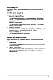
... can only support up to the physical characteristics of these features depends on the next page) ix If a X2 device is subject to 3-Way SLI®/3-Way CrossFireX™. (continued on the CPU types. RAMPAGE V EDITION 10 specifications summary CPU Chipset Memory Expansion Slots Multi-GPU Technology New Intel® Core™ i7 X-Series Processors on LGA 2011-v3 Socket Supports 14nm CPU Supports Intel® Turbo Boost Max Technology 3.0* * The support of...
... can only support up to the physical characteristics of these features depends on the next page) ix If a X2 device is subject to 3-Way SLI®/3-Way CrossFireX™. (continued on the CPU types. RAMPAGE V EDITION 10 specifications summary CPU Chipset Memory Expansion Slots Multi-GPU Technology New Intel® Core™ i7 X-Series Processors on LGA 2011-v3 Socket Supports 14nm CPU Supports Intel® Turbo Boost Max Technology 3.0* * The support of...

RAMPAGE V EDITION 10 Users Manual English
Page 10
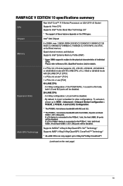
...ports [black] at mid-board share with PCIEX4_1 slot. Intel® I218-V Gigabit LAN- If a X4 or higher device is connected to 1300Mbps transfer speed Bluetooth v4.0 Intel® X99 Chipset - board)** ASMedia® USB 3.1 Controller - RAMPAGE V EDITION 10 specifications summary Storage LAN New Intel® Core™ i7 Processors: - 1 x M.2 PCIe 3.0 x4 Socket 3 with M Key, type 2260/2280/22110 (supports PCIe storage device only)* - 1 x U.2 port (support PCIe 3.0 x4 NVM Express storage)* Intel® X99 Chipset with PCIEX8_4 slot. ** Windows® 10 32-bit does not support RAID...
...ports [black] at mid-board share with PCIEX4_1 slot. Intel® I218-V Gigabit LAN- If a X4 or higher device is connected to 1300Mbps transfer speed Bluetooth v4.0 Intel® X99 Chipset - board)** ASMedia® USB 3.1 Controller - RAMPAGE V EDITION 10 specifications summary Storage LAN New Intel® Core™ i7 Processors: - 1 x M.2 PCIe 3.0 x4 Socket 3 with M Key, type 2260/2280/22110 (supports PCIe storage device only)* - 1 x U.2 port (support PCIe 3.0 x4 NVM Express storage)* Intel® X99 Chipset with PCIEX8_4 slot. ** Windows® 10 32-bit does not support RAID...
RAMPAGE V EDITION 10 Users Manual English
Page 13
...System panel connector 1 x Aura RGB Strip Header 1 x TPM connector 1 x Front panel audio connector (AAFP) 1 x Thunderbolt header 128 Mb Flash ROM, UEFI AMI BIOS, PnP, WfM2.0, SM BIOS 3.0, ACPI 5.0, Multi-language BIOS, ASUS EZ Flash 3, CrashFree BIOS 3, F11 EZ Tuning Wizard, F6 Qfan Control, F3 My Favorites, Quick Note, Last Modified log, F12 PrintScreen, and ASUS DRAM SPD (Serial Presence Detect) memory information. WfM 2.0, WOL by PME, PXE (continued on button 1 x Reset button 1 x Safe Boot button 1 x ReTry button 1 x LN2 mode jumper 1 x Slow mode switch 1 x DRAM channel switch 1 x PCIe...
...System panel connector 1 x Aura RGB Strip Header 1 x TPM connector 1 x Front panel audio connector (AAFP) 1 x Thunderbolt header 128 Mb Flash ROM, UEFI AMI BIOS, PnP, WfM2.0, SM BIOS 3.0, ACPI 5.0, Multi-language BIOS, ASUS EZ Flash 3, CrashFree BIOS 3, F11 EZ Tuning Wizard, F6 Qfan Control, F3 My Favorites, Quick Note, Last Modified log, F12 PrintScreen, and ASUS DRAM SPD (Serial Presence Detect) memory information. WfM 2.0, WOL by PME, PXE (continued on button 1 x Reset button 1 x Safe Boot button 1 x ReTry button 1 x LN2 mode jumper 1 x Slow mode switch 1 x DRAM channel switch 1 x PCIe...

RAMPAGE V EDITION 10 Users Manual English
Page 21
...Power-on (START) button 11. Safe Boot button (SAFE_BOOT) 14. ProbeIt 16. Intel® X99 Serial ATA 6 Gb/s connectors (7-pin SATA6G_1-10) 19. SLI/CFX switch (SLI/CFX) 21. System panel connector (20-3 pin PANEL) 24. ROG Extension connector (18-1 pin ROG_EXT) 27. CPU, CPU optional, high amp, water pump, extension and chassis fan connectors (4-pin CPU_FAN; 4-pin CPU_OPT; 4-pin H_AMP_FAN; 4-pin W_PUMP; 5-pin EXT_FAN; 4-pin CHA_FAN1-3) 7. button (MemOK!) 10. Slow Mode Switch (SLOW_MODE) 12. Thunderbolt header (5-pin TB_HEADER) 25. Q-Code LED (Q_CODE1) 8. MemOK! RESET button...
...Power-on (START) button 11. Safe Boot button (SAFE_BOOT) 14. ProbeIt 16. Intel® X99 Serial ATA 6 Gb/s connectors (7-pin SATA6G_1-10) 19. SLI/CFX switch (SLI/CFX) 21. System panel connector (20-3 pin PANEL) 24. ROG Extension connector (18-1 pin ROG_EXT) 27. CPU, CPU optional, high amp, water pump, extension and chassis fan connectors (4-pin CPU_FAN; 4-pin CPU_OPT; 4-pin H_AMP_FAN; 4-pin W_PUMP; 5-pin EXT_FAN; 4-pin CHA_FAN1-3) 7. button (MemOK!) 10. Slow Mode Switch (SLOW_MODE) 12. Thunderbolt header (5-pin TB_HEADER) 25. Q-Code LED (Q_CODE1) 8. MemOK! RESET button...
RAMPAGE V EDITION 10 Users Manual English
Page 24
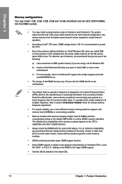
... optimum compatibility, we recommend that the DIMM fan fits to the motherboard. • The default memory operation frequency is dependent on its Serial Presence Detect (SPD), which is recommended to protect the CPU. • Due to Intel® CPU spec, DIMM voltage below 1.65 V is the standard way of the same version or data code (D/C) from a memory module. Any excess memory from the higher-sized channel is...
... optimum compatibility, we recommend that the DIMM fan fits to the motherboard. • The default memory operation frequency is dependent on its Serial Presence Detect (SPD), which is recommended to protect the CPU. • Due to Intel® CPU spec, DIMM voltage below 1.65 V is the standard way of the same version or data code (D/C) from a memory module. Any excess memory from the higher-sized channel is...

RAMPAGE V EDITION 10 Users Manual English
Page 40
... DA DB DC Description Setup Verifying Password Start of Setup Reserved for ASL (see ASL Status Codes section below) Setup Input Wait Reserved for ASL (see ASL Status Codes section below) Ready To Boot event Legacy Boot event Exit Boot Services event Runtime Set Virtual Address MAP Begin Runtime Set Virtual Address MAP End Legacy Option ROM Initialization System Reset USB hot plug PCI bus hot plug Clean-up of NVRAM Configuration Reset (reset of the Architectural Protocols...
... DA DB DC Description Setup Verifying Password Start of Setup Reserved for ASL (see ASL Status Codes section below) Setup Input Wait Reserved for ASL (see ASL Status Codes section below) Ready To Boot event Legacy Boot event Exit Boot Services event Runtime Set Virtual Address MAP Begin Runtime Set Virtual Address MAP End Legacy Option ROM Initialization System Reset USB hot plug PCI bus hot plug Clean-up of NVRAM Configuration Reset (reset of the Architectural Protocols...

RAMPAGE V EDITION 10 Users Manual English
Page 68
... antenna installation Installing the ASUS 3T3R dual band W-Fi antenna Connect the bundled ASUS 3T3R dual band Wi-Fi antenna connector to install the Bluetooth driver before installing the Wi-Fi GO! software. • Ensure that the ASUS 3T3R dual band Wi-Fi antenna is the same for reference only. The illustration above is at the back of the chassis. The I/O port layout may vary with models, but...
... antenna installation Installing the ASUS 3T3R dual band W-Fi antenna Connect the bundled ASUS 3T3R dual band Wi-Fi antenna connector to install the Bluetooth driver before installing the Wi-Fi GO! software. • Ensure that the ASUS 3T3R dual band Wi-Fi antenna is the same for reference only. The illustration above is at the back of the chassis. The I/O port layout may vary with models, but...

RAMPAGE V EDITION 10 Users Manual English
Page 71
... link Off 10 Mbps connection Orange Linked Orange 100 Mbps connection Orange (Blinking) Data activity Green 1 Gbps connection Orange (Blinking Ready to wake up then steady) from S5 mode ACT/LINK SPEED LED LED LAN port You can disable the LAN controllers in BIOS. Some legacy USB devices must update their firmware for your USB 3.0 devices. • Due to the design of the Intel chipset, all USB devices connected to blink even when disabled. ** Audio 2.1, 4.1, 5.1 or 7.1-channel configuration Port Light Blue Lime...
... link Off 10 Mbps connection Orange Linked Orange 100 Mbps connection Orange (Blinking) Data activity Green 1 Gbps connection Orange (Blinking Ready to wake up then steady) from S5 mode ACT/LINK SPEED LED LED LAN port You can disable the LAN controllers in BIOS. Some legacy USB devices must update their firmware for your USB 3.0 devices. • Due to the design of the Intel chipset, all USB devices connected to blink even when disabled. ** Audio 2.1, 4.1, 5.1 or 7.1-channel configuration Port Light Blue Lime...

RAMPAGE V EDITION 10 Users Manual English
Page 79
... section Boot menu for details. To access the Advanced Mode, select Advanced Mode or press the hotkey for entering the BIOS setup program can be changed. Click < or > to the system. ASUS RAMPAGE V EDITION 10 3-3 3.2.1 EZ Mode The EZ Mode provides you an overview of the basic system information, and allows you installed to switch EZ System Tuning modes Displays the CPU/motherboard temperature, Selects the display language Creates storage RAID and CPU voltage output, CPU/chassis/power fan of...
... section Boot menu for details. To access the Advanced Mode, select Advanced Mode or press the hotkey for entering the BIOS setup program can be changed. Click < or > to the system. ASUS RAMPAGE V EDITION 10 3-3 3.2.1 EZ Mode The EZ Mode provides you an overview of the basic system information, and allows you installed to switch EZ System Tuning modes Displays the CPU/motherboard temperature, Selects the display language Creates storage RAID and CPU voltage output, CPU/chassis/power fan of...

RAMPAGE V EDITION 10 Users Manual English
Page 97
...Configuration Chapter 3 ASUS RAMPAGE V EDITION 10 3-21 The AHCI allows the onboard storage driver to enable advanced Serial ATA features that increases storage performance on random workloads by allowing the drive to internally optimize the order of commands. [RAID] Set to [RAID] when you to enable or disable the selected SATA port. Configuration options: [Disabled] [Enabled] Hot Plug These items appear only when the SATA Mode Selection is set the SATA configuration. [Disabled] Disable the SATA function. [IDE] Use SATA hard disk as Parallel ATA storage devices [AHCI] Set to [AHCI...
...Configuration Chapter 3 ASUS RAMPAGE V EDITION 10 3-21 The AHCI allows the onboard storage driver to enable advanced Serial ATA features that increases storage performance on random workloads by allowing the drive to internally optimize the order of commands. [RAID] Set to [RAID] when you to enable or disable the selected SATA port. Configuration options: [Disabled] [Enabled] Hot Plug These items appear only when the SATA Mode Selection is set the SATA configuration. [Disabled] Disable the SATA function. [IDE] Use SATA hard disk as Parallel ATA storage devices [AHCI] Set to [AHCI...

RAMPAGE V EDITION 10 Users Manual English
Page 99
... other BIOS items. Chapter 3 HD Audio Controller [Disabled] HDA will be unconditionally enabled Asmedia USB 3.1 Controller This item allows you to disable or enable the ASMedia USB 3.1 controller. ASUS RAMPAGE V EDITION 10 3-23 Configuration options: [Disabled] [Enabled] RGB LED(onboard) [Disabled] LEDs will not light up. [Enabled] LEDs will be unconditionally disabled [Enabled] HDA will always light up at the S0(Working), S3(Sleep), and S5(Soft off) RGB LED lighting effects This item allows you to set the RGB LED lighting effects to disable or enable...
... other BIOS items. Chapter 3 HD Audio Controller [Disabled] HDA will be unconditionally enabled Asmedia USB 3.1 Controller This item allows you to disable or enable the ASMedia USB 3.1 controller. ASUS RAMPAGE V EDITION 10 3-23 Configuration options: [Disabled] [Enabled] RGB LED(onboard) [Disabled] LEDs will not light up. [Enabled] LEDs will be unconditionally disabled [Enabled] HDA will always light up at the S0(Working), S3(Sleep), and S5(Soft off) RGB LED lighting effects This item allows you to set the RGB LED lighting effects to disable or enable...

RAMPAGE V EDITION 10 Users Manual English
Page 103
Connect the 2-pin connector of the chassis reset button cable to the onboard DRCT header to fully support the Windows® secure update and secure boot. Launch CSM [Auto] [Enabled] [Disabled] The system automatically detects the bootable devices and the addon devices for better compatibility. Configuration options: [UEFI and Legacy OPROM] [Legacy OPROM only] [UEFI only] Boot from unauthorized access and malwares during POST. Configuration options: [Ignore] [Legacy only] [UEFI driver first] Boot from Storage Devices This item allows you to select the type of storage devices that ...
Connect the 2-pin connector of the chassis reset button cable to the onboard DRCT header to fully support the Windows® secure update and secure boot. Launch CSM [Auto] [Enabled] [Disabled] The system automatically detects the bootable devices and the addon devices for better compatibility. Configuration options: [UEFI and Legacy OPROM] [Legacy OPROM only] [UEFI only] Boot from unauthorized access and malwares during POST. Configuration options: [Ignore] [Legacy only] [UEFI driver first] Boot from Storage Devices This item allows you to select the type of storage devices that ...

RAMPAGE V EDITION 10 Users Manual English
Page 104
... to start booting from the available devices. The number of device items that appears on the screen depends on the number of devices installed in the system. • To access Windows® OS in the motherboard for special functions. Configuration options: [Enabled] [Disabled] 3.9.1 GPU Post This item shows the installed graphics cards in the system. It also suggests the configuration of devices installed in the motherboard. Boot Option Priorities These items specify the boot device priority...
... to start booting from the available devices. The number of device items that appears on the screen depends on the number of devices installed in the system. • To access Windows® OS in the motherboard for special functions. Configuration options: [Enabled] [Disabled] 3.9.1 GPU Post This item shows the installed graphics cards in the system. It also suggests the configuration of devices installed in the motherboard. Boot Option Priorities These items specify the boot device priority...

RAMPAGE V EDITION 10 Users Manual English
Page 108
... the instructions in Windows® environment. 2. If there is no problem using a USB flash drive. 3. However, BIOS updating is available in the support USB drive that allows you to boot. ASUS EZ Flash 3: Updates the BIOS using the current version of the available USB devices. 3.11 Updating BIOS The ASUS website publishes the latest BIOS versions to update the motherboard BIOS in Windows® environment. • EZ Update requires an Internet connection either through a network or an ISP (Internet Service Provider). • This utility is...
... the instructions in Windows® environment. 2. If there is no problem using a USB flash drive. 3. However, BIOS updating is available in the support USB drive that allows you to boot. ASUS EZ Flash 3: Updates the BIOS using the current version of the available USB devices. 3.11 Updating BIOS The ASUS website publishes the latest BIOS versions to update the motherboard BIOS in Windows® environment. • EZ Update requires an Internet connection either through a network or an ISP (Internet Service Provider). • This utility is...
RAMPAGE V EDITION 10 Users Manual English
Page 111
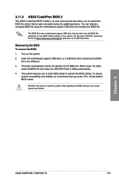
... to enter BIOS Setup to recover the BIOS setting. The utility automatically checks the devices for the BIOS file. When found, the utility reads the BIOS file and enters the ASUS EZ Flash 3 Utility automatically. 4. DO NOT shut down or reset the system while updating the BIOS! Chapter 3 ASUS RAMPAGE V EDITION 10 3-35 Recovering the BIOS To recover the BIOS: 1. Doing so can restore a corrupted BIOS file using the motherboard support USB drive that contains the BIOS file. You can cause system boot failure! The...
... to enter BIOS Setup to recover the BIOS setting. The utility automatically checks the devices for the BIOS file. When found, the utility reads the BIOS file and enters the ASUS EZ Flash 3 Utility automatically. 4. DO NOT shut down or reset the system while updating the BIOS! Chapter 3 ASUS RAMPAGE V EDITION 10 3-35 Recovering the BIOS To recover the BIOS: 1. Doing so can restore a corrupted BIOS file using the motherboard support USB drive that contains the BIOS file. You can cause system boot failure! The...

RAMPAGE V EDITION 10 Users Manual English
Page 114
... to the Boot menu > CSM (Compatibility Support Module) > Launch CSM, then set to Chapter 3 for a RAID configuration: 1. Connect the SATA signal cables. 3. Set the SATA Controller Mode Selection item to [Disabled]. 5. Save your changes and exit the BIOS Setup, then enter the BIOS Setup again. 6. 4.1.2 Installing Serial ATA hard disks The motherboard supports Serial ATA hard disk drives. Chapter 5 4-2 Chapter 5: RAID Support Install the SATA hard disks into the drive bays. 2. Refer to RAID mode, all SATA ports run at RAID mode together. To install the SATA hard disks for...
... to the Boot menu > CSM (Compatibility Support Module) > Launch CSM, then set to Chapter 3 for a RAID configuration: 1. Connect the SATA signal cables. 3. Set the SATA Controller Mode Selection item to [Disabled]. 5. Save your changes and exit the BIOS Setup, then enter the BIOS Setup again. 6. 4.1.2 Installing Serial ATA hard disks The motherboard supports Serial ATA hard disk drives. Chapter 5 4-2 Chapter 5: RAID Support Install the SATA hard disks into the drive bays. 2. Refer to RAID mode, all SATA ports run at RAID mode together. To install the SATA hard disks for...

RAMPAGE V EDITION 10 Users Manual English
Page 122
... press . Click OK. 4. Insert the support USB drive with RAID driver into the USB port, and then click Browse. 3. Exiting the Intel® Rapid Storage Technology Option ROM utility To exit the utility: 1. During the OS installation, click Load Driver to allow you to load the UEFI driver for your optical drive. To set up a Windows® UEFI operating system under RAID mode, ensure to select the installation media containing the RAID driver. 2. The following warning message appears...
... press . Click OK. 4. Insert the support USB drive with RAID driver into the USB port, and then click Browse. 3. Exiting the Intel® Rapid Storage Technology Option ROM utility To exit the utility: 1. During the OS installation, click Load Driver to allow you to load the UEFI driver for your optical drive. To set up a Windows® UEFI operating system under RAID mode, ensure to select the installation media containing the RAID driver. 2. The following warning message appears...


