
User Guide
Page 4
...3.2.1 EZ Mode 3-3 3.2.2 Advanced Mode 3-4 3.3 My Favorites 3-6 3.4 Main menu 3-7 3.5 Extreme Tweaker menu 3-9 3.6 Advanced menu 3-28 3.6.1 CPU Configuration 3-29 3.6.2 PCH Configuration 3-32 3.6.3 PCH Storage Configuration 3-33 3.6.4 System Agent Configuration 3-35 3.6.5 USB Configuration 3-36 3.6.6 Platform Miscellaneous Configuration 3-38 3.6.7 Onboard Devices Configuration 3-39 3.6.8 APM 3-41 ...3.10 Exit menu 3-55 3.11 Updating BIOS 3-56 3.11.1 EZ Update 3-56 3.11.2 ASUS EZ Flash 2 3-57 3.11.3 ASUS CrashFree BIOS 3 3-58 3.11.4 ASUS BIOS Updater 3-59 iv
...3.2.1 EZ Mode 3-3 3.2.2 Advanced Mode 3-4 3.3 My Favorites 3-6 3.4 Main menu 3-7 3.5 Extreme Tweaker menu 3-9 3.6 Advanced menu 3-28 3.6.1 CPU Configuration 3-29 3.6.2 PCH Configuration 3-32 3.6.3 PCH Storage Configuration 3-33 3.6.4 System Agent Configuration 3-35 3.6.5 USB Configuration 3-36 3.6.6 Platform Miscellaneous Configuration 3-38 3.6.7 Onboard Devices Configuration 3-39 3.6.8 APM 3-41 ...3.10 Exit menu 3-55 3.11 Updating BIOS 3-56 3.11.1 EZ Update 3-56 3.11.2 ASUS EZ Flash 2 3-57 3.11.3 ASUS CrashFree BIOS 3 3-58 3.11.4 ASUS BIOS Updater 3-59 iv
User Guide
Page 5
... Streamer 4.6 ROG Audio features Sonic Studio Sonic SenseAmp Sonic SoundStage DTS Connect 4.7 Sonic Radar II 4.8 GameFirst III 4.9 KeyBot 4.10 ASUS Disk Unlocker 4.11 RAMDisk 4.12 MemTweakIt 4.13 ROG CPU-Z 4.14 ROG Connect 4-1 4-1 4-1 4-3 4-4 4-4 4-7 4-7 4-8 4-10 4-11 4-13 4-14 4-17 4-18 4-19 4-21... Dual Intelligent Processors 5 5-Way Optimization Turbo Processing Unit (TPU) Fan Xpert 3 DIGI+ Power Control Turbo App Energy Processing Unit (EPU) USB 3.0 Boost EZ Update System Information USB BIOS Flashback USB Charger+ Push Notice Ai Charger+ Wi-Fi Engine Wi-Fi GO!
... Streamer 4.6 ROG Audio features Sonic Studio Sonic SenseAmp Sonic SoundStage DTS Connect 4.7 Sonic Radar II 4.8 GameFirst III 4.9 KeyBot 4.10 ASUS Disk Unlocker 4.11 RAMDisk 4.12 MemTweakIt 4.13 ROG CPU-Z 4.14 ROG Connect 4-1 4-1 4-1 4-3 4-4 4-4 4-7 4-7 4-8 4-10 4-11 4-13 4-14 4-17 4-18 4-19 4-21... Dual Intelligent Processors 5 5-Way Optimization Turbo Processing Unit (TPU) Fan Xpert 3 DIGI+ Power Control Turbo App Energy Processing Unit (EPU) USB 3.0 Boost EZ Update System Information USB BIOS Flashback USB Charger+ Push Notice Ai Charger+ Wi-Fi Engine Wi-Fi GO!

User Guide
Page 11
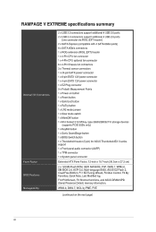
... Connect) 10 x USB 3.0 ports [blue] 1 x Anti-surge LAN (RJ45) port 1 x ASUS Wi-Fi GO! Sonic SenseAmp - supports Asus USB 3.0 Boost: - 4 x USB 3.0 ports ( at mid-board [red])* - 6 x USB 2.0 ports (2 ports at back panel, 4 ports at mid-board)** ASMedia° USB 3.0 controller: -10 x USB 3.0 ports (at ...Connect Intel° X99 Express Chipset - ELNA° Premium audio capacitors - Sonic Studio - RAMPAGE V EXTREME specifications summary Wireless / Bluetooth SupremeFX High Definition Audio USB Back Panel I/O Ports Inter 1218-V Gigabit LAN- Jack-detection, Multi-streaming, and Front Panel ...
... Connect) 10 x USB 3.0 ports [blue] 1 x Anti-surge LAN (RJ45) port 1 x ASUS Wi-Fi GO! Sonic SenseAmp - supports Asus USB 3.0 Boost: - 4 x USB 3.0 ports ( at mid-board [red])* - 6 x USB 2.0 ports (2 ports at back panel, 4 ports at mid-board)** ASMedia° USB 3.0 controller: -10 x USB 3.0 ports (at ...Connect Intel° X99 Express Chipset - ELNA° Premium audio capacitors - Sonic Studio - RAMPAGE V EXTREME specifications summary Wireless / Bluetooth SupremeFX High Definition Audio USB Back Panel I/O Ports Inter 1218-V Gigabit LAN- Jack-detection, Multi-streaming, and Front Panel ...
User Guide
Page 12
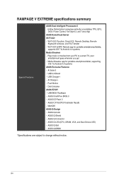
RAMPAGE V EXTREME specifications summary Internal I/O Connectors Form Factor BIOS Features Manageability 2 x USB 3.0 connectors support additional 4 USB 3.0 ports 2 x USB 2.0 connectors support additional 4 USB 2.0 ports [one connector via ROG_EXT header] 2 x SATA Express (compatible with 4 SATA 6Gb/s ports) ... (supports PCIE SSDs only) 1 x KeyBot button 1 x Sonic SoundStage button 1 x BIOS Switch button 1 x Thunderbolt header (5-pin) for ASUS ThunderboldEX II series support 1 x Front panel audio connector (AAFP) 1 x TPM connector 1 x System panel connector Extended ATX Form Factor, 12...
RAMPAGE V EXTREME specifications summary Internal I/O Connectors Form Factor BIOS Features Manageability 2 x USB 3.0 connectors support additional 4 USB 3.0 ports 2 x USB 2.0 connectors support additional 4 USB 2.0 ports [one connector via ROG_EXT header] 2 x SATA Express (compatible with 4 SATA 6Gb/s ports) ... (supports PCIE SSDs only) 1 x KeyBot button 1 x Sonic SoundStage button 1 x BIOS Switch button 1 x Thunderbolt header (5-pin) for ASUS ThunderboldEX II series support 1 x Front panel audio connector (AAFP) 1 x TPM connector 1 x System panel connector Extended ATX Form Factor, 12...
User Guide
Page 14
... app for portable smartphonesltablets, supports iOS 7 & Android 4.0 systems Media Streamer - ASUS C.P.R.(CPU Parameter Recall) - ASUS Q-Shield - ASUS Q-DIMM *Specifications are subject to a smart TV, your PC to change without notice. xiv Al Suite 3 - USB BIOS Flashback - ASUS EZ Flash 2 - ASUS O-Design - ASUS Q-Connector - RAMPAGE V EXTREME specifications summary Special Features ASUS Dual Intelligent Processors 5 - 5-Way Optimization tuning key perfectly consolidates TPU...
... app for portable smartphonesltablets, supports iOS 7 & Android 4.0 systems Media Streamer - ASUS C.P.R.(CPU Parameter Recall) - ASUS Q-Shield - ASUS Q-DIMM *Specifications are subject to a smart TV, your PC to change without notice. xiv Al Suite 3 - USB BIOS Flashback - ASUS EZ Flash 2 - ASUS O-Design - ASUS Q-Connector - RAMPAGE V EXTREME specifications summary Special Features ASUS Dual Intelligent Processors 5 - 5-Way Optimization tuning key perfectly consolidates TPU...
User Guide
Page 19
...supports the LGA2011-v3 socket for faster data retrieval. SATA Express support SATA Express provides faster data transfer speeds of up to eight (8) USB 3.0 ports, fourteen (14) SATA 6 Gb/s ports, and M.2 support for Intel® Goren" i7 processors. It is a .... Total bandwidth for twice the performance of PCIe 2.0 in multi-GPU SLI and CrossFireX solutions to two SATA drives of the SSDs. ASUS RAMPAGE V EXTREME 1-1 IL Product introduction 1.1 Special features U 1.1.1 Product highlights LGA2011-v3 socket for Intel® integrated graphics performance. PCIe 3.0 Ready...
...supports the LGA2011-v3 socket for faster data retrieval. SATA Express support SATA Express provides faster data transfer speeds of up to eight (8) USB 3.0 ports, fourteen (14) SATA 6 Gb/s ports, and M.2 support for Intel® Goren" i7 processors. It is a .... Total bandwidth for twice the performance of PCIe 2.0 in multi-GPU SLI and CrossFireX solutions to two SATA drives of the SSDs. ASUS RAMPAGE V EXTREME 1-1 IL Product introduction 1.1 Special features U 1.1.1 Product highlights LGA2011-v3 socket for Intel® integrated graphics performance. PCIe 3.0 Ready...
User Guide
Page 21
... for important tasks. ROG Connect links your main system to a notebook through a USB cable, allowing you to perform specific or several task at a hardware level. This feature supports USB keyboards only. NOTE: RAMDisk only supports 64-bit operating systems. CPU Level Up...the system memory and turns it can store your motherboard at a hardware level. ASUS RAMPAGE V EXTREME 1-3 With the Dynamic Memory Allocation function, it into actual storage, so you with brand-new current-sensing technology, Extreme Engine Digi+ IV's high-frequency pulse- .0 U width modulation (PWM) ...
... for important tasks. ROG Connect links your main system to a notebook through a USB cable, allowing you to perform specific or several task at a hardware level. This feature supports USB keyboards only. NOTE: RAMDisk only supports 64-bit operating systems. CPU Level Up...the system memory and turns it can store your motherboard at a hardware level. ASUS RAMPAGE V EXTREME 1-3 With the Dynamic Memory Allocation function, it into actual storage, so you with brand-new current-sensing technology, Extreme Engine Digi+ IV's high-frequency pulse- .0 U width modulation (PWM) ...

User Guide
Page 23
ASUS RAMPAGE V EXTREME 1-5 It also allows you to regularly check for your ultimate convenience. 1.1.4 ASUS special features Al Suite 3 CU With its user-friendly interface, ASUS Al Suite 3 consolidates all the exclusive ASUS features into a single software package. It allows you to monitor fan speeds, voltages, and sensor readings. .0 U USB BIOS FlashBack USB BIOS Flashback offers a hassle-free updating...
ASUS RAMPAGE V EXTREME 1-5 It also allows you to regularly check for your ultimate convenience. 1.1.4 ASUS special features Al Suite 3 CU With its user-friendly interface, ASUS Al Suite 3 consolidates all the exclusive ASUS features into a single software package. It allows you to monitor fan speeds, voltages, and sensor readings. .0 U USB BIOS FlashBack USB BIOS Flashback offers a hassle-free updating...
User Guide
Page 27
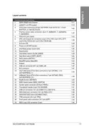
... (KEYBOT) 21 BIOS Switch button (BIOS_SWITCH) 22 System panel connector (20-8 pin PANEL) 23 Thunderbolt header (5-pin TB_HEADER) 24 USB 2.0 connector (10-1 pin USB91112, USB 1314) 25 ROG Extension connector (18-1 pin ROG_EXT) 26 SOUNDSTAGE button (SOUNDSTAGE) 27 TPM connector (20-1 pin TPM) 28 ...34 1-21 1-26 1-24 1-23 1-22 1-45 1-37 1-41 1-35 1-36 1-25 1-23 1-43 1-41 1-38 1-36 1-24 1-40 1-40 1-44 ASUS RAMPAGE V EXTREME 1-9 Layout contents Connectors/Jumpers/Slots 1 DDR4 DIMM slots channel 2 LGA2011-v3 CPU socket 3 ATX power connectors (24-pin EATXPWR; 4-pin EATX12V_1; 8-pin EATX12V_2; 4-...
... (KEYBOT) 21 BIOS Switch button (BIOS_SWITCH) 22 System panel connector (20-8 pin PANEL) 23 Thunderbolt header (5-pin TB_HEADER) 24 USB 2.0 connector (10-1 pin USB91112, USB 1314) 25 ROG Extension connector (18-1 pin ROG_EXT) 26 SOUNDSTAGE button (SOUNDSTAGE) 27 TPM connector (20-1 pin TPM) 28 ...34 1-21 1-26 1-24 1-23 1-22 1-45 1-37 1-41 1-35 1-36 1-25 1-23 1-43 1-41 1-38 1-36 1-24 1-40 1-40 1-44 ASUS RAMPAGE V EXTREME 1-9 Layout contents Connectors/Jumpers/Slots 1 DDR4 DIMM slots channel 2 LGA2011-v3 CPU socket 3 ATX power connectors (24-pin EATXPWR; 4-pin EATX12V_1; 8-pin EATX12V_2; 4-...

User Guide
Page 38
IRQ assignments for this motherboard PCIE_X16_1 PCIE_X8_2 PCIE_x4_1 PCIE_X16/X8_3 PCIE_X8_4 PCIE_X1_1 Intel LAN controller SATA #0 SATA #1 HD Audio EHCI #0 (USB 2.0) EHCI #1 (USB 2.0) XHCI (USB 3.0) A shared shared shared shared shared - shared - - - - - - - - - - - - - - - C shared - - D E F G H - - - - - - - - - - - - - - - - - - - - - - - - - - - - - - - B shared shared shared - shared 1-20 Chapter 1: Product introduction shared - - - shared - - - - - - - - - -
IRQ assignments for this motherboard PCIE_X16_1 PCIE_X8_2 PCIE_x4_1 PCIE_X16/X8_3 PCIE_X8_4 PCIE_X1_1 Intel LAN controller SATA #0 SATA #1 HD Audio EHCI #0 (USB 2.0) EHCI #1 (USB 2.0) XHCI (USB 3.0) A shared shared shared shared shared - shared - - - - - - - - - - - - - - - C shared - - D E F G H - - - - - - - - - - - - - - - - - - - - - - - - - - - - - - - B shared shared shared - shared 1-20 Chapter 1: Product introduction shared - - - shared - - - - - - - - - -
User Guide
Page 43
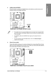
For the location of the KeyBot USB port, refer to the Rear I/O connection section of this user guide. • The KEYBOT_LED near the KEYBOT button lights up if the Keybot ... custom macros and functions stored in the KeyBot microchip. When one without removing the cards. ®Re PCIEX16_SW ANIM • =C E O 0 7 7 E7Jag 4nno!ODEL.J...A__I nrmErcomEmomxg RAMPAGE V EXTREME PCIex16 Lane switch ASUS RAMPAGE V EXTREME 1-25 KeyBot button (KEYBOT) Press this user guide. 9. rciau to :1: El U ®e DECE T u i° AIM NIV417 r'7 O 7 E KEYBOT • ramo===i •...
For the location of the KeyBot USB port, refer to the Rear I/O connection section of this user guide. • The KEYBOT_LED near the KEYBOT button lights up if the Keybot ... custom macros and functions stored in the KeyBot microchip. When one without removing the cards. ®Re PCIEX16_SW ANIM • =C E O 0 7 7 E7Jag 4nno!ODEL.J...A__I nrmErcomEmomxg RAMPAGE V EXTREME PCIex16 Lane switch ASUS RAMPAGE V EXTREME 1-25 KeyBot button (KEYBOT) Press this user guide. 9. rciau to :1: El U ®e DECE T u i° AIM NIV417 r'7 O 7 E KEYBOT • ramo===i •...

User Guide
Page 49
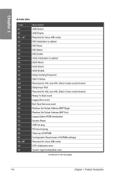
... Plug Controller Initialization PCI Bus Enumeration PCI Bus Request Resources PCI Bus Assign Resources Console Output devices connect Console input devices connect Super 1O Initialization USB initialization is started USB Reset (continued on the next page) ASUS RAMPAGE V EXTREME 1-31 O-Code table Code F9 FA FB -
... Plug Controller Initialization PCI Bus Enumeration PCI Bus Request Resources PCI Bus Assign Resources Console Output devices connect Console input devices connect Super 1O Initialization USB initialization is started USB Reset (continued on the next page) ASUS RAMPAGE V EXTREME 1-31 O-Code table Code F9 FA FB -
User Guide
Page 50
... A5 A6 A7 A8 A9 AA AB AC AD AE AF BO B1 B2 B3 B4 B5 B6 B7 B8- BF DO D1 Description USB Detect USB Enable Reserved for future AMI codes IDE initialization is started IDE Reset IDE Detect IDE Enable SCSI initialization is started SCSI Reset SCSI Detect SCSI... Legacy Boot event Exit Boot Services event Runtime Set Virtual Address MAP Begin Runtime Set Virtual Address MAP End Legacy Option ROM Initialization System Reset USB hot plug PCI bus hot plug Clean-up of NVRAM Configuration Reset (reset of NVRAM settings) Reserved for future AMI codes CPU initialization error System...
... A5 A6 A7 A8 A9 AA AB AC AD AE AF BO B1 B2 B3 B4 B5 B6 B7 B8- BF DO D1 Description USB Detect USB Enable Reserved for future AMI codes IDE initialization is started IDE Reset IDE Detect IDE Enable SCSI initialization is started SCSI Reset SCSI Detect SCSI... Legacy Boot event Exit Boot Services event Runtime Set Virtual Address MAP Begin Runtime Set Virtual Address MAP End Legacy Option ROM Initialization System Reset USB hot plug PCI bus hot plug Clean-up of NVRAM Configuration Reset (reset of NVRAM settings) Reserved for future AMI codes CPU initialization error System...
User Guide
Page 55
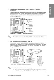
... IN PIN 1 T_SENSOR3 GND PIN 1 SENSOR IN eT_SENSOR1 PIN 1 - GNI) O CND-. .- ASUS RAMPAGE V EXTREME 1-37 IntAJ2_D--. GNI) D+ RAMPAGE V EXTREME USB3.0 connectors 0 USB3_34 g g ..... 2 55 c.) 4 44 4,4 2 II; 4 ' illiiiiii i i i i i i i i i i .., g51dini • The USB 3.0 module is available in your system chassis, with this USB 3.0 connector, you can work with the USB 3.0 specification that you to install the related driver to monitor. The...
... IN PIN 1 T_SENSOR3 GND PIN 1 SENSOR IN eT_SENSOR1 PIN 1 - GNI) O CND-. .- ASUS RAMPAGE V EXTREME 1-37 IntAJ2_D--. GNI) D+ RAMPAGE V EXTREME USB3.0 connectors 0 USB3_34 g g ..... 2 55 c.) 4 44 4,4 2 II; 4 ' illiiiiii i i i i i i i i i i .., g51dini • The USB 3.0 module is available in your system chassis, with this USB 3.0 connector, you can work with the USB 3.0 specification that you to install the related driver to monitor. The...
User Guide
Page 56
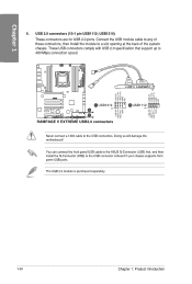
... the system chassis. You can connect the front panel USB cable to the ASUS Q-Connector (USB) first, and then install the Q-Connector (USB) to the USB connectors. Ptg RAMPAGE V EXTREME USB2.0 connectors zo OUSB1112 PIN 1 Never connect a 1394 cable to the USB connector onboard if your chassis supports front panel USB ports. Doing so will damage the motherboard! The...
... the system chassis. You can connect the front panel USB cable to the ASUS Q-Connector (USB) first, and then install the Q-Connector (USB) to the USB connectors. Ptg RAMPAGE V EXTREME USB2.0 connectors zo OUSB1112 PIN 1 Never connect a 1394 cable to the USB connector onboard if your chassis supports front panel USB ports. Doing so will damage the motherboard! The...

User Guide
Page 75
2.1.7 Front I/O Connector Installing the ASUS Q-Connector POWER SW RESET SW HDD LED+ HDD LED 0 LU HDD LED- 0 0 N +CaT, p4R povslER SW a 10 Ground we U Reset Ground Installing the USB 2.0 connector Installing the front panel audio connector USB 2.0 Installing the USB 3.0 connector O USB 3.0 ASUS RAMPAGE V EXTREME AAFP 2-11
2.1.7 Front I/O Connector Installing the ASUS Q-Connector POWER SW RESET SW HDD LED+ HDD LED 0 LU HDD LED- 0 0 N +CaT, p4R povslER SW a 10 Ground we U Reset Ground Installing the USB 2.0 connector Installing the front panel audio connector USB 2.0 Installing the USB 3.0 connector O USB 3.0 ASUS RAMPAGE V EXTREME AAFP 2-11
User Guide
Page 78
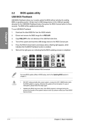
... button for three seconds. Copy R5E.CAP to boot up, please contact your local ASUS Service Center. 2-14 Chapter 2: Basic Installation CD 4. If the BIOS program is completed. In case of the USB flash disk drive. Simply insert a USB storage device to easily update the BIOS without entering the existing BIOS or operating...
... button for three seconds. Copy R5E.CAP to boot up, please contact your local ASUS Service Center. 2-14 Chapter 2: Basic Installation CD 4. If the BIOS program is completed. In case of the USB flash disk drive. Simply insert a USB storage device to easily update the BIOS without entering the existing BIOS or operating...

User Guide
Page 79
... slot is occupied by X4 device, both the SATAEXPRESS_E1, USB3_E910 ports, and the PCIE_X1_1 slot will be disabled. ASUS RAMPAGE V EXTREME 2-15 ROG Connect button 6. Supports ASUS 3.0 Boost Turbo Mode. 9. USB 3.0 ports E9 and El0. The PCIE_X4_1 (gray) slot shares bandwidth with Optical S/PDIF Out port*** **, and... Bluetooth/Wi-Fi module LEDs, LAN port LEDs, and audio port definitions. Intel® LAN (RJ-45) port* 4. USB 3.0 ports El, E2, E3, and E4. Supports ASUS 3.0 Boost Turbo Mode. 8. 2.3 Motherboard rear and audio connections 2.3.1 Rear I /O ports with the PCIE_X1_1 slot, USB3_E910,...
... slot is occupied by X4 device, both the SATAEXPRESS_E1, USB3_E910 ports, and the PCIE_X1_1 slot will be disabled. ASUS RAMPAGE V EXTREME 2-15 ROG Connect button 6. Supports ASUS 3.0 Boost Turbo Mode. 9. USB 3.0 ports E9 and El0. The PCIE_X4_1 (gray) slot shares bandwidth with Optical S/PDIF Out port*** **, and... Bluetooth/Wi-Fi module LEDs, LAN port LEDs, and audio port definitions. Intel® LAN (RJ-45) port* 4. USB 3.0 ports El, E2, E3, and E4. Supports ASUS 3.0 Boost Turbo Mode. 8. 2.3 Motherboard rear and audio connections 2.3.1 Rear I /O ports with the PCIE_X1_1 slot, USB3_E910,...

User Guide
Page 80
... word mark and logos are those of such mark by Bluetooth SIG, Inc. • We strongly recommend that you connect USB 3.0 devices to USB 3.0 ports for faster and better performance for your USB 3.0 devices. • When using the external SATA port, ensure to use of their respective owners. *** Audio 2, 4, 6 or 8-channel configuration Port...
... word mark and logos are those of such mark by Bluetooth SIG, Inc. • We strongly recommend that you connect USB 3.0 devices to USB 3.0 ports for faster and better performance for your USB 3.0 devices. • When using the external SATA port, ensure to use of their respective owners. *** Audio 2, 4, 6 or 8-channel configuration Port...
User Guide
Page 90
... your screen. For more information. Entering BIOS at startup To enter BIOS Setup at startup, press during the Power-On Self Test (POST). Ensure that a USB mouse is enabled in BIOS. • Press the power button to control the BIOS setup program. - The BIOS setup program does not support bluetooth devices...
... your screen. For more information. Entering BIOS at startup To enter BIOS Setup at startup, press during the Power-On Self Test (POST). Ensure that a USB mouse is enabled in BIOS. • Press the power button to control the BIOS setup program. - The BIOS setup program does not support bluetooth devices...


