
User Guide
Page 10
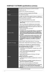
...x SATA Express port (red@bottom, compatible with 2 x SATA 6.0 Gb/s ports) - 1 x M.2 Socket 3 with 28-Lane CPU)* 1 x PCIe 2.0 x16 slot (max. RAMPAGE V EXTREME specifications summary emory Expansion Slots Multi-GPU Technology Storage New Inter Core, i7 Processors on LGA 2011-v3 socket Supports 22nm CPU Supports Intel...DDR4 3300(O.C)*/3000(O.C.)*/2800(O.C)*/ 2666(O.C.)12400(O.C.)12133 MHz, non-ECC, un-buffered memory Quad channel memory architecture Supports Intel® Extreme Memory Profile (XMP) * Hyper DIMM support is occupied by an X1 or X2 device, the SATAEXPRESS_E1 will be disabled....
...x SATA Express port (red@bottom, compatible with 2 x SATA 6.0 Gb/s ports) - 1 x M.2 Socket 3 with 28-Lane CPU)* 1 x PCIe 2.0 x16 slot (max. RAMPAGE V EXTREME specifications summary emory Expansion Slots Multi-GPU Technology Storage New Inter Core, i7 Processors on LGA 2011-v3 socket Supports 22nm CPU Supports Intel...DDR4 3300(O.C)*/3000(O.C.)*/2800(O.C)*/ 2666(O.C.)12400(O.C.)12133 MHz, non-ECC, un-buffered memory Quad channel memory architecture Supports Intel® Extreme Memory Profile (XMP) * Hyper DIMM support is occupied by an X1 or X2 device, the SATAEXPRESS_E1 will be disabled....
User Guide
Page 12
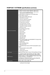
... 1 x M.2 Socket 3 for M Key, type 2260/2280/22110 storage devices (supports PCIE SSDs only) 1 x KeyBot button 1 x Sonic SoundStage button 1 x BIOS Switch button 1 x Thunderbolt header (5-pin) for ASUS ThunderboldEX II series support 1 x Front panel audio connector (AAFP) 1 x TPM connector ...Control, F3 My Favorites, Quick Note, Last Modified log, F12 PrintScreen, F3 Shortcut functions, and ASUS DRAM SPD (Serial Presence Detect) memory information. RAMPAGE V EXTREME specifications summary Internal I/O Connectors Form Factor BIOS Features Manageability 2 x USB 3.0 connectors support additional 4...
... 1 x M.2 Socket 3 for M Key, type 2260/2280/22110 storage devices (supports PCIE SSDs only) 1 x KeyBot button 1 x Sonic SoundStage button 1 x BIOS Switch button 1 x Thunderbolt header (5-pin) for ASUS ThunderboldEX II series support 1 x Front panel audio connector (AAFP) 1 x TPM connector ...Control, F3 My Favorites, Quick Note, Last Modified log, F12 PrintScreen, F3 Shortcut functions, and ASUS DRAM SPD (Serial Presence Detect) memory information. RAMPAGE V EXTREME specifications summary Internal I/O Connectors Form Factor BIOS Features Manageability 2 x USB 3.0 connectors support additional 4...
User Guide
Page 13
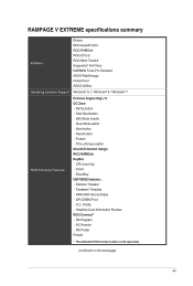
... DirectKey UEFI BIOS features : - Profile - Slow Mode switch - PCIe x16 lane switch DirectCU thermal design ROG RAMDisk KeyBot - O.C. X.M.P. - GPU.DIMM Post - Start button - RAMPAGE V EXTREME specifications summary o are Drivers ROG GameFirst III ROG RAMDisk ROG CPU-Z... ROG Mem TweakIt Kaspersky® Anti-Virus DAEMON Tools Pro Standard ASUS WebStorage HomeCloud ASUS Utilities Operating Systems Support Windows® 8.1 / Windows&#...
... DirectKey UEFI BIOS features : - Profile - Slow Mode switch - PCIe x16 lane switch DirectCU thermal design ROG RAMDisk KeyBot - O.C. X.M.P. - GPU.DIMM Post - Start button - RAMPAGE V EXTREME specifications summary o are Drivers ROG GameFirst III ROG RAMDisk ROG CPU-Z... ROG Mem TweakIt Kaspersky® Anti-Virus DAEMON Tools Pro Standard ASUS WebStorage HomeCloud ASUS Utilities Operating Systems Support Windows® 8.1 / Windows&#...
User Guide
Page 19
... socket for updated details. 3-Way/4-way/Quad-GPU SLITM and CrossFireXTM Support This motherboard features Intel's powerful new X99 platform and optimizes PCIe allocation in the LGA2011-v3 package. ASUS RAMPAGE V EXTREME 1-1 SATA Express support SATA Express provides faster data transfer speeds of the SSDs. It natively supports up with its GPU, dual-channel...
... socket for updated details. 3-Way/4-way/Quad-GPU SLITM and CrossFireXTM Support This motherboard features Intel's powerful new X99 platform and optimizes PCIe allocation in the LGA2011-v3 package. ASUS RAMPAGE V EXTREME 1-1 SATA Express support SATA Express provides faster data transfer speeds of the SSDs. It natively supports up with its GPU, dual-channel...

User Guide
Page 26
fD 1 2 3 ROCASOH/CLSMS • • EATX12,1 31 4 DO OD EATAIAV, 5 6 mataDAD_OPT 7 1 O DDR4 DIMM_D1 (Ube, 288-pin module) LAN _LISIM_EHIO AUDIO CHA_FAN3A 6 29 5 PCIE X8 2 PCIEX4_1 LGA2011-3 OO ROD ROG InteP x99 ■ ■ DC H 15 B061,VICE-LED 6 4 16 17 H H 18 H luITAMIAZ 4 AAASA PCIE_X18/X8_3 Super VG BIOS_LE010 ...
fD 1 2 3 ROCASOH/CLSMS • • EATX12,1 31 4 DO OD EATAIAV, 5 6 mataDAD_OPT 7 1 O DDR4 DIMM_D1 (Ube, 288-pin module) LAN _LISIM_EHIO AUDIO CHA_FAN3A 6 29 5 PCIE X8 2 PCIEX4_1 LGA2011-3 OO ROD ROG InteP x99 ■ ■ DC H 15 B061,VICE-LED 6 4 16 17 H H 18 H luITAMIAZ 4 AAASA PCIE_X18/X8_3 Super VG BIOS_LE010 ...
User Guide
Page 27
...21 1-26 1-24 1-23 1-22 1-45 1-37 1-41 1-35 1-36 1-25 1-23 1-43 1-41 1-38 1-36 1-24 1-40 1-40 1-44 ASUS RAMPAGE V EXTREME 1-9 Layout contents Connectors/Jumpers/Slots 1 DDR4 DIMM slots channel 2 LGA2011-v3 CPU socket 3 ATX power connectors (24-pin EATXPWR; 4-pin EATX12V_1; 8-pin ...EATX12V_2; 4-pin EZ_PLUG) 4 Thermal sensor cable connectors (2-pin T_SENSOR1, T_SENSOR2, T_SENSOR3) 5 PCIe x16 Lane switch 6 CPU and chassis fan connectors (4-pin CPU_FAN; 4-pin CPU_OPT; 4-pin CHA_FAN1A-3A; 4-pin CHA_FAN1B-3B) 7 Q-Code LED 8 Power-...
...21 1-26 1-24 1-23 1-22 1-45 1-37 1-41 1-35 1-36 1-25 1-23 1-43 1-41 1-38 1-36 1-24 1-40 1-40 1-44 ASUS RAMPAGE V EXTREME 1-9 Layout contents Connectors/Jumpers/Slots 1 DDR4 DIMM slots channel 2 LGA2011-v3 CPU socket 3 ATX power connectors (24-pin EATXPWR; 4-pin EATX12V_1; 8-pin ...EATX12V_2; 4-pin EZ_PLUG) 4 Thermal sensor cable connectors (2-pin T_SENSOR1, T_SENSOR2, T_SENSOR3) 5 PCIe x16 Lane switch 6 CPU and chassis fan connectors (4-pin CPU_FAN; 4-pin CPU_OPT; 4-pin CHA_FAN1A-3A; 4-pin CHA_FAN1B-3B) 7 Q-Code LED 8 Power-...

User Guide
Page 36
1.2.5 Expansion slots RD Ensure to do so may cause you physical injury and damage motherboard components. O O PCIE,_X8_2 PCIE,_X4 1 PCIE X16/%8_9 FtpivipRGE V EXTREME PCIE_Xl 1 HRH i PCIEJO 4 ]BeeeeeeZig= Slot No. DO am DO 0 O O 0 PCIE-X16_1 DO 17 DO El DO E DO E D DDD00OO OOOOO00OiEEo ii 0- Failure to unplug the power cord before adding or removing expansion cards. Slot Description 1 PCIe 3.0 x16_1 slot 2 PCIe 3.0 x8_2 slot 3 PCIe 2.0 x4_1 slot 4 PCIe 3.0 x16/8_3 slot 5 PCIe 2.0 x1_1 slot 6 PCIe 3.0 x8_4 slot HEE BEER AMPERE 1-18 Chapter 1: Product introduction
1.2.5 Expansion slots RD Ensure to do so may cause you physical injury and damage motherboard components. O O PCIE,_X8_2 PCIE,_X4 1 PCIE X16/%8_9 FtpivipRGE V EXTREME PCIE_Xl 1 HRH i PCIEJO 4 ]BeeeeeeZig= Slot No. DO am DO 0 O O 0 PCIE-X16_1 DO 17 DO El DO E DO E D DDD00OO OOOOO00OiEEo ii 0- Failure to unplug the power cord before adding or removing expansion cards. Slot Description 1 PCIe 3.0 x16_1 slot 2 PCIe 3.0 x8_2 slot 3 PCIe 2.0 x4_1 slot 4 PCIe 3.0 x16/8_3 slot 5 PCIe 2.0 x1_1 slot 6 PCIe 3.0 x8_4 slot HEE BEER AMPERE 1-18 Chapter 1: Product introduction

User Guide
Page 37
... slot will be disabled. When PCIE_X8_4 is occupied by an X1 or X2 device, the SATAEXPRESS_E1 will be disabled. ASUS RAMPAGE V EXTREME 1-19 U Refer to plug in the 4-pin extra PCIe power supply for stability. When the PCIE_X4_1 slot is occupied, the M.2 will be disabled. • The PCIE_X8_4... will be disabled when using a 28-LANE CPU. • The PCIE_X4_1 (gray) slot shares bandwidth with M.2 x 4. PCIe 3.0 operating mode for 40 lanes CPU Red PCIe slot PCIE_X16_1 PCIE_X8_2 PCIE_X16/X8_3 PCIE_X8_4 Single VGA SLI/CFX x16 3-way SLI/CFX x16 x8 x8 4-way SLI/CFX x16 x8...
... slot will be disabled. When PCIE_X8_4 is occupied by an X1 or X2 device, the SATAEXPRESS_E1 will be disabled. ASUS RAMPAGE V EXTREME 1-19 U Refer to plug in the 4-pin extra PCIe power supply for stability. When the PCIE_X4_1 slot is occupied, the M.2 will be disabled. • The PCIE_X8_4... will be disabled when using a 28-LANE CPU. • The PCIE_X4_1 (gray) slot shares bandwidth with M.2 x 4. PCIe 3.0 operating mode for 40 lanes CPU Red PCIe slot PCIE_X16_1 PCIE_X8_2 PCIE_X16/X8_3 PCIE_X8_4 Single VGA SLI/CFX x16 3-way SLI/CFX x16 x8 x8 4-way SLI/CFX x16 x8...
User Guide
Page 43
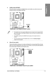
... user guide. 9. When one without removing the cards. ®Re PCIEX16_SW ANIM • =C E O 0 7 7 E7Jag 4nno!ODEL.J...A__I nrmErcomEmomxg RAMPAGE V EXTREME PCIex16 Lane switch ASUS RAMPAGE V EXTREME 1-25 rciau to find out the faulty one of the installed PCIe x16 cards is enabled. • For more information about the KeyBot feature, refer to the Software Support chapter...
... user guide. 9. When one without removing the cards. ®Re PCIEX16_SW ANIM • =C E O 0 7 7 E7Jag 4nno!ODEL.J...A__I nrmErcomEmomxg RAMPAGE V EXTREME PCIex16 Lane switch ASUS RAMPAGE V EXTREME 1-25 rciau to find out the faulty one of the installed PCIe x16 cards is enabled. • For more information about the KeyBot feature, refer to the Software Support chapter...
User Guide
Page 45
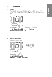
BIOS LED The BIOS LEDs help indicate the BIOS activity. o-lamilottt====rom,oot RAMPAGE V EXTREME PCIex16 LED ASUS RAMPAGE V EXTREME 1-27 Press the BIOS button to switch between BIOS1 and BIOS2 and the LED lights up when the corresponding BIOS is in IQ .0 use. PCIEX16_1_LED1 o PCIEX16_2_LED1 o PCIEX16_3_LED1 o PCIEX16_4_LED1 ion „ O, un. PCIE Lane LED indicator Indicates the PCIE lane used. 1.2.7 Onboard LEDs IL 1. U CI I IsQ EC) LLD:, BIOS_LED1 0 EEO ==70mosommol RAMPAGE V EXTREME BIOS_LED U BIOS_LED2 2.
BIOS LED The BIOS LEDs help indicate the BIOS activity. o-lamilottt====rom,oot RAMPAGE V EXTREME PCIex16 LED ASUS RAMPAGE V EXTREME 1-27 Press the BIOS button to switch between BIOS1 and BIOS2 and the LED lights up when the corresponding BIOS is in IQ .0 use. PCIEX16_1_LED1 o PCIEX16_2_LED1 o PCIEX16_3_LED1 o PCIEX16_4_LED1 ion „ O, un. PCIE Lane LED indicator Indicates the PCIE lane used. 1.2.7 Onboard LEDs IL 1. U CI I IsQ EC) LLD:, BIOS_LED1 0 EEO ==70mosommol RAMPAGE V EXTREME BIOS_LED U BIOS_LED2 2.

User Guide
Page 59
... devices and a CU DisplayPort-enabled display in a daisy-chain configuration. 10. ASUS RAMPAGE V EXTREME 1-41 M.2 connector The M.2 (Socket 3) with M Key supports type 2260 (22 mm x 60 mm), 2280 (22 mm x 80 mm), and 22110 (22 mm x 110 mm) PCIe interface storage devices. 2E M.2(SOCKET3) 11111111111111111 1 IzQ RAMPAGE V EXTREME M.2(SOCKET3) The PCIE_X8_4 slot shares bandwidth with M.2 x4.
... devices and a CU DisplayPort-enabled display in a daisy-chain configuration. 10. ASUS RAMPAGE V EXTREME 1-41 M.2 connector The M.2 (Socket 3) with M Key supports type 2260 (22 mm x 60 mm), 2280 (22 mm x 80 mm), and 22110 (22 mm x 110 mm) PCIe interface storage devices. 2E M.2(SOCKET3) 11111111111111111 1 IzQ RAMPAGE V EXTREME M.2(SOCKET3) The PCIE_X8_4 slot shares bandwidth with M.2 x4.

User Guide
Page 76
2.1.8 Expansion Card installation Installing the PCIe x16 cards sv rt. 0 0 CD 0 0 Installing the PCIe x1 cards 0 2-12 Chapter 2: Basic Installation
2.1.8 Expansion Card installation Installing the PCIe x16 cards sv rt. 0 0 CD 0 0 Installing the PCIe x1 cards 0 2-12 Chapter 2: Basic Installation

User Guide
Page 110
... not remove the thermal module when the manual mode is selected. Gen3 Preset [Auto] Selecting differenct presents can improve the stability of PCIE 3.0/ Configuration options: [Auto] [Presets] [Preset] Preset3 PCIE Clock Amplitude [Auto] Enable this item to adjust the magnitude of the BCLK. Tweaker's Paradise BCLK Amplitude [Auto] This item allows you...
... not remove the thermal module when the manual mode is selected. Gen3 Preset [Auto] Selecting differenct presents can improve the stability of PCIE 3.0/ Configuration options: [Auto] [Presets] [Preset] Preset3 PCIE Clock Amplitude [Auto] Enable this item to adjust the magnitude of the BCLK. Tweaker's Paradise BCLK Amplitude [Auto] This item allows you...

User Guide
Page 114
... external voltage regulator. CPU SVID Support [Auto] Set this item to stop the CPU from 1.20V to the system agent of the processor including its PCIE controller and power control unit (PCU). Configuration options: [Auto] [Disabled] [Enabled] DRAM Voltage (CHA, CHB) / (CHC, CHD) [Auto] This item allows you overclock your system...
... external voltage regulator. CPU SVID Support [Auto] Set this item to stop the CPU from 1.20V to the system agent of the processor including its PCIE controller and power control unit (PCU). Configuration options: [Auto] [Disabled] [Enabled] DRAM Voltage (CHA, CHB) / (CHC, CHD) [Auto] This item allows you overclock your system...

User Guide
Page 123
...speed of the PCIEX16_1 slot. Configuration options: [Enabled] [Disabled] ASUS RAMPAGE V EXTREME 3-35 Advanced mode =::'"18:013O 4Si,0 5, iAktyrmiwtr31 &LIEWCOn.,3, 11K4 Toning Waar.(FIN My Favorites Malin Extreme Tweeter Advanced Monitor Boot Tool AdvarcerINSystemIva Configuration Srstern Ntool Configure°, ConN...item allows you to enable/disable the Intel Virtualization Technology for Directed I /O device assigment to select the operating speed of the PCIe slots. Configuration options: [Enabled] [Disabled] Intel VT for Directed I/O (VT-d) by reporting the I /O (VT-d) [Disabled...
...speed of the PCIEX16_1 slot. Configuration options: [Enabled] [Disabled] ASUS RAMPAGE V EXTREME 3-35 Advanced mode =::'"18:013O 4Si,0 5, iAktyrmiwtr31 &LIEWCOn.,3, 11K4 Toning Waar.(FIN My Favorites Malin Extreme Tweeter Advanced Monitor Boot Tool AdvarcerINSystemIva Configuration Srstern Ntool Configure°, ConN...item allows you to enable/disable the Intel Virtualization Technology for Directed I /O device assigment to select the operating speed of the PCIe slots. Configuration options: [Enabled] [Disabled] Intel VT for Directed I/O (VT-d) by reporting the I /O (VT-d) [Disabled...

User Guide
Page 127
...; USB 3.0 controller of x4 speed. If [M.2] is connected, the M.2 slot will automatically detect the devices connected to select between SATA EXPRESS or PCIE X4. topple,* (C) 20.* Arr*rl*n Solwer•ndix, Er, L*1 Mod fled I enabled SA. Configuration options: [Auto] [M.2] ASMedia USB... My FDVON005 MOM ectl Tweaker Advanced Monitor Boot Tont EXit cglorehorate Monitor AnneeaLa =an Comber,. Configuration options: [Disabled] [Enabled] ASUS RAMPAGE V EXTREME 3-39 mode ll EFII BIOS Utilidy - If an x4 or lower device is chosen, the M.2 slot will be active and...
...; USB 3.0 controller of x4 speed. If [M.2] is connected, the M.2 slot will automatically detect the devices connected to select between SATA EXPRESS or PCIE X4. topple,* (C) 20.* Arr*rl*n Solwer•ndix, Er, L*1 Mod fled I enabled SA. Configuration options: [Auto] [M.2] ASMedia USB... My FDVON005 MOM ectl Tweaker Advanced Monitor Boot Tont EXit cglorehorate Monitor AnneeaLa =an Comber,. Configuration options: [Disabled] [Enabled] ASUS RAMPAGE V EXTREME 3-39 mode ll EFII BIOS Utilidy - If an x4 or lower device is chosen, the M.2 slot will be active and...

User Guide
Page 129
... the OFF state after AC power loss. [Last State] The system goes into either the OFF or ON state, depending on -LAN feature of the PCIE LAN devices. od.oeraMorm CoMigurirtion Er P Ready E'regOne AtPower Lny,s PIWItet On By Pc.l• ENV Power on -LAN feature of the Intel®/Realtek... . Power On By RTC [Disabled] [Disabled] Prevents the RTC from generating a wake event. [Enabled] When set to AC power loss. 3.6.8 APM =f n ' IJEFi BIOS ucn cy - ASUS RAMPAGE V EXTREME 3-41
... the OFF state after AC power loss. [Last State] The system goes into either the OFF or ON state, depending on -LAN feature of the PCIE LAN devices. od.oeraMorm CoMigurirtion Er P Ready E'regOne AtPower Lny,s PIWItet On By Pc.l• ENV Power on -LAN feature of the Intel®/Realtek... . Power On By RTC [Disabled] [Disabled] Prevents the RTC from generating a wake event. [Enabled] When set to AC power loss. 3.6.8 APM =f n ' IJEFi BIOS ucn cy - ASUS RAMPAGE V EXTREME 3-41

User Guide
Page 138
... network devices that you want to launch. Boot from PCI-E/PCI Expansion Devices [Legacy OpROM first] This item allows you to select the type of PCIe/PCI expansion devices that you want to launch. Save Secure Boot Keys This item allows you to launch. Execute the Microsoft® Secure Boot check...
... network devices that you want to launch. Boot from PCI-E/PCI Expansion Devices [Legacy OpROM first] This item allows you to select the type of PCIe/PCI expansion devices that you want to launch. Save Secure Boot Keys This item allows you to launch. Execute the Microsoft® Secure Boot check...

User Guide
Page 211
...before using ROG Connect. • The ROG Connect cable is purchased separately. • ROG Connect must work with ROG Connect Plus to avail full function. PCIE: CPU: ❑PI: DRAM: 26 1331 100.0 122560 1.20000 1.60325 (X) (411-lz) (MHz). 4.14 ROG Connect ROG Connect allows you ... 1.25700 o.r) CRAM 1.60100 (V) EC 1.11100 (V) CH: 1.11100 (V) DPI : 1.16400 (V) CPU PLL qN PCE 1.81200 (5) (V) Fun di an I Refresh My Favonte Seating ASUS RAMPAGE V EXTREME 4-61 Setting up into a stable glow. 3. Ensure that you to activate the function 0 Using RC Tweaklt To use the RC Tweaklt 1.
...before using ROG Connect. • The ROG Connect cable is purchased separately. • ROG Connect must work with ROG Connect Plus to avail full function. PCIE: CPU: ❑PI: DRAM: 26 1331 100.0 122560 1.20000 1.60325 (X) (411-lz) (MHz). 4.14 ROG Connect ROG Connect allows you ... 1.25700 o.r) CRAM 1.60100 (V) EC 1.11100 (V) CH: 1.11100 (V) DPI : 1.16400 (V) CPU PLL qN PCE 1.81200 (5) (V) Fun di an I Refresh My Favonte Seating ASUS RAMPAGE V EXTREME 4-61 Setting up into a stable glow. 3. Ensure that you to activate the function 0 Using RC Tweaklt To use the RC Tweaklt 1.

