User Guide
Page 4
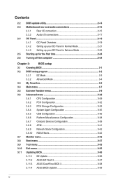
...2-23 2.5 Starting up for the first time 2-24 2.6 Turning off the computer 2-24 Chapter 3: BIOS setup 3.1 Knowing BIOS 3-1 3.2 BIOS setup program 3-2 3.2.1 EZ Mode 3-3 3.2.2 Advanced Mode 3-4 3.3 My Favorites 3-6 3.4 Main menu 3-7 3.5 Extreme Tweaker menu 3-9 3.6 Advanced menu 3-28 3.6.1 CPU Configuration 3-29 3.6.2 PCH Configuration 3-32 3.6.3 PCH ... 3-43 3.8 Boot menu 3-47 3.9 Tool menu 3-53 3.10 Exit menu 3-55 3.11 Updating BIOS 3-56 3.11.1 EZ Update 3-56 3.11.2 ASUS EZ Flash 2 3-57 3.11.3 ASUS CrashFree BIOS 3 3-58 3.11.4 ASUS BIOS Updater 3-59 iv
...2-23 2.5 Starting up for the first time 2-24 2.6 Turning off the computer 2-24 Chapter 3: BIOS setup 3.1 Knowing BIOS 3-1 3.2 BIOS setup program 3-2 3.2.1 EZ Mode 3-3 3.2.2 Advanced Mode 3-4 3.3 My Favorites 3-6 3.4 Main menu 3-7 3.5 Extreme Tweaker menu 3-9 3.6 Advanced menu 3-28 3.6.1 CPU Configuration 3-29 3.6.2 PCH Configuration 3-32 3.6.3 PCH ... 3-43 3.8 Boot menu 3-47 3.9 Tool menu 3-53 3.10 Exit menu 3-55 3.11 Updating BIOS 3-56 3.11.1 EZ Update 3-56 3.11.2 ASUS EZ Flash 2 3-57 3.11.3 ASUS CrashFree BIOS 3 3-58 3.11.4 ASUS BIOS Updater 3-59 iv
User Guide
Page 5
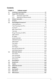
...4-41 Sonic Studio 4-41 Sonic SenseAmp 4-43 Sonic SoundStage 4-45 DTS Connect 4-46 4.7 Sonic Radar II 4-47 4.8 GameFirst III 4-49 4.9 KeyBot...4-52 4.10 ASUS Disk Unlocker 4-54 4.11 RAMDisk...4-55 4.12 MemTweakIt 4-58 4.13 ROG CPU-Z 4-60 4.14 ROG Connect 4-61 v Contents Chapter 4: Software support 4.1 Installing ...10 DIGI+ Power Control 4-11 Turbo App 4-13 Energy Processing Unit (EPU 4-14 USB 3.0 Boost 4-17 EZ Update 4-18 System Information 4-19 USB BIOS Flashback 4-21 USB Charger 4-22 Push Notice 4-23 Ai Charger 4-26 Wi-Fi Engine 4-27 Wi-Fi GO!
...4-41 Sonic Studio 4-41 Sonic SenseAmp 4-43 Sonic SoundStage 4-45 DTS Connect 4-46 4.7 Sonic Radar II 4-47 4.8 GameFirst III 4-49 4.9 KeyBot...4-52 4.10 ASUS Disk Unlocker 4-54 4.11 RAMDisk...4-55 4.12 MemTweakIt 4-58 4.13 ROG CPU-Z 4-60 4.14 ROG Connect 4-61 v Contents Chapter 4: Software support 4.1 Installing ...10 DIGI+ Power Control 4-11 Turbo App 4-13 Energy Processing Unit (EPU 4-14 USB 3.0 Boost 4-17 EZ Update 4-18 System Information 4-19 USB BIOS Flashback 4-21 USB Charger 4-22 Push Notice 4-23 Ai Charger 4-26 Wi-Fi Engine 4-27 Wi-Fi GO!
User Guide
Page 6
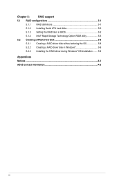
Chapter 5: RAID support 5.1 RAID configurations 5-1 5.1.1 RAID definitions 5-1 5.1.2 Installing Serial ATA hard disks 5-2 5.1.3 Setting the RAID item in BIOS 5-2 5.1.4 Intel® Rapid Storage Technology Option ROM utility 5-3 5.2 Creating a RAID driver disk 5-8 5.2.1 Creating a RAID driver disk without entering the OS 5-8 5.2.2 Creating a RAID driver disk in Windows 5-8 5.2.3 Installing the RAID driver during Windows® OS installation......... 5-9 Appendices Notices ...A-1 ASUS contact information A-5 vi
Chapter 5: RAID support 5.1 RAID configurations 5-1 5.1.1 RAID definitions 5-1 5.1.2 Installing Serial ATA hard disks 5-2 5.1.3 Setting the RAID item in BIOS 5-2 5.1.4 Intel® Rapid Storage Technology Option ROM utility 5-3 5.2 Creating a RAID driver disk 5-8 5.2.1 Creating a RAID driver disk without entering the OS 5-8 5.2.2 Creating a RAID driver disk in Windows 5-8 5.2.3 Installing the RAID driver during Windows® OS installation......... 5-9 Appendices Notices ...A-1 ASUS contact information A-5 vi
User Guide
Page 8
... This chapter describes the features of the standard package. ASUS website The ASUS website (www.asus.com) provides updated information on the motherboard. 2. viii Chapter 3: BIOS setup This chapter explains how to change system settings through the BIOS Setup menus. Optional documentation Your product package may include ...DVD that may have to the following parts: 1. Chapter 4: Software support This chapter describes the contents of the BIOS parameters are not part of the motherboard and the new technology it supports. It includes description of the switches, jumpers, and...
... This chapter describes the features of the standard package. ASUS website The ASUS website (www.asus.com) provides updated information on the motherboard. 2. viii Chapter 3: BIOS setup This chapter explains how to change system settings through the BIOS Setup menus. Optional documentation Your product package may include ...DVD that may have to the following parts: 1. Chapter 4: Software support This chapter describes the contents of the BIOS parameters are not part of the motherboard and the new technology it supports. It includes description of the switches, jumpers, and...
User Guide
Page 12
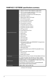
RAMPAGE V EXTREME specifications summary Internal I/O Connectors Form Factor BIOS Features Manageability 2 x USB 3.0 connectors support additional 4 USB 3.0 ports 2 x USB 2.0 connectors support additional 4 USB 2.0 ports [one connector via ROG_EXT header] 2 x SATA Express (compatible with...ATX Form Factor, 12-inch x 10.7-inch (30.5cm x 27.2 cm) 2 x 128 Mb Flash ROM, UEFI AMI BIOS, PnP, DMI2.7, WfM2.0, SM BIOS 2.8, ACPI 5.0, Multi-language BIOS, ASUS EZ Flash 2, CrashFree BIOS 3, F11 EZ Tuning Wizard, F6 Qfan Control, F3 My Favorites, Quick Note, Last Modified log, F12 PrintScreen, F3 Shortcut ...
RAMPAGE V EXTREME specifications summary Internal I/O Connectors Form Factor BIOS Features Manageability 2 x USB 3.0 connectors support additional 4 USB 3.0 ports 2 x USB 2.0 connectors support additional 4 USB 2.0 ports [one connector via ROG_EXT header] 2 x SATA Express (compatible with...ATX Form Factor, 12-inch x 10.7-inch (30.5cm x 27.2 cm) 2 x 128 Mb Flash ROM, UEFI AMI BIOS, PnP, DMI2.7, WfM2.0, SM BIOS 2.8, ACPI 5.0, Multi-language BIOS, ASUS EZ Flash 2, CrashFree BIOS 3, F11 EZ Tuning Wizard, F6 Qfan Control, F3 My Favorites, Quick Note, Last Modified log, F12 PrintScreen, F3 Shortcut ...
User Guide
Page 13
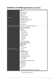
.... (continued on the next page) xiii RAMPAGE V EXTREME specifications summary Software Drivers ROG GameFirst III ROG RAMDisk ROG CPU-Z ROG Mem TweakIt Kaspersky® Anti-Virus DAEMON Tools Pro Standard ASUS WebStorage HomeCloud ASUS Utilities Operating Systems Support Windows® 8.1 ... RAMDisk KeyBot - CPU Level Up - Extreme Tweaker - GPU.DIMM Post - RC Diagram - Reset button - Profile - LN2 Mode header - Tweakers' Paradise - O.C. ROG SSD Secure Erase - Graphics Card Information Preview ROG Connect* - DirectKey UEFI BIOS features : - ReTry button - Safe ...
.... (continued on the next page) xiii RAMPAGE V EXTREME specifications summary Software Drivers ROG GameFirst III ROG RAMDisk ROG CPU-Z ROG Mem TweakIt Kaspersky® Anti-Virus DAEMON Tools Pro Standard ASUS WebStorage HomeCloud ASUS Utilities Operating Systems Support Windows® 8.1 ... RAMDisk KeyBot - CPU Level Up - Extreme Tweaker - GPU.DIMM Post - RC Diagram - Reset button - Profile - LN2 Mode header - Tweakers' Paradise - O.C. ROG SSD Secure Erase - Graphics Card Information Preview ROG Connect* - DirectKey UEFI BIOS features : - ReTry button - Safe ...
User Guide
Page 14
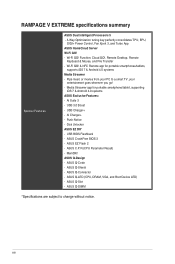
... Unlocker ASUS EZ DIY - ASUS Q-Slot - Push Notice - USB BIOS Flashback - Pipe music or movies from your PC to change without notice. Wi-Fi GO! & NFC Remote app for portable smartphone/tablet, supporting iOS 7 & Android 4.0 systems ASUS Exclusive Features: - AI Suite 3 - ASUS EZ Flash 2 - USB 3.0 Boost - ASUS Q-LED (CPU, DRAM, VGA, and Boot Device LED) - RAMPAGE V EXTREME specifications...
... Unlocker ASUS EZ DIY - ASUS Q-Slot - Push Notice - USB BIOS Flashback - Pipe music or movies from your PC to change without notice. Wi-Fi GO! & NFC Remote app for portable smartphone/tablet, supporting iOS 7 & Android 4.0 systems ASUS Exclusive Features: - AI Suite 3 - ASUS EZ Flash 2 - USB 3.0 Boost - ASUS Q-LED (CPU, DRAM, VGA, and Boot Device LED) - RAMPAGE V EXTREME specifications...
User Guide
Page 21
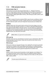
... modulation (PWM) implementation scales to 1 MHz allowing the VRM to achieve a 40% increase in CPU Level UP, XMP, or directly to BIOS. ASUS RAMPAGE V EXTREME 1-3 iROG The iROG is a built-in real-time via a notebook. It greatly improves your junctioned data, RAMDisk features auto data backup and...KeyBot KeyBot is a special IC that provides an instant upgrade to specific keys on -the-fly parameter adjustments at the same time. Rampage V Extreme's exclusive voltage-regulator module (VRM). NOTE: RAMDisk only supports 64-bit operating systems. CPU Level Up With ROG's CPU Level Up...
... modulation (PWM) implementation scales to 1 MHz allowing the VRM to achieve a 40% increase in CPU Level UP, XMP, or directly to BIOS. ASUS RAMPAGE V EXTREME 1-3 iROG The iROG is a built-in real-time via a notebook. It greatly improves your junctioned data, RAMDisk features auto data backup and...KeyBot KeyBot is a special IC that provides an instant upgrade to specific keys on -the-fly parameter adjustments at the same time. Rampage V Extreme's exclusive voltage-regulator module (VRM). NOTE: RAMDisk only supports 64-bit operating systems. CPU Level Up With ROG's CPU Level Up...
User Guide
Page 22
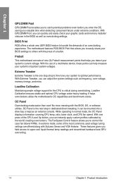
... the use of the most commonly used voltage tuning settings are offered along with the BIOS, OS, or software utilities. With Extreme Tweaker, you can quickly and easily check your system to optimal performance. While operating in the BIOS as well as frequency, over-voltage, memory timings, and more messing with Subzero Sense...
... the use of the most commonly used voltage tuning settings are offered along with the BIOS, OS, or software utilities. With Extreme Tweaker, you can quickly and easily check your system to optimal performance. While operating in the BIOS as well as frequency, over-voltage, memory timings, and more messing with Subzero Sense...
User Guide
Page 23
... offers a hassle-free updating solution for UEFI BIOS updates and download the latest BIOS automatically. Simply install a USB storage device containing the BIOS file, press the BIOS Flashback button for three seconds, and the UEFI BIOS is automatically updated even without entering the existing BIOS or operating system. ASUS RAMPAGE V EXTREME 1-5 Chapter 1 1.1.4 ASUS special features AI Suite 3 With its user...
... offers a hassle-free updating solution for UEFI BIOS updates and download the latest BIOS automatically. Simply install a USB storage device containing the BIOS file, press the BIOS Flashback button for three seconds, and the UEFI BIOS is automatically updated even without entering the existing BIOS or operating system. ASUS RAMPAGE V EXTREME 1-5 Chapter 1 1.1.4 ASUS special features AI Suite 3 With its user...
User Guide
Page 27
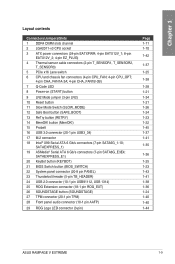
SATAEXPRESS_1) 19 ASMedia® Serial ATA 6 Gb/s connectors (7-pin SATA6G_E3E4; SATAEXPRESS_E1) 20 KeyBot button (KEYBOT) 21 BIOS Switch button (BIOS_SWITCH) 22 System panel connector (20-8 pin PANEL) 23 Thunderbolt header (5-pin TB_HEADER) 24 USB 2.0 connector (10-1 pin USB91112...1-21 1-34 1-21 1-26 1-24 1-23 1-22 1-45 1-37 1-41 1-35 1-36 1-25 1-23 1-43 1-41 1-38 1-36 1-24 1-40 1-40 1-44 ASUS RAMPAGE V EXTREME 1-9 Chapter 1 Layout contents Connectors/Jumpers/Slots 1 DDR4 DIMM slots channel 2 LGA2011-v3 CPU socket 3 ATX power connectors (24-pin EATXPWR; 4-pin EATX12V_1; 8-pin EATX12V_2; 4-...
SATAEXPRESS_1) 19 ASMedia® Serial ATA 6 Gb/s connectors (7-pin SATA6G_E3E4; SATAEXPRESS_E1) 20 KeyBot button (KEYBOT) 21 BIOS Switch button (BIOS_SWITCH) 22 System panel connector (20-8 pin PANEL) 23 Thunderbolt header (5-pin TB_HEADER) 24 USB 2.0 connector (10-1 pin USB91112...1-21 1-34 1-21 1-26 1-24 1-23 1-22 1-45 1-37 1-41 1-35 1-36 1-25 1-23 1-43 1-41 1-38 1-36 1-24 1-40 1-40 1-44 ASUS RAMPAGE V EXTREME 1-9 Chapter 1 Layout contents Connectors/Jumpers/Slots 1 DDR4 DIMM slots channel 2 LGA2011-v3 CPU socket 3 ATX power connectors (24-pin EATXPWR; 4-pin EATX12V_1; 8-pin EATX12V_2; 4-...
User Guide
Page 35
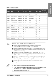
...inserted into four red slots and two black slots as two pairs of quad-channel memory configuration. settings in the BIOS for the hyper DIMM support. • Visit the ASUS website for better compatibility. Size SS/ DS F4-2133C12Q-16GRR 16GB(4GB*4) SS F4-2133C12Q-32GRR 32GB(8GB*4) ... provides hyper DIMM support function. • Hyper DIMM support is subject to the physical characteristics of dualchannel memory configuration. ASUS RAMPAGE V EXTREME 1-17 Double-sided DIMM support: Supports one (1) module inserted into all slots as one pair of individual CPUs. Chapter 1 DDR4 2133 MHz...
...inserted into four red slots and two black slots as two pairs of quad-channel memory configuration. settings in the BIOS for the hyper DIMM support. • Visit the ASUS website for better compatibility. Size SS/ DS F4-2133C12Q-16GRR 16GB(4GB*4) SS F4-2133C12Q-32GRR 32GB(8GB*4) ... provides hyper DIMM support function. • Hyper DIMM support is subject to the physical characteristics of dualchannel memory configuration. ASUS RAMPAGE V EXTREME 1-17 Double-sided DIMM support: Supports one (1) module inserted into all slots as one pair of individual CPUs. Chapter 1 DDR4 2133 MHz...
User Guide
Page 40
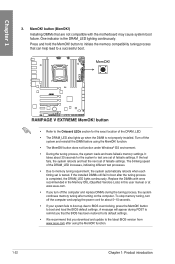
To stop memory tuning, turn off the computer and replace DIMMs during POST to remind you that the BIOS has been restored to the latest BIOS version from www.asus.com after the tuning process is the DRAM_LED lighting continuously. function. • The MemOK! button does not function ... after using the MemOK! If the test fails, the system reboots and test the next set is not properly installed. button to BIOS overclocking, press the MemOK! One indicator is completed, the DRAM_LED lights continuously. If the installed DIMMs still fail to memory tuning requirement...
To stop memory tuning, turn off the computer and replace DIMMs during POST to remind you that the BIOS has been restored to the latest BIOS version from www.asus.com after the tuning process is the DRAM_LED lighting continuously. function. • The MemOK! button does not function ... after using the MemOK! If the test fails, the system reboots and test the next set is not properly installed. button to BIOS overclocking, press the MemOK! One indicator is completed, the DRAM_LED lights continuously. If the installed DIMMs still fail to memory tuning requirement...
User Guide
Page 41
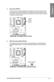
ASUS RAMPAGE V EXTREME 1-23 ReTry button (RETRY) The ReTry button is specially designed for overclockers and is most useful during the booting process where the Reset button is rendered useless. Press the BIOS button to achieve a successful POST. 5. BIOS Switch button (BIOS_SWITCH) The motherboard comes with two BIOS. The nearby BIOS LEDs indicate the currently selected BIOS. Chapter 1 4. When pressed, it forces the system to reboot while retaining the same settings to be retried in quick succession to switch BIOS and load different BIOS settings.
ASUS RAMPAGE V EXTREME 1-23 ReTry button (RETRY) The ReTry button is specially designed for overclockers and is most useful during the booting process where the Reset button is rendered useless. Press the BIOS button to achieve a successful POST. 5. BIOS Switch button (BIOS_SWITCH) The motherboard comes with two BIOS. The nearby BIOS LEDs indicate the currently selected BIOS. Chapter 1 4. When pressed, it forces the system to reboot while retaining the same settings to be retried in quick succession to switch BIOS and load different BIOS settings.
User Guide
Page 42
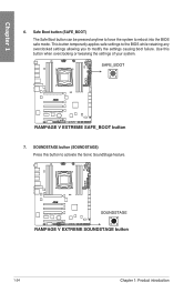
Use this button to activate the Sonic SoundStage feature. 1-24 Chapter 1: Product introduction Safe Boot button (SAFE_BOOT) The Safe Boot button can be pressed anytime to force the system to modify the settings causing boot failure. SOUNDSTAGE button (SOUNDSTAGE) Press this button when overclocking or tweaking the settings of your system. 7. This button temporarily applies safe settings to the BIOS while retaining any overclocked settings allowing you to reboot into the BIOS safe mode. Chapter 1 6.
Use this button to activate the Sonic SoundStage feature. 1-24 Chapter 1: Product introduction Safe Boot button (SAFE_BOOT) The Safe Boot button can be pressed anytime to force the system to modify the settings causing boot failure. SOUNDSTAGE button (SOUNDSTAGE) Press this button when overclocking or tweaking the settings of your system. 7. This button temporarily applies safe settings to the BIOS while retaining any overclocked settings allowing you to reboot into the BIOS safe mode. Chapter 1 6.
User Guide
Page 45
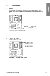
Chapter 1 1.2.7 Onboard LEDs 1. Press the BIOS button to switch between BIOS1 and BIOS2 and the LED lights up when the corresponding BIOS is in use. 2. ASUS RAMPAGE V EXTREME 1-27 PCIE Lane LED indicator Indicates the PCIE lane used. BIOS LED The BIOS LEDs help indicate the BIOS activity.
Chapter 1 1.2.7 Onboard LEDs 1. Press the BIOS button to switch between BIOS1 and BIOS2 and the LED lights up when the corresponding BIOS is in use. 2. ASUS RAMPAGE V EXTREME 1-27 PCIE Lane LED indicator Indicates the PCIE lane used. BIOS LED The BIOS LEDs help indicate the BIOS activity.

User Guide
Page 53
SATAEXPRESS_1) These connectors connect to the RAID configurations section or the manual bundled in the BIOS to [AHCI Mode] by default. If you installed Serial ATA hard disk drives, you intend to create a Serial ATA RAID array using these connectors,...chipset. • These connectors are set the SATA Mode item in the motherboard support DVD. Intel® X99 Serial ATA 6 Gb/s connectors (7-pin SATA6G_1-10; ASUS RAMPAGE V EXTREME 1-35 Refer to the PCH Storage Configuration section for details. • Before creating a RAID array, refer to Serial ATA 6 Gb/s hard disk drives via ...
SATAEXPRESS_1) These connectors connect to the RAID configurations section or the manual bundled in the BIOS to [AHCI Mode] by default. If you installed Serial ATA hard disk drives, you intend to create a Serial ATA RAID array using these connectors,...chipset. • These connectors are set the SATA Mode item in the motherboard support DVD. Intel® X99 Serial ATA 6 Gb/s connectors (7-pin SATA6G_1-10; ASUS RAMPAGE V EXTREME 1-35 Refer to the PCH Storage Configuration section for details. • Before creating a RAID array, refer to Serial ATA 6 Gb/s hard disk drives via ...
User Guide
Page 55
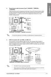
ASUS RAMPAGE V EXTREME 1-37 The optional fans 1, 2, and 3 can have a front panel USB 3.0 solution. • The USB ...chassis, with this USB 3.0 connector, you to install the related driver to monitor. To monitor the temperature at the BIOS, go to 4.8Gbps connection speed. If the USB 3.0 front panel cable is for the additional USB 3.0 ports,...T_SENSOR1, T_SENSOR2, T_SENSOR3) These connectors are based on the devices that supports up to BIOS>Monitor>Temperature Monitor. 5. Connect the thermal sensor cables to these connectors and place the other end on xHCI specification. Chapter...
ASUS RAMPAGE V EXTREME 1-37 The optional fans 1, 2, and 3 can have a front panel USB 3.0 solution. • The USB ...chassis, with this USB 3.0 connector, you to install the related driver to monitor. To monitor the temperature at the BIOS, go to 4.8Gbps connection speed. If the USB 3.0 front panel cable is for the additional USB 3.0 ports,...T_SENSOR1, T_SENSOR2, T_SENSOR3) These connectors are based on the devices that supports up to BIOS>Monitor>Temperature Monitor. 5. Connect the thermal sensor cables to these connectors and place the other end on xHCI specification. Chapter...
User Guide
Page 58
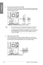
... audio capability. • If you want to connect a high-definition front panel audio module to this connector, set the Front Panel Type item in the BIOS setup to [AC97].
... audio capability. • If you want to connect a high-definition front panel audio module to this connector, set the Front Panel Type item in the BIOS setup to [AC97].
User Guide
Page 61
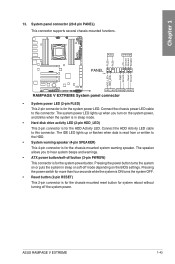
.... • Hard disk drive activity LED (2-pin HDD_LED) This 2-pin connector is for system reboot without turning off the system power. ASUS RAMPAGE V EXTREME 1-43 Connect the chassis power LED cable to the HDD. • System warning speaker (4-pin SPEAKER) This 4-pin connector is for ...system OFF. • Reset button (2-pin RESET) This 2-pin connector is for the system power button. The speaker allows you turn on the BIOS settings. Chapter 1 13. System panel connector (20-8 pin PANEL) This connector supports several chassis-mounted functions. • System power LED (2-...
.... • Hard disk drive activity LED (2-pin HDD_LED) This 2-pin connector is for system reboot without turning off the system power. ASUS RAMPAGE V EXTREME 1-43 Connect the chassis power LED cable to the HDD. • System warning speaker (4-pin SPEAKER) This 4-pin connector is for ...system OFF. • Reset button (2-pin RESET) This 2-pin connector is for the system power button. The speaker allows you turn on the BIOS settings. Chapter 1 13. System panel connector (20-8 pin PANEL) This connector supports several chassis-mounted functions. • System power LED (2-...


