
User Manual
Page 6
... 4-3 4.2.4 Make disk menu 4-4 4.2.5 Manual menu 4-4 4.2.6 Video menu 4-5 4.2.7 ASUS Contact information 4-5 4.2.8 Other information 4-6 4.2.2 Obtaining the software manuals 4-8 4.3 Software information 4-9 vi Contents 3.5.4 USB Configuration 3-28 3.5.5 PCIPnP 3-29 3.5.6 LED Control 3-30 3.5.7 iROG Configuration 3-31 3.5.8 ROG Connect 3-32 3.6 Power menu 3-...3-34 3.6.5 EuP Ready [Disabled 3-34 3.6.7 Hardware Monitor 3-36 3.7 Boot menu 3-39 3.7.1 Boot Device Priority 3-39 3.7.2 Boot Settings Configuration 3-40 3.7.3 Security 3-41 3.8 Tools menu 3-43 3.8.1 ASUS EZ Flash 2 3-43...
... 4-3 4.2.4 Make disk menu 4-4 4.2.5 Manual menu 4-4 4.2.6 Video menu 4-5 4.2.7 ASUS Contact information 4-5 4.2.8 Other information 4-6 4.2.2 Obtaining the software manuals 4-8 4.3 Software information 4-9 vi Contents 3.5.4 USB Configuration 3-28 3.5.5 PCIPnP 3-29 3.5.6 LED Control 3-30 3.5.7 iROG Configuration 3-31 3.5.8 ROG Connect 3-32 3.6 Power menu 3-...3-34 3.6.5 EuP Ready [Disabled 3-34 3.6.7 Hardware Monitor 3-36 3.7 Boot menu 3-39 3.7.1 Boot Device Priority 3-39 3.7.2 Boot Settings Configuration 3-40 3.7.3 Security 3-41 3.8 Tools menu 3-43 3.8.1 ASUS EZ Flash 2 3-43...
User Manual
Page 17
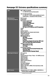
...;y ProbeIt iROG Extreme Tweaker BIOS Flashback with onboard switch button USB BIOS Flashback Loadline Calibration ROG Extreme OC kit -...Rampage III Extreme specifications summary USB ROG Exclusive Overclocking Features Other Special Features BIOS Features NEC® USB 3.0 controller - 2 x USB 3.0/2.0 ports (at back panel) Intel® ICH10R Southbridge - 9 x USB 2.0/1.1 ports (2 ports at midboard; 6 ports at rear) ASUS MyLogo3 ASUS Fan Xpert ASUS EZ Flash 2 ASUS CrashFree BIOS 3 Q-Fan Plus ROG BIOS Wallpaper ASUS Q-Connector ASUS Q-LED (CPU, DRAM, VGA, Boot Device LED) ASUS Q-Slot ASUS...
...;y ProbeIt iROG Extreme Tweaker BIOS Flashback with onboard switch button USB BIOS Flashback Loadline Calibration ROG Extreme OC kit -...Rampage III Extreme specifications summary USB ROG Exclusive Overclocking Features Other Special Features BIOS Features NEC® USB 3.0 controller - 2 x USB 3.0/2.0 ports (at back panel) Intel® ICH10R Southbridge - 9 x USB 2.0/1.1 ports (2 ports at midboard; 6 ports at rear) ASUS MyLogo3 ASUS Fan Xpert ASUS EZ Flash 2 ASUS CrashFree BIOS 3 Q-Fan Plus ROG BIOS Wallpaper ASUS Q-Connector ASUS Q-LED (CPU, DRAM, VGA, Boot Device LED) ASUS Q-Slot ASUS...

User Manual
Page 35
Q LED Q LEDs check key components (CPU, DRAM, VGA card, and booting devices) in any motherboard component. This user-friendly design provides an intuitional way to boot. The illustration below shows the location of the onboard power-on switch that lights up to indicate that .... 7. ROG Rampage III Extreme 2-5 This is a reminder that you should shut down the system and unplug the power cable before you turn on switch. Power LED The motherboard comes with a power-on switch. Wait till the flash stops before removing or plugging in sequence during motherboard booting process.
Q LED Q LEDs check key components (CPU, DRAM, VGA card, and booting devices) in any motherboard component. This user-friendly design provides an intuitional way to boot. The illustration below shows the location of the onboard power-on switch that lights up to indicate that .... 7. ROG Rampage III Extreme 2-5 This is a reminder that you should shut down the system and unplug the power cable before you turn on switch. Power LED The motherboard comes with a power-on switch. Wait till the flash stops before removing or plugging in sequence during motherboard booting process.

User Manual
Page 83
... then a pause (repeated) One continuous beep followed by three short beeps One continuous beep followed by four short beeps Description VGA detected Quick boot set to enter the BIOS Setup. Connect the power cord to the power connector at the back of the system chassis. 4. After applying ...runs the power-on the system front panel case lights up or switch between orange and green after the system LED turns on the screen. At power on the devices in Chapter 3. ROG Rampage III Extreme 2-53 Connect the power cord to a power outlet that all the connections, replace the system case cover. 2....
... then a pause (repeated) One continuous beep followed by three short beeps One continuous beep followed by four short beeps Description VGA detected Quick boot set to enter the BIOS Setup. Connect the power cord to the power connector at the back of the system chassis. 4. After applying ...runs the power-on the system front panel case lights up or switch between orange and green after the system LED turns on the screen. At power on the devices in Chapter 3. ROG Rampage III Extreme 2-53 Connect the power cord to a power outlet that all the connections, replace the system case cover. 2....

User Manual
Page 108
... may be different due to the CPU you to change the settings for the CPU and other system devices. Rampage III Extreme BIOS SETUP Advanced Configure advanced CPU settings Module Version:01.04 Manufacturer:Intel Brand String:Intel(R) Core(TM... show the CPU-related information that the BIOS automatically detects. Rampage III Extreme BIOS SETUP Version 0261 Extreme Tweaker Main Advanced Power Boot Tools Exit CPU Configuration Chipset Onboard Devices Configuration USB Configuration LED Control iROG Configuration ROG Connect Configure CPU. ←→ ...
... may be different due to the CPU you to change the settings for the CPU and other system devices. Rampage III Extreme BIOS SETUP Advanced Configure advanced CPU settings Module Version:01.04 Manufacturer:Intel Brand String:Intel(R) Core(TM... show the CPU-related information that the BIOS automatically detects. Rampage III Extreme BIOS SETUP Version 0261 Extreme Tweaker Main Advanced Power Boot Tools Exit CPU Configuration Chipset Onboard Devices Configuration USB Configuration LED Control iROG Configuration ROG Connect Configure CPU. ←→ ...

User Manual
Page 187
... century to text mode 4. Switch screen back to 20h or 19h 4. Initialize device option ROMs. 1. Build MP table 2. Build & update ESCD 3. Boot attempt (INT 19h) ROG Rampage III Extreme A-3 Initialize PnP boot devices 1. Set up ACPI table at top of IRQs. Assign IRQs to PCI devices 7. Load CMOS time into DOS timer tick 5. USB final Initialization 2. Build ...NUM LOCK UPDT DMI INT 19H Description Clear EPA or customization logo. 1. Invoke ISA adapter ROMs 6. Initialize APM 8. Call chipset power management hook. 2. Update keyboard LED & typematic rate 1.
... century to text mode 4. Switch screen back to 20h or 19h 4. Initialize device option ROMs. 1. Build MP table 2. Build & update ESCD 3. Boot attempt (INT 19h) ROG Rampage III Extreme A-3 Initialize PnP boot devices 1. Set up ACPI table at top of IRQs. Assign IRQs to PCI devices 7. Load CMOS time into DOS timer tick 5. USB final Initialization 2. Build ...NUM LOCK UPDT DMI INT 19H Description Clear EPA or customization logo. 1. Invoke ISA adapter ROMs 6. Initialize APM 8. Call chipset power management hook. 2. Update keyboard LED & typematic rate 1.


