User Manual
Page 25
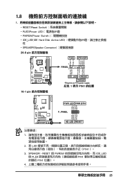
PWR Ground Reset Ground 10-1 pin IDE_LED RESET PWRSW * Requires an ATX power supply. 紅色 1 表示 PIN1 的位置 PLED+ PLEDPWR GND IDELED+ IDELED- Ground Reset PWR LED PWR BTN M2N-X F_PANEL HD LED ...
PWR Ground Reset Ground 10-1 pin IDE_LED RESET PWRSW * Requires an ATX power supply. 紅色 1 表示 PIN1 的位置 PLED+ PLEDPWR GND IDELED+ IDELED- Ground Reset PWR LED PWR BTN M2N-X F_PANEL HD LED ...
User Manual
Page 26
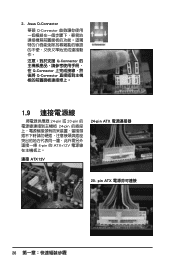
Asus Q-Connector 華碩 Q-Connector Q-Connector Q-Connector Q-Connector 1.9 24-pin 或 20-pin 24-pin 4-pin 的 ATX+12V 連接 ATX12V 24-pin ATX 20- pin ATX 26 2.
Asus Q-Connector 華碩 Q-Connector Q-Connector Q-Connector Q-Connector 1.9 24-pin 或 20-pin 24-pin 4-pin 的 ATX+12V 連接 ATX12V 24-pin ATX 20- pin ATX 26 2.

User Manual
Page 12
... Recall) LCD Poster Onboard Switches: Power / Reset / Clr CMOS (at rear panel) ASUS Q-Connector ASUS Q-Fan 2 ASUS EZ Flash 2 ASUS CrashFree BIOS 3 ASUS MyLogo 3™ 1 x PS/2 Keyboard (purple) 1 x S/PDIF Out (Coaxial + Optical) 1 x IEEE1394a port 2 x LAN (RJ45) ports 6 x USB 2.0/1.1 ports 1... 24-pin ATX Power connector 8-pin ATX 12V Power connector 1 x En/Dis-able Clr CMOS 1 x LCD Poster connector 1 x System panel connector 1 x Power-on switch 1 x Reset switch (continued on the next page) xii ASUS EPU (Energy Processing Unit) - Voltiminder LED - Rampage Formula specifications summary ROG...
... Recall) LCD Poster Onboard Switches: Power / Reset / Clr CMOS (at rear panel) ASUS Q-Connector ASUS Q-Fan 2 ASUS EZ Flash 2 ASUS CrashFree BIOS 3 ASUS MyLogo 3™ 1 x PS/2 Keyboard (purple) 1 x S/PDIF Out (Coaxial + Optical) 1 x IEEE1394a port 2 x LAN (RJ45) ports 6 x USB 2.0/1.1 ports 1... 24-pin ATX Power connector 8-pin ATX 12V Power connector 1 x En/Dis-able Clr CMOS 1 x LCD Poster connector 1 x System panel connector 1 x Power-on switch 1 x Reset switch (continued on the next page) xii ASUS EPU (Energy Processing Unit) - Voltiminder LED - Rampage Formula specifications summary ROG...

User Manual
Page 13
xiii Support DVD: Drivers ASUS PC Probe II ASUS Update ASUS AI Suite Futuremark® 3DMark® 06 Advanced Edition Kaspersky® Anti-virus software ATX Form Factor, 12"x 9.6" (30.5 cm x 24.4 cm) *Specifications are subject to change without notice. Rampage Formula specifications summary BIOS Features Manageability ...65533;�B�I�O�S� WOL by PME, WOR by PME, Chassis Intrusion, PXE LCD Poster ASUS Optional Fan SupremeFX II Audio Card 3 in 1 ASUS Q-connector kit UltraDMA 133/100/66 cable Floppy disk drive cable Serial ATA cables Serial ATA power cables...
xiii Support DVD: Drivers ASUS PC Probe II ASUS Update ASUS AI Suite Futuremark® 3DMark® 06 Advanced Edition Kaspersky® Anti-virus software ATX Form Factor, 12"x 9.6" (30.5 cm x 24.4 cm) *Specifications are subject to change without notice. Rampage Formula specifications summary BIOS Features Manageability ...65533;�B�I�O�S� WOL by PME, WOR by PME, Chassis Intrusion, PXE LCD Poster ASUS Optional Fan SupremeFX II Audio Card 3 in 1 ASUS Q-connector kit UltraDMA 133/100/66 cable Floppy disk drive cable Serial ATA cables Serial ATA power cables...
User Manual
Page 27
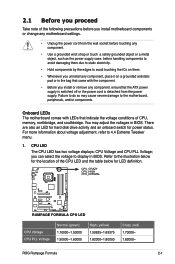
...remove any component, ensurethat the ATX power supply is switched off or the power cord is detached from the power supply. 2.1 Before you proceed Take note of the following precautions before you install motherboard components or change any motherboard settings. • Unplug the ...10000~1.50000 1.50000~1.60000 High (yellow) 1.50625~1.69375 1.62000~1.80000 Crazy (red) 1.70000~ 1.82000~ ROG Rampage Formula 2-1 For more information about voltage adjustment, refer to the motherboard, peripherals, and/or components. Failure to do so may adjust the voltages in BIOS. You may cause severe ...
...remove any component, ensurethat the ATX power supply is switched off or the power cord is detached from the power supply. 2.1 Before you proceed Take note of the following precautions before you install motherboard components or change any motherboard settings. • Unplug the ...10000~1.50000 1.50000~1.60000 High (yellow) 1.50625~1.69375 1.62000~1.80000 Crazy (red) 1.70000~ 1.82000~ ROG Rampage Formula 2-1 For more information about voltage adjustment, refer to the motherboard, peripherals, and/or components. Failure to do so may adjust the voltages in BIOS. You may cause severe ...

User Manual
Page 33
... Reset switch Page 2- 29 2- 29 2- 30 2- 31 2- 32 2- 32 2- 33 2- 34 2- 34 2- 35 2-36 Page 2-38 2-38 ROG Rampage Formula 2-7 Thermal sensor cable connectors (2-pin OPT_TEMP1/2/3) 7. Power-on switch 2. Floppy disk drive connector (34-1 pin FLOPPY) 2. IEEE 1394a port connector (10-1 pin IE1394_2...) 6. Digital audio connector (4-1 pin SPDIF_OUT, for ASUS HDMI VGA card) 11. USB connectors (10-1 pin USB78, USB910, USB1112) 5. IDE connector (40-1 pin PRI_EIDE) 3. ICH9R Serial ATA connectors...
... Reset switch Page 2- 29 2- 29 2- 30 2- 31 2- 32 2- 32 2- 33 2- 34 2- 34 2- 35 2-36 Page 2-38 2-38 ROG Rampage Formula 2-7 Thermal sensor cable connectors (2-pin OPT_TEMP1/2/3) 7. Power-on switch 2. Floppy disk drive connector (34-1 pin FLOPPY) 2. IEEE 1394a port connector (10-1 pin IE1394_2...) 6. Digital audio connector (4-1 pin SPDIF_OUT, for ASUS HDMI VGA card) 11. USB connectors (10-1 pin USB78, USB910, USB1112) 5. IDE connector (40-1 pin PRI_EIDE) 3. ICH9R Serial ATA connectors...

User Manual
Page 60
...push down firmly until the connectors completely fit. ATX power connectors (24-pin EATXPWR, 8-pin EATX12V) These connectors are shorted with a jumper cap. EATXPWR ® +3 Volts +12 Volts EATX12V +12 Volts +5V Standby Power OK RAMPAGE FORMULA GND GND GND GND +12V DC +12V... DC +12V DC +12V DC Ground +5 Volts Ground +5 Volts Ground RAMPAGE FORMULA ATX power connectors +3 Volts +3 Volts Ground +5 Volts +5 Volts +5 Volts -5 Volts Ground Ground ...
...push down firmly until the connectors completely fit. ATX power connectors (24-pin EATXPWR, 8-pin EATX12V) These connectors are shorted with a jumper cap. EATXPWR ® +3 Volts +12 Volts EATX12V +12 Volts +5V Standby Power OK RAMPAGE FORMULA GND GND GND GND +12V DC +12V... DC +12V DC +12V DC Ground +5 Volts Ground +5 Volts Ground RAMPAGE FORMULA ATX power connectors +3 Volts +3 Volts Ground +5 Volts +5 Volts +5 Volts -5 Volts Ground Ground ...

User Manual
Page 61
...connect the 4-pin/8pin EATX12V power plug; aspx?SLanguage=en-us for details. • The ATX 12 V Specification 2.0-compliant (400W) PSU has been tested to support the motherboard power requirements with the following configuration: CPU: Intel® Pentium® Extreme 3.73GHz Memory:... additional Sony/Philips Digital Interface (S/PDIF) port(s). ROG Rampage Formula 2-35 SPDIF_OUT GND SPDIFOUT +5V RAMPAGE FORMULA RAMPAGE FORMULA Digital audio connector The ASUS HDMI-equipped graphics card and the S/PDIF Out cable are using an ASUS HDMI-equipped graphics card, connect the HDMI card to ...
...connect the 4-pin/8pin EATX12V power plug; aspx?SLanguage=en-us for details. • The ATX 12 V Specification 2.0-compliant (400W) PSU has been tested to support the motherboard power requirements with the following configuration: CPU: Intel® Pentium® Extreme 3.73GHz Memory:... additional Sony/Philips Digital Interface (S/PDIF) port(s). ROG Rampage Formula 2-35 SPDIF_OUT GND SPDIFOUT +5V RAMPAGE FORMULA RAMPAGE FORMULA Digital audio connector The ASUS HDMI-equipped graphics card and the S/PDIF Out cable are using an ASUS HDMI-equipped graphics card, connect the HDMI card to ...
User Manual
Page 62
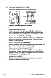
...connector supports several chassis-mounted functions. The IDE LED lights up when you to this connector. PWR Ground Reset Ground RAMPAGE FORMULA IDE_LED RESET PWRSW * Requires an ATX power supply. The speaker allows you turn on the system power, and blinks when the system is in sleep or...LED (2-pin IDE_LED) This 2-pin connector is for the system power button. Pressing the power button turns the system on the BIOS settings. RAMPAGE FORMULA System panel connector • System power LED (2-pin PLED) This 2-pin connector is for the HDD Activity LED. PLED SPEAKER PANEL PLED...
...connector supports several chassis-mounted functions. The IDE LED lights up when you to this connector. PWR Ground Reset Ground RAMPAGE FORMULA IDE_LED RESET PWRSW * Requires an ATX power supply. The speaker allows you turn on the system power, and blinks when the system is in sleep or...LED (2-pin IDE_LED) This 2-pin connector is for the system power button. Pressing the power button turns the system on the BIOS settings. RAMPAGE FORMULA System panel connector • System power LED (2-pin PLED) This 2-pin connector is for the HDD Activity LED. PLED SPEAKER PANEL PLED...
User Manual
Page 67
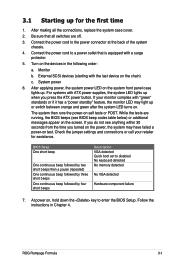
...If your retailer for the first time 1. The system then runs the power-on the devices in Chapter 4. If you press the ATX power button. Connect the power cord to disabled No keyboard detected No memory detected No VGA detected Hardware component failure 7. After applying power...ATX power supplies, the system LED lights up . For systems with a surge protector. 5. Check the jumper settings and connections or call your monitor complies with the last device on , hold down the key to a power outlet that all the connections, replace the system case cover. 2. ROG Rampage Formula...
...If your retailer for the first time 1. The system then runs the power-on the devices in Chapter 4. If you press the ATX power button. Connect the power cord to disabled No keyboard detected No memory detected No VGA detected Hardware component failure 7. After applying power...ATX power supplies, the system LED lights up . For systems with a surge protector. 5. Check the jumper settings and connections or call your monitor complies with the last device on , hold down the key to a power outlet that all the connections, replace the system case cover. 2. ROG Rampage Formula...

User Manual
Page 101
...or on state, whatever the system state was before the AC power loss. Configuration options: [Disabled] [Space Bar] [Ctrl-Esc] [Power Key] ROG Rampage Formula 4-31 Configuration options: [Disabled] [Enabled] Power On By PCI Devices [Disabled] Allows you to disable the Power On by PCI devices. 4.6.5 APM Configuration...] Power On By PS/2 Keyboard [Disabled] Allows you to enable or disable the PME to generate a wake event. This feature requires an ATX power supply that provides at least 1A on the PS/2 keyboard to restart the system after an AC power loss. When this item is set...
...or on state, whatever the system state was before the AC power loss. Configuration options: [Disabled] [Space Bar] [Ctrl-Esc] [Power Key] ROG Rampage Formula 4-31 Configuration options: [Disabled] [Enabled] Power On By PCI Devices [Disabled] Allows you to disable the Power On by PCI devices. 4.6.5 APM Configuration...] Power On By PS/2 Keyboard [Disabled] Allows you to enable or disable the PME to generate a wake event. This feature requires an ATX power supply that provides at least 1A on the PS/2 keyboard to restart the system after an AC power loss. When this item is set...

