User Guide
Page 13
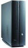
CF card slot . This slot is inserted in -1 card slot . This port connects a headphone with a stereo mini-plug. 16. USB 2.0 ports . ASUS Pundit P1-PH1 system 1-3 S/PDIF In port . Reset button . These Universal Serial Bus 2.0 (USB 2.0) ports are 8 located inside the front panel door. This port connects your audio ...
CF card slot . This slot is inserted in -1 card slot . This port connects a headphone with a stereo mini-plug. 16. USB 2.0 ports . ASUS Pundit P1-PH1 system 1-3 S/PDIF In port . Reset button . These Universal Serial Bus 2.0 (USB 2.0) ports are 8 located inside the front panel door. This port connects your audio ...
User Guide
Page 15
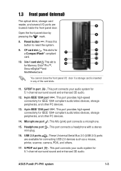
... this port becomes Front Speaker Out. 16. This socket connects the power cable and plug. This purple 6-pin connector is for a 17 PS/2 keyboard. 14. ASUS Pundit P1-PH1 system 1-5 PS/2 keyboard port . Line In port . The functions of this port becomes 14 Surround Speaker. 13 15. Audio ports function variation Port Blue...
... this port becomes Front Speaker Out. 16. This socket connects the power cable and plug. This purple 6-pin connector is for a 17 PS/2 keyboard. 14. ASUS Pundit P1-PH1 system 1-5 PS/2 keyboard port . Line In port . The functions of this port becomes 14 Surround Speaker. 13 15. Audio ports function variation Port Blue...
User Guide
Page 19
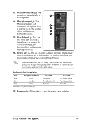
Keep the screws for later use. 4 3 3. Pull the cover slightly toward the rear panel until the cover tabs disengage from the chassis. 4. Lift the cover, then set aside. On the rear panel, locate the two screws that secure the cover to remove the cover screws. Use a Phillips (cross) screw driver to the chassis. 2. ASUS Pundit P1-PH1 system 2-3 2.3 Removing the cover To remove the cover: 2 1 1 1.
Keep the screws for later use. 4 3 3. Pull the cover slightly toward the rear panel until the cover tabs disengage from the chassis. 4. Lift the cover, then set aside. On the rear panel, locate the two screws that secure the cover to remove the cover screws. Use a Phillips (cross) screw driver to the chassis. 2. ASUS Pundit P1-PH1 system 2-3 2.3 Removing the cover To remove the cover: 2 1 1 1.
User Guide
Page 21
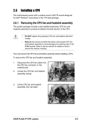
To remove the CPU fan and heatsink assembly: 1. Lift the CPU fan and heatsink assembly, then set aside. ASUS Pundit P1-PH1 system 2-5 Refer to the next section for Intel® Pentium® 4 processor in the 775-land package. 2.6.1 Removing the CPU fan and heatsink assembly ...
To remove the CPU fan and heatsink assembly: 1. Lift the CPU fan and heatsink assembly, then set aside. ASUS Pundit P1-PH1 system 2-5 Refer to the next section for Intel® Pentium® 4 processor in the 775-land package. 2.6.1 Removing the CPU fan and heatsink assembly ...
User Guide
Page 23
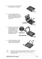
... load plate with your thumb and forefinger to a 100º angle (A), then push the PnP cap from the load plate window to a 135º angle. 4. ASUS Pundit P1-PH1 system 2-7 B The CPU fits in the direction of the socket. DO NOT force the CPU into the socket to prevent bending the connectors on...
... load plate with your thumb and forefinger to a 100º angle (A), then push the PnP cap from the load plate window to a 135º angle. 4. ASUS Pundit P1-PH1 system 2-7 B The CPU fits in the direction of the socket. DO NOT force the CPU into the socket to prevent bending the connectors on...
User Guide
Page 25
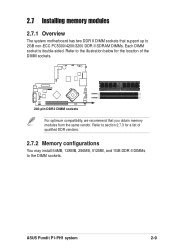
..., 128MB, 256MB, 512MB, and 1GB DDR II DIMMs to 2GB non-ECC PC5300/4200/3200 DDR II SDRAM DIMMs. Each DIMM socket is double-sided. ASUS Pundit P1-PH1 system 2-9 Refer to the illustration below for a list of the DIMM sockets. ® DIMMA1 DIMMB1 240-pin DDR2 DIMM sockets For optimum compatibility, we...
..., 128MB, 256MB, 512MB, and 1GB DDR II DIMMs to 2GB non-ECC PC5300/4200/3200 DDR II SDRAM DIMMs. Each DIMM socket is double-sided. ASUS Pundit P1-PH1 system 2-9 Refer to the illustration below for a list of the DIMM sockets. ® DIMMA1 DIMMB1 240-pin DDR2 DIMM sockets For optimum compatibility, we...
User Guide
Page 27
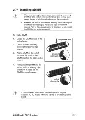
... retaining clip Locked retaining clip A DDR II DIMM is properly seated. Firmly insert the DIMM into a socket to reinstall the CPU fan and heatsink assembly. ASUS Pundit P1-PH1 system 2-11
... retaining clip Locked retaining clip A DDR II DIMM is properly seated. Firmly insert the DIMM into a socket to reinstall the CPU fan and heatsink assembly. ASUS Pundit P1-PH1 system 2-11
User Guide
Page 29
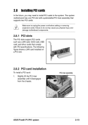
... adding or removing expansion cards. The following figure shows a LAN card installed on a PCI slot. 2.8.2 PCI card installation To install a PCI card: 1. PCI riser assembly ASUS Pundit P1-PH1 system 2-13 2.8 Installing PCI cards In the future, you may cause you physical injury and damage motherboard components. 2.8.1 PCI slots The PCI slots support...
... adding or removing expansion cards. The following figure shows a LAN card installed on a PCI slot. 2.8.2 PCI card installation To install a PCI card: 1. PCI riser assembly ASUS Pundit P1-PH1 system 2-13 2.8 Installing PCI cards In the future, you may cause you physical injury and damage motherboard components. 2.8.1 PCI slots The PCI slots support...
User Guide
Page 31
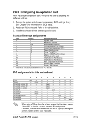
... and the card inoperable. Assign an IRQ to the tables below. 3. Install the software drivers for information on BIOS setup. 2. F G H -- -- -- -- -- -- -- -- -- -- -- -- -- -- -- -- -- -- -- -- -- -- -- -- Refer to the card. shared -- -- -- ASUS Pundit P1-PH1 system 2-15 used -- -- -- shared -- -- -- Turn on shared slots, ensure that the drivers support "Share IRQ" or that the cards do not need IRQ assignments...
... and the card inoperable. Assign an IRQ to the tables below. 3. Install the software drivers for information on BIOS setup. 2. F G H -- -- -- -- -- -- -- -- -- -- -- -- -- -- -- -- -- -- -- -- -- -- -- -- Refer to the card. shared -- -- -- ASUS Pundit P1-PH1 system 2-15 used -- -- -- shared -- -- -- Turn on shared slots, ensure that the drivers support "Share IRQ" or that the cards do not need IRQ assignments...
User Guide
Page 33
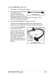
... a 4-pin (female) power plug from the PSU to the power connector at the back of the drive. 15-pin 4-pin (male) Serial ATA power cable ASUS Pundit P1-PH1 system 2-17 Connect one end of the supplied 7-pin SATA cable to the connector at the back of the Serial ATA cable drive, then...
... a 4-pin (female) power plug from the PSU to the power connector at the back of the drive. 15-pin 4-pin (male) Serial ATA power cable ASUS Pundit P1-PH1 system 2-17 Connect one end of the supplied 7-pin SATA cable to the connector at the back of the Serial ATA cable drive, then...
User Guide
Page 35
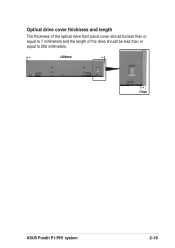
↓ ↓ ↓ Optical drive cover thickness and length The thickness of the optical drive front panel cover should be less than or equal to 7 millimeters and the length of the drive should be less than or equal to 208 millimeters. ≤208mm ≤7mm ASUS Pundit P1-PH1 system 2-19
↓ ↓ ↓ Optical drive cover thickness and length The thickness of the optical drive front panel cover should be less than or equal to 7 millimeters and the length of the drive should be less than or equal to 208 millimeters. ≤208mm ≤7mm ASUS Pundit P1-PH1 system 2-19
User Guide
Page 37
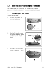
Follow the instructions to the chassis holes, then lay the foot stand over the chassis bottom. 1 Tab holes Hooks 2 3. Locate six tab holes on the bottom of the chassis. 2. Pull the foot stand toward the front panel until it fits in place. Align the foot stand hooks to remove or reinstall the foot stand. 2.11.1 Installing the foot stand To install the foot stand: 1. 2.11 Removing and reinstalling the foot stand The system comes with a removable foot stand for vertical desktop placement. ASUS Pundit P1-PH1 system 3 2-21
Follow the instructions to the chassis holes, then lay the foot stand over the chassis bottom. 1 Tab holes Hooks 2 3. Locate six tab holes on the bottom of the chassis. 2. Pull the foot stand toward the front panel until it fits in place. Align the foot stand hooks to remove or reinstall the foot stand. 2.11.1 Installing the foot stand To install the foot stand: 1. 2.11 Removing and reinstalling the foot stand The system comes with a removable foot stand for vertical desktop placement. ASUS Pundit P1-PH1 system 3 2-21
User Guide
Page 39
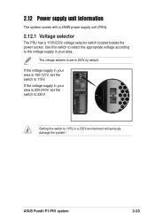
...-127V, set the switch to 115V. Setting the switch to 230V by default. If the voltage supply in a 230V environment will seriously damage the system! ASUS Pundit P1-PH1 system 2-23 2.12 Power supply unit information The system comes with a 250W power supply unit (PSU). 2.12.1 Voltage selector The PSU has a 115V/230V...
...-127V, set the switch to 115V. Setting the switch to 230V by default. If the voltage supply in a 230V environment will seriously damage the system! ASUS Pundit P1-PH1 system 2-23 2.12 Power supply unit information The system comes with a 250W power supply unit (PSU). 2.12.1 Voltage selector The PSU has a 115V/230V...
User Guide
Page 41
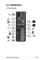
2.13 Connecting devices To the rear panel AC Line In Line Out Mic PS/2 KB USB DVI-D VGA Serial S-Video TV-out PS/2 Mouse RJ-45 Parallel ASUS Pundit P1-PH1 system 2-25
2.13 Connecting devices To the rear panel AC Line In Line Out Mic PS/2 KB USB DVI-D VGA Serial S-Video TV-out PS/2 Mouse RJ-45 Parallel ASUS Pundit P1-PH1 system 2-25
User Guide
Page 45
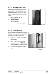
... with an installed optical drive, follow these instructions to insert a CD/DVD to the drive. Push the drive tray back to the drive. 1. Tray locks ASUS Pundit P1-PH1 system 3-3 Place a CD/DVD on the tray locks. 3. 3.3.2 Storage card slot A 3-in-1 storage card reader comes pre-installed in -1 card reader 3.3.3 Optical drive If...
... with an installed optical drive, follow these instructions to insert a CD/DVD to the drive. Push the drive tray back to the drive. 1. Tray locks ASUS Pundit P1-PH1 system 3-3 Place a CD/DVD on the tray locks. 3. 3.3.2 Storage card slot A 3-in-1 storage card reader comes pre-installed in -1 card reader 3.3.3 Optical drive If...
User Guide
Page 47
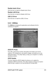
... on any detected problems. This utility helps you to install the Realtek Audio Driver. ASUS Update This item installs the ASUS Update that the motherboard supports. Realtek Audio Driver Click this item to update the motherboard BIOS and drivers. ASUS Pundit P1-PH1 system 3-5 Realtek LAN Driver Click this item to install the Realtek LAN...
... on any detected problems. This utility helps you to install the Realtek Audio Driver. ASUS Update This item installs the ASUS Update that the motherboard supports. Realtek Audio Driver Click this item to update the motherboard BIOS and drivers. ASUS Pundit P1-PH1 system 3-5 Realtek LAN Driver Click this item to install the Realtek LAN...

User Guide
Page 49
Browse this CD Displays the support CD contents in graphical format. Click an icon to display the specified information. ASUS Pundit P1-PH1 system 3-7 3.4.5 Other information The icons on the top right side of the screen give additional information on the motherboard and the contents of the motherboard. Motherboard info Displays the general specifications of the support CD.
Browse this CD Displays the support CD contents in graphical format. Click an icon to display the specified information. ASUS Pundit P1-PH1 system 3-7 3.4.5 Other information The icons on the top right side of the screen give additional information on the motherboard and the contents of the motherboard. Motherboard info Displays the general specifications of the support CD.
User Guide
Page 53
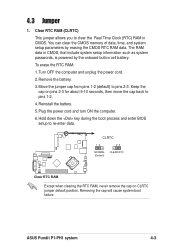
... erasing the CMOS RTC RAM data. You can clear the CMOS memory of date, time, and system setup parameters by the onboard button cell battery. ASUS Pundit P1-PH1 system 4-3 Remove the battery. 3.
... erasing the CMOS RTC RAM data. You can clear the CMOS memory of date, time, and system setup parameters by the onboard button cell battery. ASUS Pundit P1-PH1 system 4-3 Remove the battery. 3.
User Guide
Page 55
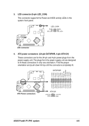
... +3 Volts -12 Volts Ground PSON# Ground Ground Ground -5 Volts +5 Volts +5 Volts +5 Volts Ground ATX12V ® ATX Power connectors ATX12V +12V DC GND +12V DC GND ASUS Pundit P1-PH1 system 4-5 LED connector (6-pin LED_CON) This connector supports the Power and HDD activity LEDs in only one orientation. The plugs from the power supply...
... +3 Volts -12 Volts Ground PSON# Ground Ground Ground -5 Volts +5 Volts +5 Volts +5 Volts Ground ATX12V ® ATX Power connectors ATX12V +12V DC GND +12V DC GND ASUS Pundit P1-PH1 system 4-5 LED connector (6-pin LED_CON) This connector supports the Power and HDD activity LEDs in only one orientation. The plugs from the power supply...

User Guide
Page 57
Serial port connector (10-1 pin COM1) This connector supports the rear panel serial port. ® Serial COM1 connector COM1 ASUS Pundit P1-PH1 system 4-7 The current Serial ATA interface allows up to 150 MB/s data transfer rate, faster than the standard parallel ATA with 133 MB/s (Ultra ...
Serial port connector (10-1 pin COM1) This connector supports the rear panel serial port. ® Serial COM1 connector COM1 ASUS Pundit P1-PH1 system 4-7 The current Serial ATA interface allows up to 150 MB/s data transfer rate, faster than the standard parallel ATA with 133 MB/s (Ultra ...
