User Guide
Page 4
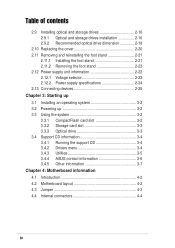
... information 2-23 2.12.1 Voltage selector 2-23 2.12.2 Power supply specifications 2-24 2.13 Connecting devices 2-25 Chapter 3: Starting up 3.1 Installing an operating system 3-2 3.2 Powering up 3-2 3.3 Using the system 3-2 3.3.1 CompactFlash card slot 3-2 3.3.2 Storage card slot 3-3 3.3.3 Optical drive 3-3 3.4 Support CD information 3-4 3.4.1 Running the support CD 3-4 3.4.2 Drivers menu 3-4 3.4.3 Utilities 3-5 3.4.4 ASUS contact information 3-6 3.4.5 Other information 3-7 Chapter 4: Motherboard information 4.1 Introduction...
... information 2-23 2.12.1 Voltage selector 2-23 2.12.2 Power supply specifications 2-24 2.13 Connecting devices 2-25 Chapter 3: Starting up 3.1 Installing an operating system 3-2 3.2 Powering up 3-2 3.3 Using the system 3-2 3.3.1 CompactFlash card slot 3-2 3.3.2 Storage card slot 3-3 3.3.3 Optical drive 3-3 3.4 Support CD information 3-4 3.4.1 Running the support CD 3-4 3.4.2 Drivers menu 3-4 3.4.3 Utilities 3-5 3.4.4 ASUS contact information 3-6 3.4.5 Other information 3-7 Chapter 4: Motherboard information 4.1 Introduction...

User Guide
Page 7
.... Entsorgung gebrauchter Batterien nach Angaben des Herstellers. Safety information Electrical safety • To prevent electrical shock hazard, disconnect the power cable from the electrical outlet before the signal cables are not damaged. Replace only with the same or equivalent type recommended...Operation safety • Before installing devices into the system, carefully read all cables are correctly connected and the power cables are connected. • If the power supply is incorrectly replaced. Place the product on a stable surface. • If you detect any area where ...
.... Entsorgung gebrauchter Batterien nach Angaben des Herstellers. Safety information Electrical safety • To prevent electrical shock hazard, disconnect the power cable from the electrical outlet before the signal cables are not damaged. Replace only with the same or equivalent type recommended...Operation safety • Before installing devices into the system, carefully read all cables are correctly connected and the power cables are connected. • If the power supply is incorrectly replaced. Place the product on a stable surface. • If you detect any area where ...
User Guide
Page 10
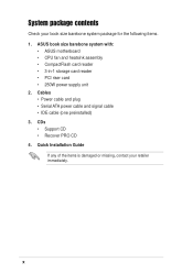
... and signal cable • IDE cable (one preinstalled) 3. ASUS book size barebone system with: • ASUS motherboard • CPU fan and heatsink assembly • CompactFlash card reader • 3-in-1 storage card reader • PCI riser card • 250W power supply unit 2. Quick Installation Guide If any of the items is damaged or missing, contact...
... and signal cable • IDE cable (one preinstalled) 3. ASUS book size barebone system with: • ASUS motherboard • CPU fan and heatsink assembly • CompactFlash card reader • 3-in-1 storage card reader • PCI riser card • 250W power supply unit 2. Quick Installation Guide If any of the items is damaged or missing, contact...

User Guide
Page 14
...you to a Local Area Network (LAN) through a network hub. 7. This port connects a television. 5. This green 6-pin connector is a 7 250W power supply unit. 10 8 3. This 25-pin port connects a printer, scanner, or other devices that allow convenient 1 connection of devices. 1. This port connects... a mouse, modem, or other devices. 8. DVI-D port. Power supply unit. TV-out port. This port allows connection to select the appropriate voltage supply in 3 your area. PCI slots. VGA port . These Universal Serial Bus 2.0 (USB 2.0) ports...
...you to a Local Area Network (LAN) through a network hub. 7. This port connects a television. 5. This green 6-pin connector is a 7 250W power supply unit. 10 8 3. This 25-pin port connects a printer, scanner, or other devices that allow convenient 1 connection of devices. 1. This port connects... a mouse, modem, or other devices. 8. DVI-D port. Power supply unit. TV-out port. This port allows connection to select the appropriate voltage supply in 3 your area. PCI slots. VGA port . These Universal Serial Bus 2.0 (USB 2.0) ports...
User Guide
Page 16
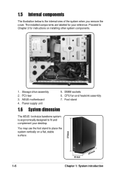
... riser 3. DIMM sockets 6. Foot stand 1.6 System dimension The ASUS booksize barebone system is the internal view of the system when you remove the cover. CPU fan and heatsink assembly 7. You may use the foot stand to Chapter 2 for your desktop. Storage drive assembly 2. Power supply unit 5. Proceed to place the system vertically on...
... riser 3. DIMM sockets 6. Foot stand 1.6 System dimension The ASUS booksize barebone system is the internal view of the system when you remove the cover. CPU fan and heatsink assembly 7. You may use the foot stand to Chapter 2 for your desktop. Storage drive assembly 2. Power supply unit 5. Proceed to place the system vertically on...
User Guide
Page 18
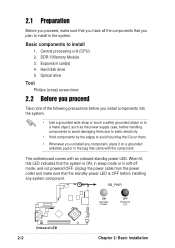
...you install components into the system. • Use a grounded wrist strap or touch a safely grounded object or to a metal object, such as the power supply case, before installing any component, place it on them due to static electricity. • Hold components by the edges to install in the system. ...The motherboard comes with the component. Unplug the power cable from the power outlet and make sure that you have all the components that you plan to avoid touching the ICs on a grounded antistatic pad or...
...you install components into the system. • Use a grounded wrist strap or touch a safely grounded object or to a metal object, such as the power supply case, before installing any component, place it on them due to static electricity. • Hold components by the edges to install in the system. ...The motherboard comes with the component. Unplug the power cable from the power outlet and make sure that you have all the components that you plan to avoid touching the ICs on a grounded antistatic pad or...
User Guide
Page 27
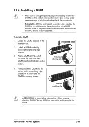
...CPU fan and heatsink assembly before adding or removing DIMMs or other system components. Refer to the previous section for details on the socket. 4. ASUS Pundit P1-PH1 system 2-11 To install a DIMM: 1. Firmly insert the DIMM into a socket to avoid damaging the DIMM. Align a DIMM on ...Unlocked retaining clip Locked retaining clip A DDR II DIMM is properly seated. 2.7.4 Installing a DIMM • Make sure to unplug the power supply before installing the DIMM(s) to avoid damaging the retaining clips of the DIMM sockets. Unlock a DIMM socket by pressing the retaining clips outward. 3....
...CPU fan and heatsink assembly before adding or removing DIMMs or other system components. Refer to the previous section for details on the socket. 4. ASUS Pundit P1-PH1 system 2-11 To install a DIMM: 1. Firmly insert the DIMM into a socket to avoid damaging the DIMM. Align a DIMM on ...Unlocked retaining clip Locked retaining clip A DDR II DIMM is properly seated. 2.7.4 Installing a DIMM • Make sure to unplug the power supply before installing the DIMM(s) to avoid damaging the retaining clips of the DIMM sockets. Unlock a DIMM socket by pressing the retaining clips outward. 3....
User Guide
Page 33
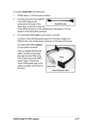
.... 15-pin 4-pin (male) Serial ATA power cable ASUS Pundit P1-PH1 system 2-17 See page 4-7 for the location of the previous section. 2. Connect a 4-pin plug (female) from the power supply unit (PSU) to the SATA connector on the motherboard. For Serial ATA HDDs without a 4-pin power connector: Use the supplied SATA power cable. Connect the 15-pin SATA...
.... 15-pin 4-pin (male) Serial ATA power cable ASUS Pundit P1-PH1 system 2-17 See page 4-7 for the location of the previous section. 2. Connect a 4-pin plug (female) from the power supply unit (PSU) to the SATA connector on the motherboard. For Serial ATA HDDs without a 4-pin power connector: Use the supplied SATA power cable. Connect the 15-pin SATA...
User Guide
Page 39
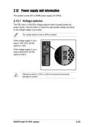
... is set the switch to 230V by default. 2.12 Power supply unit information The system comes with a 250W power supply unit (PSU). 2.12.1 Voltage selector The PSU has a 115V/230V voltage selector switch located beside the power socket. Use this switch to select the appropriate voltage according... to 230V. The voltage selector is 100-127V, set to 115V. If the voltage supply in a 230V environment will seriously damage the system! ASUS Pundit P1-PH1 system 2-23 Setting the...
... is set the switch to 230V by default. 2.12 Power supply unit information The system comes with a 250W power supply unit (PSU). 2.12.1 Voltage selector The PSU has a 115V/230V voltage selector switch located beside the power socket. Use this switch to select the appropriate voltage according... to 230V. The voltage selector is 100-127V, set to 115V. If the voltage supply in a 230V environment will seriously damage the system! ASUS Pundit P1-PH1 system 2-23 Setting the...

User Guide
Page 40
... and output full load Meet IEC61000-3-2 Class D (input power from 75W to 63 Hz 7A max. By shorting +5VSB, the power supply can latch down and latch off for shorting +5V, +12V, -12V, or +3.3V. 2.12.2 Power supply specifications Input Characteristics Input Voltage Range Range 1 Range 2 ...120mVp-p 120mVp-p 50mVp-p 50mVp-p Over-Voltage Protection (OVP) Output Voltage +5V +3.3V +12V +5VSB Maximum Voltage 6.5V 4.6V 15.5V 7V The power supply will shut down or automatically recover when the fault condition is removed 2-24 Chapter 2: Basic installation at 230Vac, full load 65% min. continue...
... and output full load Meet IEC61000-3-2 Class D (input power from 75W to 63 Hz 7A max. By shorting +5VSB, the power supply can latch down and latch off for shorting +5V, +12V, -12V, or +3.3V. 2.12.2 Power supply specifications Input Characteristics Input Voltage Range Range 1 Range 2 ...120mVp-p 120mVp-p 50mVp-p 50mVp-p Over-Voltage Protection (OVP) Output Voltage +5V +3.3V +12V +5VSB Maximum Voltage 6.5V 4.6V 15.5V 7V The power supply will shut down or automatically recover when the fault condition is removed 2-24 Chapter 2: Basic installation at 230Vac, full load 65% min. continue...
User Guide
Page 55
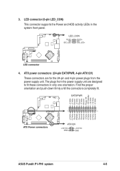
...pin ATX12V) These connectors are for the 24-pin and 4-pin power plugs from the power supply unit are designed to fit these connectors in the system front panel. The plugs from the power supply unit. Find the proper orientation and push down firmly until the ...connector 4. EATXPWR +3 Volts +3 Volts Ground +5 Volts Ground +5 Volts Ground Power OK +5V Standby +12 Volts +12 Volts +3 Volts +3 Volts -12 Volts Ground PSON# Ground Ground Ground -5 Volts +5 Volts +5 Volts +5 Volts Ground ATX12V ® ATX Power connectors ATX12V +12V DC GND +12V DC GND ASUS Pundit P1-PH1 system 4-5
...pin ATX12V) These connectors are for the 24-pin and 4-pin power plugs from the power supply unit are designed to fit these connectors in the system front panel. The plugs from the power supply unit. Find the proper orientation and push down firmly until the ...connector 4. EATXPWR +3 Volts +3 Volts Ground +5 Volts Ground +5 Volts Ground Power OK +5V Standby +12 Volts +12 Volts +3 Volts +3 Volts -12 Volts Ground PSON# Ground Ground Ground -5 Volts +5 Volts +5 Volts +5 Volts Ground ATX12V ® ATX Power connectors ATX12V +12V DC GND +12V DC GND ASUS Pundit P1-PH1 system 4-5

User Guide
Page 79
... +5VSB lead. Key-in a value (Min=0, Max=23), then press . 3. Highlight this item and press to the minutes field, then press . 4. ASUS Pundit P1-PH1 system 5-21 Key-in a value (Min=0, Max=59), then press . When this item is enabled, you can set the date and time of alarm... (Min=0, Max=59), then press . 5. Press tab to move to display a pop-up menu. This feature requires an ATX power supply that provides at least 1A on the system through a PCI modem. Configuration options: [Disabled] [Enabled] Power On By RTC Alarm [Disabled] Allows you to the seconds field, then press . 6.
... +5VSB lead. Key-in a value (Min=0, Max=23), then press . 3. Highlight this item and press to the minutes field, then press . 4. ASUS Pundit P1-PH1 system 5-21 Key-in a value (Min=0, Max=59), then press . When this item is enabled, you can set the date and time of alarm... (Min=0, Max=59), then press . 5. Press tab to move to display a pop-up menu. This feature requires an ATX power supply that provides at least 1A on the system through a PCI modem. Configuration options: [Disabled] [Enabled] Power On By RTC Alarm [Disabled] Allows you to the seconds field, then press . 6.
User Guide
Page 80
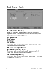
... CPU FAN Speed [Enabled] [1.23V] 3.26V 5.02V 12.28V 54oC 38oC 7273 RPM Select Menu Item Specific Help Press [Enter] to enable or disable the ASUS Q-Fan feature that smartly adjusts the CPU or chassis fan speed for more efficient system operation. CPU FAN Speed [xxxxRPM] The onboard hardware monitor automatically... fan speeds in these fields. CPU Temperature [xxxºC/xxxºF] M/B Temperature [xxxºC/xxxºF] The onboard hardware monitor automatically detects and display the power supply and CPU temperatures in rotations per minute (RPM). 5-22 Chapter 5: BIOS setup
... CPU FAN Speed [Enabled] [1.23V] 3.26V 5.02V 12.28V 54oC 38oC 7273 RPM Select Menu Item Specific Help Press [Enter] to enable or disable the ASUS Q-Fan feature that smartly adjusts the CPU or chassis fan speed for more efficient system operation. CPU FAN Speed [xxxxRPM] The onboard hardware monitor automatically... fan speeds in these fields. CPU Temperature [xxxºC/xxxºF] M/B Temperature [xxxºC/xxxºF] The onboard hardware monitor automatically detects and display the power supply and CPU temperatures in rotations per minute (RPM). 5-22 Chapter 5: BIOS setup