
User Guide
Page 12
Package contents Check your motherboard package for the following items. Motherboard Cables Accessories Application DVD Documentation ASUS PRIME X399-A motherboard 4 x Serial ATA 6.0 Gb/s cables 1 x ASUS SLI HB BRIDGE (2-WAY-M) 1 x Q-Connector 1 x M.2 vertical bracket 1 x M.2 screw package 1 x ASUS Q-Shield Motherboard support DVD User manual If any of the above items is damaged or missing, contact your retailer. xii
Package contents Check your motherboard package for the following items. Motherboard Cables Accessories Application DVD Documentation ASUS PRIME X399-A motherboard 4 x Serial ATA 6.0 Gb/s cables 1 x ASUS SLI HB BRIDGE (2-WAY-M) 1 x Q-Connector 1 x M.2 vertical bracket 1 x M.2 screw package 1 x ASUS Q-Shield Motherboard support DVD User manual If any of the above items is damaged or missing, contact your retailer. xii

User Guide
Page 15
... you install or remove any component, ensure that the ATX power supply is switched off or the power cord is detached from the power supply. ASUS PRIME X399-A 1-1 Chapter 1 Chapter 1: Product Introduction Product Introduction 1 1.1 Motherboard overview 1.1.1 Before you proceed Take note of the following precautions before you install motherboard components or change any...
... you install or remove any component, ensure that the ATX power supply is switched off or the power cord is detached from the power supply. ASUS PRIME X399-A 1-1 Chapter 1 Chapter 1: Product Introduction Product Introduction 1 1.1 Motherboard overview 1.1.1 Before you proceed Take note of the following precautions before you install motherboard components or change any...
User Guide
Page 17
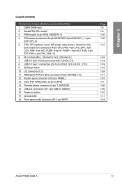
... button 17. Front panel audio connector (10-1 pin AAFP) Page 1-5 1-4 1-25 1-22 1-21 1-24 1-18 1-19 1-10 1-24 1-17 1-23 1-9 1-20 1-20 1-10 1-11 1-18 ASUS PRIME X399-A 1-3 Thermal sensor connector (2-pin T_SENSOR) 15. RGB header (4-pin RGB_HEADER1-2) 4. Chapter 1 Layout contents Connectors/Jumpers/Buttons and switches/Slots 1. Clear RTC RAM jumper (2-pin CLRTC...
... button 17. Front panel audio connector (10-1 pin AAFP) Page 1-5 1-4 1-25 1-22 1-21 1-24 1-18 1-19 1-10 1-24 1-17 1-23 1-9 1-20 1-20 1-10 1-11 1-18 ASUS PRIME X399-A 1-3 Thermal sensor connector (2-pin T_SENSOR) 15. RGB header (4-pin RGB_HEADER1-2) 4. Chapter 1 Layout contents Connectors/Jumpers/Buttons and switches/Slots 1. Clear RTC RAM jumper (2-pin CLRTC...

User Guide
Page 19
A DDR4 module is notched differently from a DDR, DDR2, or DDR3 module. PRIME X399-A 288-pin DDR4 DIMM sockets Recommended memory configurations ASUS PRIME X399-A 1-5 DIMM_D1* DIMM_D2 DIMM_C1* DIMM_C2 DIMM_A2 DIMM_A1* DIMM_B2 DIMM_B1* Chapter 1 1.1.4 System memory The motherboard comes with eight DDR4 (Double Data Rate 4) Dual Inline Memory Modules (DIMM) slots. DO NOT install a DDR, DDR2, or DDR3 memory module to the DDR4 slot.
A DDR4 module is notched differently from a DDR, DDR2, or DDR3 module. PRIME X399-A 288-pin DDR4 DIMM sockets Recommended memory configurations ASUS PRIME X399-A 1-5 DIMM_D1* DIMM_D2 DIMM_C1* DIMM_C2 DIMM_A2 DIMM_A1* DIMM_B2 DIMM_B1* Chapter 1 1.1.4 System memory The motherboard comes with eight DDR4 (Double Data Rate 4) Dual Inline Memory Modules (DIMM) slots. DO NOT install a DDR, DDR2, or DDR3 memory module to the DDR4 slot.

User Guide
Page 21
Failure to do so may cause you physical injury and damage motherboard components. 1.1.5 Expansion slots Unplug the power cord before adding or removing expansion cards. Chapter 1 PCIEX16_1 PCIEX4 PCIEX16_2 PCIEX16_3 PCIEX1 PCIEX16_4 Slot No. 1 2 3 4 5 6 Slot Description PCIe 3.0/2.0 x16_1 slot PCIe 2.0 x4 slot PCIe 3.0/2.0 x16_2 slot PCIe 3.0/2.0 x16_3 slot PCIe 2.0 x1 slot PCIe 3.0/2.0 x16_4 slot ASUS PRIME X399-A 1-7
Failure to do so may cause you physical injury and damage motherboard components. 1.1.5 Expansion slots Unplug the power cord before adding or removing expansion cards. Chapter 1 PCIEX16_1 PCIEX4 PCIEX16_2 PCIEX16_3 PCIEX1 PCIEX16_4 Slot No. 1 2 3 4 5 6 Slot Description PCIe 3.0/2.0 x16_1 slot PCIe 2.0 x4 slot PCIe 3.0/2.0 x16_2 slot PCIe 3.0/2.0 x16_3 slot PCIe 2.0 x1 slot PCIe 3.0/2.0 x16_4 slot ASUS PRIME X399-A 1-7

User Guide
Page 23
... seconds. 3. For system failure due to clear the Real Time Clock (RTC) RAM in CMOS, which include system setup information such as system passwords. Chapter 1 PRIME X399-A Clear RTC RAM CLRTC PIN 1 To erase the RTC RAM: 1. Plug the power cord and turn on the CLRTC jumper. Placing a metal object or jumper... to clear the CMOS RTC RAM data. Clear RTC RAM jumper (2-pin CLRTC) This jumper allows you to overclocking, use the C.P.R. (CPU Parameter Recall) feature. ASUS PRIME X399-A 1-9
... seconds. 3. For system failure due to clear the Real Time Clock (RTC) RAM in CMOS, which include system setup information such as system passwords. Chapter 1 PRIME X399-A Clear RTC RAM CLRTC PIN 1 To erase the RTC RAM: 1. Plug the power cord and turn on the CLRTC jumper. Placing a metal object or jumper... to clear the CMOS RTC RAM data. Clear RTC RAM jumper (2-pin CLRTC) This jumper allows you to overclocking, use the C.P.R. (CPU Parameter Recall) feature. ASUS PRIME X399-A 1-9
User Guide
Page 25
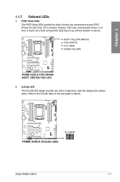
BOOT (YELLOW GREEN) VGA (WHITE) CPU (RED) DRAM (YELLOW) PRIME X399-A CPU/ DRAM/ BOOT_DEVICE/ VGA LED 2. If an error is found, the critical component's LED stays lit up until the problem is solved. Refer to the Q-... table on the next page for details. Q-Code LED The Q-Code LED design provides you with a 2-digit error code that displays the system status. PRIME X399-A Q-Code LEDs ASUS PRIME X399-A 1-11 POST State LEDs The POST State LEDs provide the status of these key components during POST (Power-On Self-Test): CPU, memory modules...
BOOT (YELLOW GREEN) VGA (WHITE) CPU (RED) DRAM (YELLOW) PRIME X399-A CPU/ DRAM/ BOOT_DEVICE/ VGA LED 2. If an error is found, the critical component's LED stays lit up until the problem is solved. Refer to the Q-... table on the next page for details. Q-Code LED The Q-Code LED design provides you with a 2-digit error code that displays the system status. PRIME X399-A Q-Code LEDs ASUS PRIME X399-A 1-11 POST State LEDs The POST State LEDs provide the status of these key components during POST (Power-On Self-Test): CPU, memory modules...

User Guide
Page 27
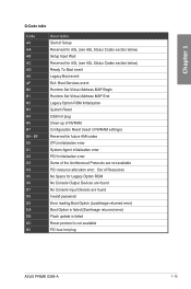
... Agent DXE initialization is started System Agent DXE SMM initialization is started System Agent DXE initialization (System Agent module specific) (continued on the next page) ASUS PRIME X399-A 1-13 E7 E8 E9 EA EB EC - F7 F8 F9 FA FB - EF F0 F1 F2 F3 F4 F5 - Chapter 1 Q-Code table Code 5A 5B...
... Agent DXE initialization is started System Agent DXE SMM initialization is started System Agent DXE initialization (System Agent module specific) (continued on the next page) ASUS PRIME X399-A 1-13 E7 E8 E9 EA EB EC - F7 F8 F9 FA FB - EF F0 F1 F2 F3 F4 F5 - Chapter 1 Q-Code table Code 5A 5B...
User Guide
Page 29
... Boot Option (LoadImage returned error) Boot Option is failed (StartImage returned error) Flash update is failed Reset protocol is not available PCI bus hot plug ASUS PRIME X399-A 1-15 Chapter 1 Q-Code table Code A9 AA AB AC AD AE AF B0 B1 B2 B3 B4 B6 B7 B8-
... Boot Option (LoadImage returned error) Boot Option is failed (StartImage returned error) Flash update is failed Reset protocol is not available PCI bus hot plug ASUS PRIME X399-A 1-15 Chapter 1 Q-Code table Code A9 AA AB AC AD AE AF B0 B1 B2 B3 B4 B6 B7 B8-

User Guide
Page 31
If you can create a RAID 0, 1, and 10 configuration through the onboard AMD X399 chipset. ASUS PRIME X399-A 1-17 AMD Serial ATA 6.0 Gb/s connectors (7-pin SATA6G_1-6) These connectors connect to [AHCI] by default. Chapter 1 PRIME X399-A Serial ATA 6.0Gb/s connectors These connectors are set the SATA Mode Selection item in the BIOS to [RAID]. 1.1.8 Internal connectors 1. If you installed Serial ATA hard disk drives, you intend to create a Serial ATA RAID set using these connectors, set to Serial ATA 6.0 Gb/s hard disk drives via Serial ATA 6.0 Gb/s signal cables.
If you can create a RAID 0, 1, and 10 configuration through the onboard AMD X399 chipset. ASUS PRIME X399-A 1-17 AMD Serial ATA 6.0 Gb/s connectors (7-pin SATA6G_1-6) These connectors connect to [AHCI] by default. Chapter 1 PRIME X399-A Serial ATA 6.0Gb/s connectors These connectors are set the SATA Mode Selection item in the BIOS to [RAID]. 1.1.8 Internal connectors 1. If you installed Serial ATA hard disk drives, you intend to create a Serial ATA RAID set using these connectors, set to Serial ATA 6.0 Gb/s hard disk drives via Serial ATA 6.0 Gb/s signal cables.

User Guide
Page 33
... 1 module, you to 5 Gb/s, faster charging time for additional USB 3.1 Gen 1 front or rear panel ports. Vbus PIN 1 A PIN 1 B PRIME X399-A USB 3.1 Gen 1 connectors The USB 3.1 Gen 1 module is purchased separately. Chapter 1 4. ASUS PRIME X399-A 1-19 GND IntA_P1_SSTX+ IntA_P1_SSTX- U31G1_1112) These connectors allow you can enjoy all the benefits of USB 3.1 Gen 1 including faster data...
... 1 module, you to 5 Gb/s, faster charging time for additional USB 3.1 Gen 1 front or rear panel ports. Vbus PIN 1 A PIN 1 B PRIME X399-A USB 3.1 Gen 1 connectors The USB 3.1 Gen 1 module is purchased separately. Chapter 1 4. ASUS PRIME X399-A 1-19 GND IntA_P1_SSTX+ IntA_P1_SSTX- U31G1_1112) These connectors allow you can enjoy all the benefits of USB 3.1 Gen 1 including faster data...
User Guide
Page 35
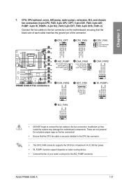
Insufficient air flow inside the system may damage the motherboard components. ASUS PRIME X399-A 1-21 Do not place jumper caps on water cooling device. • Connect the fan of the connector. These are not jumpers! A B C D E F G H I J PRIME X399-A Fan connectors A CPU_OPT B CPU_FAN CPU FAN PWM CPU FAN IN CPU FAN PWR GND CPU FAN PWM CPU FAN...
Insufficient air flow inside the system may damage the motherboard components. ASUS PRIME X399-A 1-21 Do not place jumper caps on water cooling device. • Connect the fan of the connector. These are not jumpers! A B C D E F G H I J PRIME X399-A Fan connectors A CPU_OPT B CPU_FAN CPU FAN PWM CPU FAN IN CPU FAN PWR GND CPU FAN PWM CPU FAN...

User Guide
Page 37
PWRSW SPEAKER PANEL PIN 1 +HDD_LED- Connect the chassis power LED cable to this connector. PRIME X399-A System panel connector • System power LED (2-pin or 3-1 pin PWR_LED) The 2-pin or 3-1 pin connector is for the chassis-mounted reset button for system ... button turns the system on or puts the system in sleep or soft-off button (2-pin PWRSW) This connector is for the system power button. ASUS PRIME X399-A 1-23 Chapter 1 PLED+ PLEDPWRBTN# GND +5V Ground Ground Speaker HDD_LED+ HDD_LED- Pressing the power switch for more than four seconds while the system is ON...
PWRSW SPEAKER PANEL PIN 1 +HDD_LED- Connect the chassis power LED cable to this connector. PRIME X399-A System panel connector • System power LED (2-pin or 3-1 pin PWR_LED) The 2-pin or 3-1 pin connector is for the chassis-mounted reset button for system ... button turns the system on or puts the system in sleep or soft-off button (2-pin PWRSW) This connector is for the system power button. ASUS PRIME X399-A 1-23 Chapter 1 PLED+ PLEDPWRBTN# GND +5V Ground Ground Speaker HDD_LED+ HDD_LED- Pressing the power switch for more than four seconds while the system is ON...

User Guide
Page 39
... is switched off or the power cord is purchased separately. A A RGB_HEADER2 PIN 1 +12V G R B B RGB_HEADER1 PIN 1 +12V G R B B B R G 12V PRIME X399-A RGB headers These RGB headers support 5050 RGB multi-color LED strips (12V/G/R/B), with the 12V header on the motherboard. • The LED strip will...8226; If your LED strip does not light up under the operating system. • The LED strip is detached from the power supply. ASUS PRIME X399-A 1-25 Failure to do so may cause severe damage to the motherboard, peripherals, or components. • Actual lighting and color will ...
... is switched off or the power cord is purchased separately. A A RGB_HEADER2 PIN 1 +12V G R B B RGB_HEADER1 PIN 1 +12V G R B B B R G 12V PRIME X399-A RGB headers These RGB headers support 5050 RGB multi-color LED strips (12V/G/R/B), with the 12V header on the motherboard. • The LED strip will...8226; If your LED strip does not light up under the operating system. • The LED strip is detached from the power supply. ASUS PRIME X399-A 1-25 Failure to do so may cause severe damage to the motherboard, peripherals, or components. • Actual lighting and color will ...

User Guide
Page 41
... same for the SocketTR4 socket. Ensure you use a CPU designed for all models. 2.1.1 CPU installation Unplug all power cables before installing the CPU. A A Rail frame ASUS PRIME X399-A B 2-1 The CPU fits in sequence 3>2>1, then lift the load plate. The AMD SocketTR4 socket is compatible with models, but the installation steps are for reference...
... same for the SocketTR4 socket. Ensure you use a CPU designed for all models. 2.1.1 CPU installation Unplug all power cables before installing the CPU. A A Rail frame ASUS PRIME X399-A B 2-1 The CPU fits in sequence 3>2>1, then lift the load plate. The AMD SocketTR4 socket is compatible with models, but the installation steps are for reference...

User Guide
Page 43
2.1.2 CPU heatsink and fan assembly installation To install the CPU heatsink and fan assembly: Chapter 2 ASUS PRIME X399-A 2-3
2.1.2 CPU heatsink and fan assembly installation To install the CPU heatsink and fan assembly: Chapter 2 ASUS PRIME X399-A 2-3

User Guide
Page 45
Doing so can damage the motherboard. Chapter 2 PRIME X399-A DO NOT overtighten the screws! 3. ASUS PRIME X399-A 2-5 Place nine screws into the holes indicated by circles to secure the motherboard to the chassis.
Doing so can damage the motherboard. Chapter 2 PRIME X399-A DO NOT overtighten the screws! 3. ASUS PRIME X399-A 2-5 Place nine screws into the holes indicated by circles to secure the motherboard to the chassis.

User Guide
Page 47
2.1.5 ATX power connection Chapter 2 OR AND • DO NOT connect the 4-pin power plug only, the motherboard may overheat under heavy usage. • Ensure to connect the 8-pin power plug, or connect both the 8-pin and 4-pin power plugs. ASUS PRIME X399-A 2-7
2.1.5 ATX power connection Chapter 2 OR AND • DO NOT connect the 4-pin power plug only, the motherboard may overheat under heavy usage. • Ensure to connect the 8-pin power plug, or connect both the 8-pin and 4-pin power plugs. ASUS PRIME X399-A 2-7

User Guide
Page 49
Push the connector until it clicks into place. To install USB 3.1 Gen 1 connector To install USB 2.0 connector USB 3.1 Gen 1 To install front panel audio connector USB 2.0 AAFP ASUS PRIME X399-A 2-9 Chapter 2 2.1.7 Front I/O connector To install ASUS Q-Connector To install USB 3.1 Gen 2 connector USB 3.1 Gen 2 This connector will only fit in one orientation.
Push the connector until it clicks into place. To install USB 3.1 Gen 1 connector To install USB 2.0 connector USB 3.1 Gen 1 To install front panel audio connector USB 2.0 AAFP ASUS PRIME X399-A 2-9 Chapter 2 2.1.7 Front I/O connector To install ASUS Q-Connector To install USB 3.1 Gen 2 connector USB 3.1 Gen 2 This connector will only fit in one orientation.

User Guide
Page 51
ASUS PRIME X399-A 2-11 2.1.9 M.2 installation OR Chapter 2 Supported M.2 type varies per motherboard.
ASUS PRIME X399-A 2-11 2.1.9 M.2 installation OR Chapter 2 Supported M.2 type varies per motherboard.


