
E11133MBPinDefinition English
Page 6
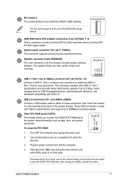
... 1A (12 W) fan power. USB 3.0 connector (20-1 pin) This connector allows you can enjoy all the benefits of USB 3.0 including faster data transfer speeds of up to 5 Gbps, faster charging time for additional USB 3.0 front or rear panel ports. Connect the USB module cable USB to... this connector, then install the module to connect a USB 3.0 module for USB-chargeable devices, optimized power efficiency, and PIN 1...
... 1A (12 W) fan power. USB 3.0 connector (20-1 pin) This connector allows you can enjoy all the benefits of USB 3.0 including faster data transfer speeds of up to 5 Gbps, faster charging time for additional USB 3.0 front or rear panel ports. Connect the USB module cable USB to... this connector, then install the module to connect a USB 3.0 module for USB-chargeable devices, optimized power efficiency, and PIN 1...

E11133MBPinDefinition English
Page 8
... (S/PDIF) SPDIF_OUT port. LPT standardizes as a printer. Digital audio connector (4-1 pin SPDIF_OUT) This connector is the parallel port interface on the motherboard. Refer to this connector. Connect one end of the front panel audio I /O module that you connect a high-definition front panel audio module to this connector to avail of the system chassis. +5V SPDIFOUT GND...
... (S/PDIF) SPDIF_OUT port. LPT standardizes as a printer. Digital audio connector (4-1 pin SPDIF_OUT) This connector is the parallel port interface on the motherboard. Refer to this connector. Connect one end of the front panel audio I /O module that you connect a high-definition front panel audio module to this connector to avail of the system chassis. +5V SPDIFOUT GND...

E11133MBPinDefinition English
Page 10
... • Hard disk drive activity LED (2-pin HDD_LED) SPEAKER HDD_LED+ HDD_LED- Connect the HDD Activity LED cable to this connector. System panel connector (10-1 pin F_PANEL) This connector supports several chassis-mounted functions. • System power LED (2-pin PWR_LED) F_PANEL +PWR_LED- Connect the HDD Activity LED cable...mode. The system power LED lights up or flashes when data is for the HDD Activity LED. System panel connector (20-8 pin PANEL) This connector supports several chassis-mounted functions. The system power LED lights up or flashes when data is for the ...
... • Hard disk drive activity LED (2-pin HDD_LED) SPEAKER HDD_LED+ HDD_LED- Connect the HDD Activity LED cable to this connector. System panel connector (10-1 pin F_PANEL) This connector supports several chassis-mounted functions. • System power LED (2-pin PWR_LED) F_PANEL +PWR_LED- Connect the HDD Activity LED cable...mode. The system power LED lights up or flashes when data is for the HDD Activity LED. System panel connector (20-8 pin PANEL) This connector supports several chassis-mounted functions. The system power LED lights up or flashes when data is for the ...

E11133MBPinDefinition English
Page 11
... the chassis-mounted reset button for system reboot without turning off button (2-pin PWR_SW) This connector is for the HDD Activity LED. Connect the HDD Activity LED cable to this connector. The HDD LED lights up when you to the HDD. +HDD_LED- Pressing the power...the system OFF. • Reset button (2-pin RESET) This 2-pin connector is read from or written to hear system beeps and warnings. • ATX power button/soft-off the system power. System panel connector (20-5 pin PANEL) This connector supports several chassis-mounted functions. • System power LED (4-pin ...
... the chassis-mounted reset button for system reboot without turning off button (2-pin PWR_SW) This connector is for the HDD Activity LED. Connect the HDD Activity LED cable to this connector. The HDD LED lights up when you to the HDD. +HDD_LED- Pressing the power...the system OFF. • Reset button (2-pin RESET) This 2-pin connector is read from or written to hear system beeps and warnings. • ATX power button/soft-off the system power. System panel connector (20-5 pin PANEL) This connector supports several chassis-mounted functions. • System power LED (4-pin ...

E11133MBPinDefinition English
Page 12
...- Connect one end of the chassis intrusion sensor or switch cable to this connector. GND you to the HDD. • System warning speaker (4-pin SPEAKER) This 4-pin connector is for the chassis-mounted system warning speaker. System panel connector (20-3 pin F_PANEL) This connector supports several chassis-mounted functions. • System power LED (4-pin +PWR_LED...
...- Connect one end of the chassis intrusion sensor or switch cable to this connector. GND you to the HDD. • System warning speaker (4-pin SPEAKER) This 4-pin connector is for the chassis-mounted system warning speaker. System panel connector (20-3 pin F_PANEL) This connector supports several chassis-mounted functions. • System power LED (4-pin +PWR_LED...

E11133MBPinDefinition English
Page 14
...PIN 1 24. Internal DC power connector (2-pin ATX19V) This connector is for the LCD panel backlight and brightness controls. Find the proper orientation and push down firmly until the connector completely fits. LCD panel monitor switch header (2-pin PANEL_SW) ... BKLT_PWR BKLT_GND/Brightness_GND BKLT_GND/Brightness_GND Brightness_up Brightness_Down 21. INT_SPK Front_L- 20. Flat panel display brightness connector (8-pin LCD_BLKT_PANEL) This connector is designed to fit this connector in only one orientation. Find the proper orientation and push down firmly until the...
...PIN 1 24. Internal DC power connector (2-pin ATX19V) This connector is for the LCD panel backlight and brightness controls. Find the proper orientation and push down firmly until the connector completely fits. LCD panel monitor switch header (2-pin PANEL_SW) ... BKLT_PWR BKLT_GND/Brightness_GND BKLT_GND/Brightness_GND Brightness_up Brightness_Down 21. INT_SPK Front_L- 20. Flat panel display brightness connector (8-pin LCD_BLKT_PANEL) This connector is designed to fit this connector in only one orientation. Find the proper orientation and push down firmly until the...
Users Manual English
Page 8
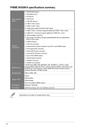
viii PRIME B450M-K specifications summary Rear panel I/O ports Internal connectors BIOS features Manageability Support DVD OS support Form factor 1 x PS/2 Keyboard port 1 x PS/2 Mouse port 1 x D-Sub port 1 x DVI-D port 1 x LAN (RJ-45) port 2 x USB 3.1 Gen 2 ports 4 x USB 3.1 Gen 1 ports 3 x Audio jacks support 8-channel audio output 1 x USB 3.1 Gen 1 connector supports additional 2 USB 3.1 Gen 1 ports 2 x USB 2.0/1.1 connectors support additional...
viii PRIME B450M-K specifications summary Rear panel I/O ports Internal connectors BIOS features Manageability Support DVD OS support Form factor 1 x PS/2 Keyboard port 1 x PS/2 Mouse port 1 x D-Sub port 1 x DVI-D port 1 x LAN (RJ-45) port 2 x USB 3.1 Gen 2 ports 4 x USB 3.1 Gen 1 ports 3 x Audio jacks support 8-channel audio output 1 x USB 3.1 Gen 1 connector supports additional 2 USB 3.1 Gen 1 ports 2 x USB 2.0/1.1 connectors support additional...
Users Manual English
Page 11
... RTC RAM data of up to this connector for the chassis-mounted system warning speaker. ASUS PRIME B450M-K 1-3 M.2 socket 3 This socket allows you to Serial ATA 6.0 Gb/s hard disk drives via Serial ATA 6.0 Gb/s signal cables. System panel connector (10-1 pin F_PANEL) This connector supports several chassis-mounted functions. This connector complies with USB 2.0 specifications and support up...
... RTC RAM data of up to this connector for the chassis-mounted system warning speaker. ASUS PRIME B450M-K 1-3 M.2 socket 3 This socket allows you to Serial ATA 6.0 Gb/s hard disk drives via Serial ATA 6.0 Gb/s signal cables. System panel connector (10-1 pin F_PANEL) This connector supports several chassis-mounted functions. This connector complies with USB 2.0 specifications and support up...

Users Manual English
Page 12
.... PCI Express 3.0 / 2.0 x16 slot This motherboard supports one end of the front panel audio I /O module that complies with the PCI Express specifications. Serial port connector (10-1 pin COM) This connector is for an additional Sony/Philips Digital Interface (S/PDIF) port. PCI Express 2.0 x1 ... x1 network cards, SCSI cards, and other cards that you connect a high-definition front panel audio module to this connector, set the Front Panel Type item in the BIOS setup to this connector. • We recommend that comply with the PCI Express specifications. 1-4 Chapter 1: Product ...
.... PCI Express 3.0 / 2.0 x16 slot This motherboard supports one end of the front panel audio I /O module that complies with the PCI Express specifications. Serial port connector (10-1 pin COM) This connector is for an additional Sony/Philips Digital Interface (S/PDIF) port. PCI Express 2.0 x1 ... x1 network cards, SCSI cards, and other cards that you connect a high-definition front panel audio module to this connector, set the Front Panel Type item in the BIOS setup to this connector. • We recommend that comply with the PCI Express specifications. 1-4 Chapter 1: Product ...

Users Manual English
Page 13
... better performance from S5 mode Speed LED Status Description OFF 10Mbps connection ORANGE 100Mbps connection GREEN 1Gbps connection Activity Link Speed LED LED LAN port ASUS PRIME B450M-K 1-5 USB 3.1 Gen 1 (up to 10Gbps) ports (teal blue, Type A). Rear panel connectors 1 2 3 4 5 67 10 9 3 8 1. Video Graphics Adapter (VGA) port. LAN (RJ-45) port.
... better performance from S5 mode Speed LED Status Description OFF 10Mbps connection ORANGE 100Mbps connection GREEN 1Gbps connection Activity Link Speed LED LED LAN port ASUS PRIME B450M-K 1-5 USB 3.1 Gen 1 (up to 10Gbps) ports (teal blue, Type A). Rear panel connectors 1 2 3 4 5 67 10 9 3 8 1. Video Graphics Adapter (VGA) port. LAN (RJ-45) port.


