BIOSUpdateE-Manual English
Page 2
... carrier and the location where you give us a notification to duly provide complete source code as required under the same license as stated in the About Box of such software and/or other Free Open Source Software Licenses. SPECIFICATIONS AND INFORMATION CONTAINED IN THIS MANUAL ARE FURNISHED FOR INFORMATIONAL USE ONLY, AND ARE SUBJECT TO CHANGE AT ANY TIME...
... carrier and the location where you give us a notification to duly provide complete source code as required under the same license as stated in the About Box of such software and/or other Free Open Source Software Licenses. SPECIFICATIONS AND INFORMATION CONTAINED IN THIS MANUAL ARE FURNISHED FOR INFORMATIONAL USE ONLY, AND ARE SUBJECT TO CHANGE AT ANY TIME...
BIOSUpdateE-Manual English
Page 4
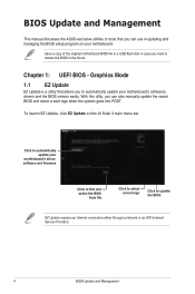
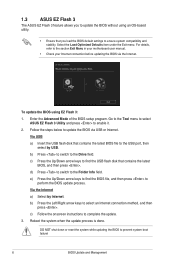
... motherboard BIOS file to a USB flash disk in case you need to restore the BIOS in updating and managing the BIOS setup program on the AI Suite 3 main menu bar. To launch EZ Update, click EZ Update on your motherboard. Graphics Mode 1.1 EZ Update EZ Update is a utility that you can also manually update the saved BIOS and select a boot logo when the system goes into POST. With this utlity, you can use in the future. Chapter 1: UEFI BIOS...
... motherboard BIOS file to a USB flash disk in case you need to restore the BIOS in updating and managing the BIOS setup program on the AI Suite 3 main menu bar. To launch EZ Update, click EZ Update on your motherboard. Graphics Mode 1.1 EZ Update EZ Update is a utility that you can also manually update the saved BIOS and select a boot logo when the system goes into POST. With this utlity, you can use in the future. Chapter 1: UEFI BIOS...
BIOSUpdateE-Manual English
Page 5
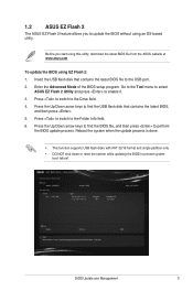
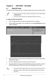
... Tool menu to select ASUS EZ Flash 2 Utility and press to the Folder Info field. 6. Press to switch to enable it. 3. Enter the Advanced Mode of the BIOS setup program. Before you to the USB port. 2. Insert the USB flash disk that contains the latest BIOS, and then press . 5. 1.2 ASUS EZ Flash 2 The ASUS EZ Flash 2 feature allows you start using this utility, download the latest BIOS file from the ASUS website at www.asus.com To update the BIOS using...
... Tool menu to select ASUS EZ Flash 2 Utility and press to the Folder Info field. 6. Press to switch to enable it. 3. Enter the Advanced Mode of the BIOS setup program. Before you to the USB port. 2. Insert the USB flash disk that contains the latest BIOS, and then press . 5. 1.2 ASUS EZ Flash 2 The ASUS EZ Flash 2 feature allows you start using this utility, download the latest BIOS file from the ASUS website at www.asus.com To update the BIOS using...
BIOSUpdateE-Manual English
Page 6
... Advanced Mode of the BIOS setup program. e) Press the Up/Down arrow keys to find the USB flash disk that contains the latest BIOS file to the USB port, then select by Internet. b) Press the Left/Right arrow keys to the Folder Info field. Select the Load Optimized Defaults item under the Exit menu. To update the BIOS using an OS‑based utility. • Ensure that you load the BIOS default settings...
... Advanced Mode of the BIOS setup program. e) Press the Up/Down arrow keys to find the USB flash disk that contains the latest BIOS file to the USB port, then select by Internet. b) Press the Left/Right arrow keys to the Folder Info field. Select the Load Optimized Defaults item under the Exit menu. To update the BIOS using an OS‑based utility. • Ensure that you load the BIOS default settings...

BIOSUpdateE-Manual English
Page 7
... 7 1.4 ASUS CrashFree BIOS 3 The ASUS CrashFree BIOS 3 is an auto recovery tool that you press to load default BIOS values. Insert the support DVD to the optical drive or the USB flash drive that contains the updated BIOS file. • Before using the motherboard support DVD or a USB flash drive that contains the BIOS file to recover BIOS settings. When found, the utility reads the BIOS file and enters ASUS EZ Flash 3 utility automatically. 4. You can cause system boot failure! The system requires you to enter BIOS Setup to the USB port. 3. Recovering...
... 7 1.4 ASUS CrashFree BIOS 3 The ASUS CrashFree BIOS 3 is an auto recovery tool that you press to load default BIOS values. Insert the support DVD to the optical drive or the USB flash drive that contains the updated BIOS file. • Before using the motherboard support DVD or a USB flash drive that contains the BIOS file to recover BIOS settings. When found, the utility reads the BIOS file and enters ASUS EZ Flash 3 utility automatically. 4. You can cause system boot failure! The system requires you to enter BIOS Setup to the USB port. 3. Recovering...
BIOSUpdateE-Manual English
Page 8
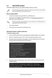
.... To update the BIOS using this utility, download the latest BIOS file from the ASUS website at www.asus.com • Check your Internet connection before updating the BIOS via the Internet. Go to the Tool menu to select Start EzFlash and press to prevent system boot failure! 8 BIOS Update and Management Insert the USB flash disk that contains the latest BIOS, and then press . 4. Press the Up/Down arrow keys to the USB port...
.... To update the BIOS using this utility, download the latest BIOS file from the ASUS website at www.asus.com • Check your Internet connection before updating the BIOS via the Internet. Go to the Tool menu to select Start EzFlash and press to prevent system boot failure! 8 BIOS Update and Management Insert the USB flash disk that contains the latest BIOS, and then press . 4. Press the Up/Down arrow keys to the USB port...
BIOSUpdateE-Manual English
Page 9
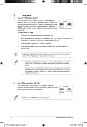
... boot using defaults P2: ST3808110AS (76319MB) aigo miniking (250MB) UEFI: (FAT) ASUS DRW-2014L1T(4458MB) P1: ASUS DRW-2014L1T(4458MB) UEFI: (FAT) aigo miniking (250MB) Enter Setup 4. Boot your computer screen. Please select boot device: and to move selection ENTER to select boot device ESC to launch the select boot device screen. 3. NTFS is detected. Peter Anvin A Bootable DVD/CD is not supported under FreeDOS environment. Ensure that your USB flash drive...
... boot using defaults P2: ST3808110AS (76319MB) aigo miniking (250MB) UEFI: (FAT) ASUS DRW-2014L1T(4458MB) P1: ASUS DRW-2014L1T(4458MB) UEFI: (FAT) aigo miniking (250MB) Enter Setup 4. Boot your computer screen. Please select boot device: and to move selection ENTER to select boot device ESC to launch the select boot device screen. 3. NTFS is detected. Peter Anvin A Bootable DVD/CD is not supported under FreeDOS environment. Ensure that your USB flash drive...

E11133MBPinDefinition English
Page 3
... or switch sends a highlevel signal to overclocking, use the chassis intrusion detection feature. RTC Battery header (2-pin BATT_CON) This connector is then generated as system passwords. +3V_BAT GND CLRTC PIN 1 To erase the RTC RAM: 1. For system failure due to this connector. BATT_CON VBAT GND PIN 1 3. Clear RTC RAM (2-pin CLRTC) This header allows you intend to clear the CMOS RTC RAM data. Shut down the key during the boot process and enter BIOS setup to...
... or switch sends a highlevel signal to overclocking, use the chassis intrusion detection feature. RTC Battery header (2-pin BATT_CON) This connector is then generated as system passwords. +3V_BAT GND CLRTC PIN 1 To erase the RTC RAM: 1. For system failure due to this connector. BATT_CON VBAT GND PIN 1 3. Clear RTC RAM (2-pin CLRTC) This header allows you intend to clear the CMOS RTC RAM data. Shut down the key during the boot process and enter BIOS setup to...
E11133MBPinDefinition English
Page 4
... to pins 2-3 to enable or disable the Intel® ME function. The onboard button cell battery powers the RAM data in CMOS. Plug the power cord and turn ON the computer. 4. Except when clearing the RTC RAM, never remove the cap on pins 2-3 for about 5~10 seconds, then move the jumper again to overclocking. Shut down the key during the boot process and enter BIOS setup to clear the Real Time Clock (RTC) RAM in CMOS, which...
... to pins 2-3 to enable or disable the Intel® ME function. The onboard button cell battery powers the RAM data in CMOS. Plug the power cord and turn ON the computer. 4. Except when clearing the RTC RAM, never remove the cap on pins 2-3 for about 5~10 seconds, then move the jumper again to overclocking. Shut down the key during the boot process and enter BIOS setup to clear the Real Time Clock (RTC) RAM in CMOS, which...

E11133MBPinDefinition English
Page 5
... from S3 and S4 sleep modes (no power to wake up feature requires a power supply that can supply at least 1A on the +5VSB lead for eDP Motherboard Pin Definition E11133_MB_pin_definition_v2.indd 5 1-5 2015/12/28 17:21:47 Display panel VCC power selector (VCC_PWR_SEL) Pins 1 (Default) 2 3 Setting 3V 5V 12V 7. USB device wake-up (3-pin USBPWF) Set these jumpers to +5V to CPU, DRAM in slow +5V +5VSB refresh, power supply in low power USBPWF mode) using the connected USB devices.
... from S3 and S4 sleep modes (no power to wake up feature requires a power supply that can supply at least 1A on the +5VSB lead for eDP Motherboard Pin Definition E11133_MB_pin_definition_v2.indd 5 1-5 2015/12/28 17:21:47 Display panel VCC power selector (VCC_PWR_SEL) Pins 1 (Default) 2 3 Setting 3V 5V 12V 7. USB device wake-up (3-pin USBPWF) Set these jumpers to +5V to CPU, DRAM in slow +5V +5VSB refresh, power supply in low power USBPWF mode) using the connected USB devices.

E11133MBPinDefinition English
Page 6
... C jumper caps on the motherboard, ensuring that the black wire of the cable matches the ground pin CPU_FAN of the system chassis. With an installed USB 3.0 module, you to a slot opening at the back of the connector CHA_FAN CPU FAN PWM CPU FAN IN CPU FAN PWR GND +5V CHA FAN IN CHA FAN PWR GND Do not forget to connect the fan cables to 480Mbps connection speed. This USB connector complies with USB 2.0. Connect the serial port module cable...
... C jumper caps on the motherboard, ensuring that the black wire of the cable matches the ground pin CPU_FAN of the system chassis. With an installed USB 3.0 module, you to a slot opening at the back of the connector CHA_FAN CPU FAN PWM CPU FAN IN CPU FAN PWR GND +5V CHA FAN IN CHA FAN PWR GND Do not forget to connect the fan cables to 480Mbps connection speed. This USB connector complies with USB 2.0. Connect the serial port module cable...

E11133MBPinDefinition English
Page 9
...PIN 1 PIN 20 disabled by default. The SATAEXPRESS connector can create a RAID 0, 1, 5, and 10 configuration with the Intel® Rapid Storage Technology through the onboard Intel® chipset. If you installed SATA hard disk drives, you can support one SATA Express device or two SATA devices. voltage Differential Signaling (LVDS) interface. SATA EXPRESS connector (7-pin SATA6G, SATAEXPRESS) This connector connects to SATA 6.0 Gb/s hard disk drives via SATA 6.0 Gb/s signal cables. SATA 6.0Gb/s connectors (7-pin SATA6G) These connectors connect to SATA 6.0 Gb/s hard disk...
...PIN 1 PIN 20 disabled by default. The SATAEXPRESS connector can create a RAID 0, 1, 5, and 10 configuration with the Intel® Rapid Storage Technology through the onboard Intel® chipset. If you installed SATA hard disk drives, you can support one SATA Express device or two SATA devices. voltage Differential Signaling (LVDS) interface. SATA EXPRESS connector (7-pin SATA6G, SATAEXPRESS) This connector connects to SATA 6.0 Gb/s hard disk drives via SATA 6.0 Gb/s signal cables. SATA 6.0Gb/s connectors (7-pin SATA6G) These connectors connect to SATA 6.0 Gb/s hard disk...

E11133MBPinDefinition English
Page 11
...an ATX power supply • System warning speaker (4-pin SPEAKER) This 4-pin connector is for the chassis-mounted reset button for the system power LED. Pressing the power switch for more than four seconds while the system is ON turns the system OFF. • Reset button (2-pin RESET) This 2-pin connector is for the HDD Activity LED. System panel connector (20-5 pin PANEL) This connector supports several chassis-mounted functions. • System power LED (4-pin +PWR_LED-) PANEL +PWR_LED- Connect the chassis power LED cable to this connector. The system power LED lights up...
...an ATX power supply • System warning speaker (4-pin SPEAKER) This 4-pin connector is for the chassis-mounted reset button for the system power LED. Pressing the power switch for more than four seconds while the system is ON turns the system OFF. • Reset button (2-pin RESET) This 2-pin connector is for the HDD Activity LED. System panel connector (20-5 pin PANEL) This connector supports several chassis-mounted functions. • System power LED (4-pin +PWR_LED-) PANEL +PWR_LED- Connect the chassis power LED cable to this connector. The system power LED lights up...

E11133MBPinDefinition English
Page 12
... chassis power LED cable to this connector when a chassis component is for the HDD Activity LED. RESET +PWR_LED- * Requires an ATX power supply This 2-pin connector is removed or replaced. The signal is for the chassis-mounted system warning speaker. Pressing the power button turns the system on or puts the system in sleep mode. • Hard disk drive activity LED (2-pin +HDD_LED-) +HDD_LED- The speaker allows you turn on the operating system settings. Connect one end of the chassis intrusion sensor or switch cable...
... chassis power LED cable to this connector when a chassis component is for the HDD Activity LED. RESET +PWR_LED- * Requires an ATX power supply This 2-pin connector is removed or replaced. The signal is for the chassis-mounted system warning speaker. Pressing the power button turns the system on or puts the system in sleep mode. • Hard disk drive activity LED (2-pin +HDD_LED-) +HDD_LED- The speaker allows you turn on the operating system settings. Connect one end of the chassis intrusion sensor or switch cable...
Users Manual English
Page 2
... altered, unless such repair, modification of ASUSTeK COMPUTER INC. ("ASUS"). E14215 First Edition May 2018 Copyright © 2018 ASUSTeK COMPUTER INC. Such software in this manual may or may be much obliged if you . All Rights Reserved. SPECIFICATIONS AND INFORMATION CONTAINED IN THIS MANUAL ARE FURNISHED FOR INFORMATIONAL USE ONLY, AND ARE SUBJECT TO CHANGE AT ANY TIME...
... altered, unless such repair, modification of ASUSTeK COMPUTER INC. ("ASUS"). E14215 First Edition May 2018 Copyright © 2018 ASUSTeK COMPUTER INC. Such software in this manual may or may be much obliged if you . All Rights Reserved. SPECIFICATIONS AND INFORMATION CONTAINED IN THIS MANUAL ARE FURNISHED FOR INFORMATIONAL USE ONLY, AND ARE SUBJECT TO CHANGE AT ANY TIME...
Users Manual English
Page 8
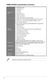
...2280 devices support(both SATA & PCIe mode) 1 x COM connector 1 x CPU Fan connector 1 x Chassis Fan connector (supports 3-pin DC & 4-pin PWM modes) 1 x Front panel audio connector 1 x 24-pin EATX power connector 1 x 8-pin EATX 12V power connector 1 x 2-pin Clear CMOS header 1 x System panel connector 1 x Speaker connector 1 x S/PDIF out connector 128 Mb Flash ROM, UEFI AMI BIOS, PnP, SM BIOS 3.1, ACPI 6.1, Multilanguage BIOS, ASUS EZ Flash 3, ASUS CrashFree BIOS 3, My Favorite, Last Modified log, F12 PrintScreen, ASUS DRAM SPD (Serial Presence Detect) memory information, F6 Qfan Control WOL by...
...2280 devices support(both SATA & PCIe mode) 1 x COM connector 1 x CPU Fan connector 1 x Chassis Fan connector (supports 3-pin DC & 4-pin PWM modes) 1 x Front panel audio connector 1 x 24-pin EATX power connector 1 x 8-pin EATX 12V power connector 1 x 2-pin Clear CMOS header 1 x System panel connector 1 x Speaker connector 1 x S/PDIF out connector 128 Mb Flash ROM, UEFI AMI BIOS, PnP, SM BIOS 3.1, ACPI 6.1, Multilanguage BIOS, ASUS EZ Flash 3, ASUS CrashFree BIOS 3, My Favorite, Last Modified log, F12 PrintScreen, ASUS DRAM SPD (Serial Presence Detect) memory information, F6 Qfan Control WOL by...
Users Manual English
Page 9
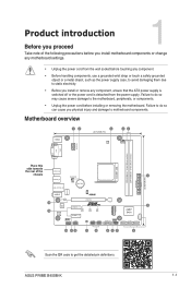
... before touching any component, ensure that the ATX power supply is switched off or the power cord is detached from the power supply. Failure to do so may cause severe damage to motherboard components. ASUS PRIME B450M-K 1-1 Product introduction Before you proceed 1 Take note of the U31G1_56 chassis CHA_FAN 1 U31G2_12 BATTERY LAN_U31G1_34 LANGuard 128Mb BIOS AUDIO M.2 (SOCKET3) SATA6G_4 16 15 Realtek 8111H Super I/O ALC 887 PCIEX16...
... before touching any component, ensure that the ATX power supply is switched off or the power cord is detached from the power supply. Failure to do so may cause severe damage to motherboard components. ASUS PRIME B450M-K 1-1 Product introduction Before you proceed 1 Take note of the U31G1_56 chassis CHA_FAN 1 U31G2_12 BATTERY LAN_U31G1_34 LANGuard 128Mb BIOS AUDIO M.2 (SOCKET3) SATA6G_4 16 15 Realtek 8111H Super I/O ALC 887 PCIEX16...

Users Manual English
Page 10
CPU and chassis fan connectors (4-pin CPU_FAN, 4-pin CHA_FAN) Connect the fan cables to the fan connectors. These are for AMD Ryzen™ 2nd Generation / Ryzen™ with more power-consuming devices or when you are designed to System memory. 1-2 Chapter 1: Product introduction AMD AM4 CPU socket This motherboard comes with an AMD AM4 socket designed for ATX power supply plugs. For more details, refer to install additional devices. Otherwise, the system will not boot up if the power is...
CPU and chassis fan connectors (4-pin CPU_FAN, 4-pin CHA_FAN) Connect the fan cables to the fan connectors. These are for AMD Ryzen™ 2nd Generation / Ryzen™ with more power-consuming devices or when you are designed to System memory. 1-2 Chapter 1: Product introduction AMD AM4 CPU socket This motherboard comes with an AMD AM4 socket designed for ATX power supply plugs. For more details, refer to install additional devices. Otherwise, the system will not boot up if the power is...
Users Manual English
Page 11
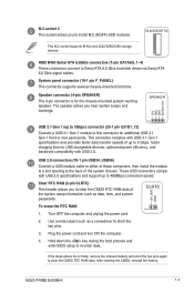
...system passwords. Plug the power cord and turn ON the computer. 4. After clearing the CMOS, reinstall the battery. System panel connector (10-1 pin F_PANEL) This connector supports several chassis-mounted functions. Clear RTC RAM (2-pin CLRTC) This header allows you to clear the CMOS RTC RAM data of these connectors, then install the module to Serial ATA 6.0 Gb/s hard disk drives via Serial ATA 6.0 Gb/s signal cables. ASUS PRIME B450M-K 1-3 M.2 socket 3 This socket allows you to 480Mbps connection speed. M.2(SOCKET3) This M.2 socket supports M Key and 2242/2260/2280 storage...
...system passwords. Plug the power cord and turn ON the computer. 4. After clearing the CMOS, reinstall the battery. System panel connector (10-1 pin F_PANEL) This connector supports several chassis-mounted functions. Clear RTC RAM (2-pin CLRTC) This header allows you to clear the CMOS RTC RAM data of these connectors, then install the module to Serial ATA 6.0 Gb/s hard disk drives via Serial ATA 6.0 Gb/s signal cables. ASUS PRIME B450M-K 1-3 M.2 socket 3 This socket allows you to 480Mbps connection speed. M.2(SOCKET3) This M.2 socket supports M Key and 2242/2260/2280 storage...
Users Manual English
Page 20
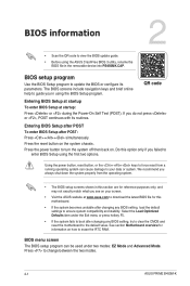
... Exit menu or press hotkey F5. • If the system fails to boot after changing any BIOS setting, load the default settings to enter BIOS Setup using the first two options. Using the power button, reset button, or the ++ keys to force reset from the operating system. • The BIOS setup screens shown in the removable device into PB450MK.CAP. Select the Load Optimized Defaults item under two modes: EZ Mode and Advanced Mode. QR code Entering BIOS Setup at startup To enter BIOS Setup at www.asus...
... Exit menu or press hotkey F5. • If the system fails to boot after changing any BIOS setting, load the default settings to enter BIOS Setup using the first two options. Using the power button, reset button, or the ++ keys to force reset from the operating system. • The BIOS setup screens shown in the removable device into PB450MK.CAP. Select the Load Optimized Defaults item under two modes: EZ Mode and Advanced Mode. QR code Entering BIOS Setup at startup To enter BIOS Setup at www.asus...


