
Motherboard Pin Definition.English
Page 5
... in reduced power mode). (Default) • The USB device wake-up feature requires a power supply that can supply at least 1A on the keyboard. Display panel VCC power selector (VCC_PWR_SEL) Pins 1 (Default) 2 3 Setting 3V 5V 12V 7. 3. USB device wake-up (3-pin USBPWF) Set these jumpers to +5V to CPU, ...DRAM in slow +5V +5VSB refresh, power supply in the BIOS. 12 23 KB_USBPWB +5V +5VSB (Default) 5. Display panel backlight power selector (3-pin BLKT_PWR_SEL) BLKT_PWR_SEL 12 23 Pins 1-2 (Default) 2-3 Setting 12V 19V 12V 19V (Default) 6.
... in reduced power mode). (Default) • The USB device wake-up feature requires a power supply that can supply at least 1A on the keyboard. Display panel VCC power selector (VCC_PWR_SEL) Pins 1 (Default) 2 3 Setting 3V 5V 12V 7. 3. USB device wake-up (3-pin USBPWF) Set these jumpers to +5V to CPU, ...DRAM in slow +5V +5VSB refresh, power supply in the BIOS. 12 23 KB_USBPWB +5V +5VSB (Default) 5. Display panel backlight power selector (3-pin BLKT_PWR_SEL) BLKT_PWR_SEL 12 23 Pins 1-2 (Default) 2-3 Setting 12V 19V 12V 19V (Default) 6.
Motherboard Pin Definition.English
Page 6
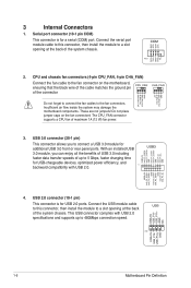
... module to 5 Gbps, faster charging time for a serial (COM) port. Serial port connector (10-1 pin COM) This connector is for additional USB 3.0 front or rear panel ports. The CPU_FAN connector supports a CPU fan of the connector CHA_FAN CPU FAN PWM CPU FAN IN CPU FAN PWR GND +5V CHA FAN IN...
... module to 5 Gbps, faster charging time for a serial (COM) port. Serial port connector (10-1 pin COM) This connector is for additional USB 3.0 front or rear panel ports. The CPU_FAN connector supports a CPU fan of the connector CHA_FAN CPU FAN PWM CPU FAN IN CPU FAN PWR GND +5V CHA FAN IN...
Motherboard Pin Definition.English
Page 8
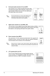
... O_LPT_XPD2_R O_LPT_XPD3_R O_LPT_XPD4_R O_LPT_XPD5_R O_LPT_XPD6_R O_LPT_XPD7_R O_LPT_ACK#_R O_LPT_BUSY_R O_LPT_PE_R O_LPT_SLCT_R 1-8 Motherboard Pin Definition Connect one end of the front panel audio I /O module that supports the PIN 1 DirectKey feature. Refer to the technical documentation that came with the button...supports devices such as IEEE 1284, which is for an additional Sony/Philips Digital Interface (S/PDIF) SPDIF_OUT port. 8. Front panel audio connector (10-1 pin AAFP) This connector is the parallel port interface on the motherboard. Connect the S/PDIF Out module...
... O_LPT_XPD2_R O_LPT_XPD3_R O_LPT_XPD4_R O_LPT_XPD5_R O_LPT_XPD6_R O_LPT_XPD7_R O_LPT_ACK#_R O_LPT_BUSY_R O_LPT_PE_R O_LPT_SLCT_R 1-8 Motherboard Pin Definition Connect one end of the front panel audio I /O module that supports the PIN 1 DirectKey feature. Refer to the technical documentation that came with the button...supports devices such as IEEE 1284, which is for an additional Sony/Philips Digital Interface (S/PDIF) SPDIF_OUT port. 8. Front panel audio connector (10-1 pin AAFP) This connector is the parallel port interface on the motherboard. Connect the S/PDIF Out module...
Motherboard Pin Definition.English
Page 10
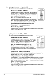
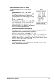
... to this connector. Pressing the power button turns the system on the BIOS settings. Connect the HDD Activity LED cable to this connector. 16. System panel connector (10-1 pin F_PANEL) This connector supports several chassis-mounted functions. • System power LED (2-pin PWR_LED) F_PANEL +PWR_LED- System...
... to this connector. Pressing the power button turns the system on the BIOS settings. Connect the HDD Activity LED cable to this connector. 16. System panel connector (10-1 pin F_PANEL) This connector supports several chassis-mounted functions. • System power LED (2-pin PWR_LED) F_PANEL +PWR_LED- System...
Motherboard Pin Definition.English
Page 11
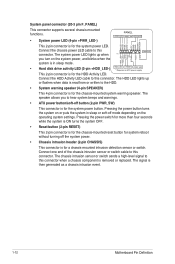
...; Hard disk drive activity LED (2-pin +HDD_LED-) This 2-pin connector is for the system power button. System panel connector (20-5 pin PANEL) This connector supports several chassis-mounted functions. • System power LED (4-pin +PWR_LED-) PANEL +PWR_LED- Connect the HDD Activity LED cable to this connector. The HDD LED lights up when you...
...; Hard disk drive activity LED (2-pin +HDD_LED-) This 2-pin connector is for the system power button. System panel connector (20-5 pin PANEL) This connector supports several chassis-mounted functions. • System power LED (4-pin +PWR_LED-) PANEL +PWR_LED- Connect the HDD Activity LED cable to this connector. The HDD LED lights up when you...
Motherboard Pin Definition.English
Page 12
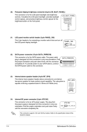
... the HDD. • System warning speaker (4-pin SPEAKER) This 4-pin connector is removed or replaced. System panel connector (20-3 pin F_PANEL) This connector supports several chassis-mounted functions. • System power LED (4-pin +PWR_LED-) PANEL +PWR_LED- The chassis intrusion sensor or switch sends a high-level signal to this connector when a chassis component...
... the HDD. • System warning speaker (4-pin SPEAKER) This 4-pin connector is removed or replaced. System panel connector (20-3 pin F_PANEL) This connector supports several chassis-mounted functions. • System power LED (4-pin +PWR_LED-) PANEL +PWR_LED- The chassis intrusion sensor or switch sends a high-level signal to this connector when a chassis component...
Motherboard Pin Definition.English
Page 14
...(4-pin INT_SPK) The internal mono speaker header allows connection to an internal, low-power speaker for the brightness button on the front panel. The plug from the power supply is designed to fit this connector in only one orientation. ATX19V GND PIN 1 DC_JACK_IN This ...your SATA device, connect the SATA power cable to the specification sheet of 4 Ohms at 3 Watts (rms). The subsystem is for the LCD panel backlight and brightness controls. Front_L+ Front_R+ Front_R- Internal DC power connector (2-pin ATX19V) This connector is designed to fit this connector. +12V...
...(4-pin INT_SPK) The internal mono speaker header allows connection to an internal, low-power speaker for the brightness button on the front panel. The plug from the power supply is designed to fit this connector in only one orientation. ATX19V GND PIN 1 DC_JACK_IN This ...your SATA device, connect the SATA power cable to the specification sheet of 4 Ohms at 3 Watts (rms). The subsystem is for the LCD panel backlight and brightness controls. Front_L+ Front_R+ Front_R- Internal DC power connector (2-pin ATX19V) This connector is designed to fit this connector. +12V...
E12583 BIOS Update ManualEnglish
Page 10
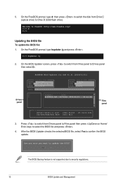
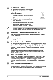
On the FreeDOS prompt, type bupdater /g and press . 5. Drives panel ASUSTeK BIOS Updater for DOS V1.31 [2014/01/01] Current ROM BOARD: B150-PLUS VER: 0303 (H ...End] Move [Tab] Switch [Esc] Exit [V] Drive Info Files panel 3. On the BIOS Updater screen, press to switch from Files panel to update the BIOS? Are you sure you want to Drives panel then select D:. Welcome to select the BIOS file and press ....D:/> bupdater /g 2. On the FreeDOS prompt, type d: then press to switch the disk from Drives panel to Files panel then press keys to FreeDOS (http://www.freedos.org)!
On the FreeDOS prompt, type bupdater /g and press . 5. Drives panel ASUSTeK BIOS Updater for DOS V1.31 [2014/01/01] Current ROM BOARD: B150-PLUS VER: 0303 (H ...End] Move [Tab] Switch [Esc] Exit [V] Drive Info Files panel 3. On the BIOS Updater screen, press to switch from Files panel to update the BIOS? Are you sure you want to Drives panel then select D:. Welcome to select the BIOS file and press ....D:/> bupdater /g 2. On the FreeDOS prompt, type d: then press to switch the disk from Drives panel to Files panel then press keys to FreeDOS (http://www.freedos.org)!
PRIME B250M-A Users manual ENGLISH
Page 7
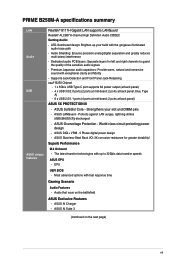
... left and right channels to 32Gb/s data transfer speeds ASUS EPU - Superb Performance M.2 Onboard - The latest transfer technologies with the gorgeous illuminated audio trace path - PRIME B250M-A specifications summary LAN Audio USB ASUS unique features Realtek® 8111H Gigabit LAN supports LANGuard .../s USB Type C port supports 3A power output (at back panel) - 4 x USB 3.0/2.0 ports (2 ports at mid-board; 2 ports at back panel, blue, Type A) - 6 x USB 2.0/1.1 ports (4 ports at mid-board; 2 ports at back panel) ASUS 5X PROTECTION III - Strengthens your build with up to guard ...
... left and right channels to 32Gb/s data transfer speeds ASUS EPU - Superb Performance M.2 Onboard - The latest transfer technologies with the gorgeous illuminated audio trace path - PRIME B250M-A specifications summary LAN Audio USB ASUS unique features Realtek® 8111H Gigabit LAN supports LANGuard .../s USB Type C port supports 3A power output (at back panel) - 4 x USB 3.0/2.0 ports (2 ports at mid-board; 2 ports at back panel, blue, Type A) - 6 x USB 2.0/1.1 ports (4 ports at mid-board; 2 ports at back panel) ASUS 5X PROTECTION III - Strengthens your build with up to guard ...
PRIME B250M-A Users manual ENGLISH
Page 8
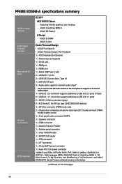
... Control, F3 My Favorites, Last Modified log, F12 PrintScreen, and ASUS DRAM SPD (Serial Presence Detect) memory information (continued on the next page) viii Featuring friendly graphics user interface - ASUS Q-Slot Quiet Thermal Design - PRIME B250M-A specifications summary ASUS unique features ASUS Quiet Thermal Solution Rear panel I/O ports Internal connectors BIOS features EZ DIY UEFI BIOS EZ...
... Control, F3 My Favorites, Last Modified log, F12 PrintScreen, and ASUS DRAM SPD (Serial Presence Detect) memory information (continued on the next page) viii Featuring friendly graphics user interface - ASUS Q-Slot Quiet Thermal Design - PRIME B250M-A specifications summary ASUS unique features ASUS Quiet Thermal Solution Rear panel I/O ports Internal connectors BIOS features EZ DIY UEFI BIOS EZ...

PRIME B250M-A Users manual ENGLISH
Page 11
...CPU into this surface mount LGA1151 socket, which is for your system, refer to the fan connectors on the fan connectors! System panel connector (10-1 pin F_PANEL) This connector supports several chassis-mounted functions. CPU and chassis fan connectors (4-pin CPU_FAN, 4-pin CHA_FAN...pin SPEAKER) This 4-pin connector is designed for details. For more details, refer to Central Processing Unit (CPU). Chapter 1: Product introduction 1-2 asus.com/PowerSupplyCalculator/PSCalculator.aspx?SLanguage=en-us for 7th / 6th Generation Intel® Core™ i7 / i5 / i3, Pentium®, and...
...CPU into this surface mount LGA1151 socket, which is for your system, refer to the fan connectors on the fan connectors! System panel connector (10-1 pin F_PANEL) This connector supports several chassis-mounted functions. CPU and chassis fan connectors (4-pin CPU_FAN, 4-pin CHA_FAN...pin SPEAKER) This 4-pin connector is designed for details. For more details, refer to Central Processing Unit (CPU). Chapter 1: Product introduction 1-2 asus.com/PowerSupplyCalculator/PSCalculator.aspx?SLanguage=en-us for 7th / 6th Generation Intel® Core™ i7 / i5 / i3, Pentium®, and...
PRIME B250M-A Users manual ENGLISH
Page 12
... rear panel ports. USB 2.0 connectors (10-1 pin USB910, USB1112) Connect the USB module cable to any of the system chassis. Turn OFF the computer and unplug the power cord. 2. By default, the pin labeled "Chassis Signal" and "Ground" are shorted with USB 2.0 specifications and support up to 480Mbps connection speed. 1-3 ASUS PRIME B250M-A USB...
... rear panel ports. USB 2.0 connectors (10-1 pin USB910, USB1112) Connect the USB module cable to any of the system chassis. Turn OFF the computer and unplug the power cord. 2. By default, the pin labeled "Chassis Signal" and "Ground" are shorted with USB 2.0 specifications and support up to 480Mbps connection speed. 1-3 ASUS PRIME B250M-A USB...

PRIME B250M-A Users manual ENGLISH
Page 13
...SCSI cards, and other cards that comply with the PCI Express specifications. By default, this connector, set the Front Panel Type item in the BIOS setup to [AC97]. Serial port connector (10-1 pin COM) This connector is for a chassis-mounted front...Platform Module (TPM) system, which is the parallel port interface on IBM PCcompatible computers. Chapter 1: Product introduction 1-4 Connect one end of the front panel audio I /O module that supports PCI Express 3.0/2.0 x16 graphic cards complying with the PCI Express specifications PCI Express 3.0/2.0 x16 slot This motherboard has ...
...SCSI cards, and other cards that comply with the PCI Express specifications. By default, this connector, set the Front Panel Type item in the BIOS setup to [AC97]. Serial port connector (10-1 pin COM) This connector is for a chassis-mounted front...Platform Module (TPM) system, which is the parallel port interface on IBM PCcompatible computers. Chapter 1: Product introduction 1-4 Connect one end of the front panel audio I /O module that supports PCI Express 3.0/2.0 x16 graphic cards complying with the PCI Express specifications PCI Express 3.0/2.0 x16 slot This motherboard has ...

PRIME B250M-A Users manual ENGLISH
Page 15
... for a VGA monitor or other audio sources. 5. This port connects to the tape, CD, DVD player, or other VGA-compatible devices. 3. Chapter 1: Product introduction 1-6 Rear panel connectors 1 2 3 45 12 11 10 9 8 7 6 1. This port is for the function of this port becomes Front Speaker Out. 6. LAN (RJ-45) port. This port connects...
... for a VGA monitor or other audio sources. 5. This port connects to the tape, CD, DVD player, or other VGA-compatible devices. 3. Chapter 1: Product introduction 1-6 Rear panel connectors 1 2 3 45 12 11 10 9 8 7 6 1. This port is for the function of this port becomes Front Speaker Out. 6. LAN (RJ-45) port. This port connects...
PRIME B250M-A Users manual ENGLISH
Page 16
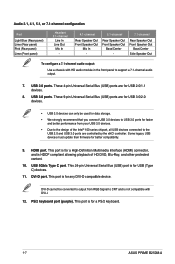
... USB 3.0 devices can only be converted to output from your USB 3.0 devices. • Due to USB 3.0 ports for a PS/2 keyboard. 1-7 ASUS PRIME B250M-A This port is for any DVI-D compatible device. HDMI port. This 24-pin Universal Serial Bus (USB) port is for USB (Type C) devices....Bus (USB) ports are controlled by the xHCI controller. Audio 2.1, 4.1, 5.1, or 7.1-channel configuration Port Light Blue (Rear panel) Lime (Rear panel) Pink (Rear panel) Lime (Front panel) Headset 2.1-channel Line In Line Out Mic In - 4.1-channel Rear Speaker Out Front Speaker Out Mic In - 5.1-channel ...
... USB 3.0 devices can only be converted to output from your USB 3.0 devices. • Due to USB 3.0 ports for a PS/2 keyboard. 1-7 ASUS PRIME B250M-A This port is for any DVI-D compatible device. HDMI port. This 24-pin Universal Serial Bus (USB) port is for USB (Type C) devices....Bus (USB) ports are controlled by the xHCI controller. Audio 2.1, 4.1, 5.1, or 7.1-channel configuration Port Light Blue (Rear panel) Lime (Rear panel) Pink (Rear panel) Lime (Front panel) Headset 2.1-channel Line In Line Out Mic In - 4.1-channel Rear Speaker Out Front Speaker Out Mic In - 5.1-channel ...


