
User Manual
Page 3
Contents Contents...iii Notices...vii Safety information ix About this guide x P9X79 WS specifications summary xii Chapter 1: Product introduction 1.1 Welcome 1-1 1.2 Package contents 1-1 1.3 Special features 1-2 1.3.1 Product highlights 1-2 1.3.2 ASUS Workstation Exclusive Features 1-3 1.3.3 ASUS features 1-4 1.3.4 Other special features 1-8 Chapter 2: Hardware information 2.1 Before you proceed 2-1 2.2 Motherboard overview ... installation 2-38 2.3.4 DIMM installation 2-39 2.3.5 Motherboard installation 2-40 2.3.6 ATX Power connection 2-42 2.3.7 SATA device connection 2-43 iii
Contents Contents...iii Notices...vii Safety information ix About this guide x P9X79 WS specifications summary xii Chapter 1: Product introduction 1.1 Welcome 1-1 1.2 Package contents 1-1 1.3 Special features 1-2 1.3.1 Product highlights 1-2 1.3.2 ASUS Workstation Exclusive Features 1-3 1.3.3 ASUS features 1-4 1.3.4 Other special features 1-8 Chapter 2: Hardware information 2.1 Before you proceed 2-1 2.2 Motherboard overview ... installation 2-38 2.3.4 DIMM installation 2-39 2.3.5 Motherboard installation 2-40 2.3.6 ATX Power connection 2-42 2.3.7 SATA device connection 2-43 iii
User Manual
Page 29
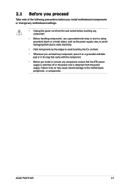
ASUS P9X79 WS 2-1 Failure to do so may cause severe damage to avoid touching the ICs on them. • Whenever you uninstall any component, place it on a grounded ... you install motherboard components or change any motherboard settings. • Unplug the power cord from the wall socket before touching any component, ensure that the ATX power supply is switched off or the power cord is detached from the power supply.
ASUS P9X79 WS 2-1 Failure to do so may cause severe damage to avoid touching the ICs on them. • Whenever you uninstall any component, place it on a grounded ... you install motherboard components or change any motherboard settings. • Unplug the power cord from the wall socket before touching any component, ensure that the ATX power supply is switched off or the power cord is detached from the power supply.
User Manual
Page 31
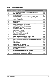
...2-13 2-10 2-22 2-23 2-24 2-25 2-14 2-22 2-34 2-27 2-12 2-26 2-25 2-30 2-21 2-10 2-28 2-28 2-30 ASUS P9X79 WS 2-3 Clear RTC RAM (3-pin CLRTC) 21. Reset switch 17. switch 7 E�P�U�S�w�itc�h 8. 2.2.2 Layout contents Connectors/Jumpers/Switches...65533;in ��C�H��A�F�A�N�_�S��E�L�) 14. ATX P��o�w�e�r��c�o�n�n�e�c�t�o�rs��(&#...
...2-13 2-10 2-22 2-23 2-24 2-25 2-14 2-22 2-34 2-27 2-12 2-26 2-25 2-30 2-21 2-10 2-28 2-28 2-30 ASUS P9X79 WS 2-3 Clear RTC RAM (3-pin CLRTC) 21. Reset switch 17. switch 7 E�P�U�S�w�itc�h 8. 2.2.2 Layout contents Connectors/Jumpers/Switches...65533;in ��C�H��A�F�A�N�_�S��E�L�) 14. ATX P��o�w�e�r��c�o�n�n�e�c�t�o�rs��(&#...

User Manual
Page 60
...the proper orientation and push down firmly until the connectors completely fit. • For a fully configured system, we recommend that complies with ATX 12 V Specification 2.0 (or later version) and provides a minimum power of a PSU with a higher power output is inadequate. •...; If you are designed to the Recommended Power Supply Wattage Calculator at http://support.asus.com/PowerSupplyCalculator/PSCalculator. aspx?SLanguage=en-us for ATX power supply plugs. ATX power connectors (24-pin EATXPWR; 8-pin EATX12V) These connectors are for details. • If...
...the proper orientation and push down firmly until the connectors completely fit. • For a fully configured system, we recommend that complies with ATX 12 V Specification 2.0 (or later version) and provides a minimum power of a PSU with a higher power output is inadequate. •...; If you are designed to the Recommended Power Supply Wattage Calculator at http://support.asus.com/PowerSupplyCalculator/PSCalculator. aspx?SLanguage=en-us for ATX power supply plugs. ATX power connectors (24-pin EATXPWR; 8-pin EATX12V) These connectors are for details. • If...

User Manual
Page 62
... speaker (4-pin SPEAKER) This 4-pin connector is for the system power button. Connect the HDD Activity LED cable to hear system beeps and warnings. • ATX power button/soft-off button (2-pin PWRSW) This connector is for the chassis-mounted system warning speaker. System panel connector (20-8 pin PANEL) This connector...
... speaker (4-pin SPEAKER) This 4-pin connector is for the system power button. Connect the HDD Activity LED cable to hear system beeps and warnings. • ATX power button/soft-off button (2-pin PWRSW) This connector is for the chassis-mounted system warning speaker. System panel connector (20-8 pin PANEL) This connector...

User Manual
Page 70
2.3.6 1 ATX Power connection 2 OR 2-42 Chapter 2: Hardware information
2.3.6 1 ATX Power connection 2 OR 2-42 Chapter 2: Hardware information

User Manual
Page 78
.... 4. After applying power, the system power LED on the screen. If your retailer for the first time 1. If you press the ATX power button. Be sure that is equipped with ATX power supplies, the system LED lights up or change from the time you turned on the power, the system may have...
.... 4. After applying power, the system power LED on the screen. If your retailer for the first time 1. If you press the ATX power button. Be sure that is equipped with ATX power supplies, the system LED lights up or change from the time you turned on the power, the system may have...

