
User Guide
Page 16
This chapter contains the following sections: 1.1 Welcome!...1-3 1.2 Package contents 1-3 1.3 Serial number label 1-4 1.4 Special features 1-4 ASUS P9D-X Chapter summary 1 This chapter describes the motherboard features and the new technologies it supports.
This chapter contains the following sections: 1.1 Welcome!...1-3 1.2 Package contents 1-3 1.3 Serial number label 1-4 1.4 Special features 1-4 ASUS P9D-X Chapter summary 1 This chapter describes the motherboard features and the new technologies it supports.
User Guide
Page 17
... cable Cables SATA 3G cable SATA 6G cable Application CD Support CD ASWM Enterprise SDVD Documentation Motherboard User Guide Accessory Metal Plate for buying an ASUS® P9D-X motherboard! The motherboard delivers a host of the above items is damaged or missing, contact your retailer. Before you for LGA1150 Packaging Qty. 1 1 4 2 1 1 1 1 1 pc per... Standard Bulk Pack 1 ---1 1 1 1 10 pcs per carton If any of new features and latest technologies, making it , check the items in the long line of ASUS quality motherboards! 1.1 Welcome! ASUS P9D-X 1-3
... cable Cables SATA 3G cable SATA 6G cable Application CD Support CD ASWM Enterprise SDVD Documentation Motherboard User Guide Accessory Metal Plate for buying an ASUS® P9D-X motherboard! The motherboard delivers a host of the above items is damaged or missing, contact your retailer. Before you for LGA1150 Packaging Qty. 1 1 4 2 1 1 1 1 1 pc per... Standard Bulk Pack 1 ---1 1 1 1 10 pcs per carton If any of new features and latest technologies, making it , check the items in the long line of ASUS quality motherboards! 1.1 Welcome! ASUS P9D-X 1-3
User Guide
Page 19
... the CPU loading and system speed or power requirement. The Serial ATA II specification provides twice the bandwidth of up to 6Gbps data transfer rates. ASUS P9D-X 1-5 Serial ATA II technology The motherboard supports the Serial ATA II 3 Gb/s technology through the Serial ATA interface and Intel® C222 chipset. Enhanced Intel...
... the CPU loading and system speed or power requirement. The Serial ATA II specification provides twice the bandwidth of up to 6Gbps data transfer rates. ASUS P9D-X 1-5 Serial ATA II technology The motherboard supports the Serial ATA II 3 Gb/s technology through the Serial ATA interface and Intel® C222 chipset. Enhanced Intel...
User Guide
Page 23
... Take note of the following precautions before you install motherboard components or change any motherboard settings. • Unplug the power cord from the power supply. ASUS P9D-X 2-3 Failure to do so may cause severe damage to avoid touching the ICs on them. • Whenever you uninstall any component, place it on a grounded...
... Take note of the following precautions before you install motherboard components or change any motherboard settings. • Unplug the power cord from the power supply. ASUS P9D-X 2-3 Failure to do so may cause severe damage to avoid touching the ICs on them. • Whenever you uninstall any component, place it on a grounded...
User Guide
Page 25
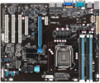
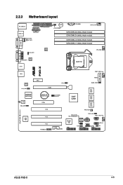
2.2.3 Motherboard layout ASUS P9D-X 2-5
2.2.3 Motherboard layout ASUS P9D-X 2-5
User Guide
Page 29
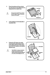
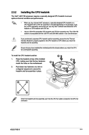
... only one orientation. DO NOT force the CPU into the socket to the socket's alignment keys. Gold triangle mark Alignment key CPU notches Alignment key ASUS P9D-X 2-9 Press the load lever with your thumb (A), then move it is on the socket and damaging the CPU. Doing so may bend the pins of...
... only one orientation. DO NOT force the CPU into the socket to the socket's alignment keys. Gold triangle mark Alignment key CPU notches Alignment key ASUS P9D-X 2-9 Press the load lever with your thumb (A), then move it is on the socket and damaging the CPU. Doing so may bend the pins of...
User Guide
Page 31
... chassis before you buy a boxed Intel® processor, a specially designed CPU heatsink or a CPU heatsink with the LGA775 and LGA1366 sockets in size and dimension. ASUS P9D-X 2-11 Ensure that you install the CPU fan and heatsink assembly. Push down two fasteners at a time in a diagonal sequence to ensure optimum thermal condition...
... chassis before you buy a boxed Intel® processor, a specially designed CPU heatsink or a CPU heatsink with the LGA775 and LGA1366 sockets in size and dimension. ASUS P9D-X 2-11 Ensure that you install the CPU fan and heatsink assembly. Push down two fasteners at a time in a diagonal sequence to ensure optimum thermal condition...
User Guide
Page 33
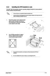
... heatsink is not skewed or tilted, otherwise the CPU will overheat. 2. Use a Phillips screwdriver to tighten the four heatsink screws using the recommended sequence below. ASUS P9D-X 2-13
... heatsink is not skewed or tilted, otherwise the CPU will overheat. 2. Use a Phillips screwdriver to tighten the four heatsink screws using the recommended sequence below. ASUS P9D-X 2-13
User Guide
Page 35
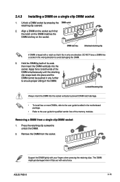
... from the socket. 1 Support the DIMM lightly with your fingers when pressing the retaining clips. Press the retaining clip outward to avoid damaging the DIMM. 3. ASUS P9D-X 2-15 DO NOT force a DIMM into the socket vertically to prevent DIMM notch damage. • To install two or more DIMMs, refer to the user...
... from the socket. 1 Support the DIMM lightly with your fingers when pressing the retaining clips. Press the retaining clip outward to avoid damaging the DIMM. 3. ASUS P9D-X 2-15 DO NOT force a DIMM into the socket vertically to prevent DIMM notch damage. • To install two or more DIMMs, refer to the user...
User Guide
Page 37
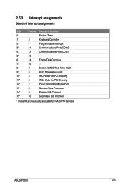
ASUS P9D-X 2-17 2.5.3 Interrupt assignments Standard Interrupt assignments IRQ Priority Standard function 0 1 System Timer 1 2 Keyboard Controller 2 - Programmable Interrupt 3* 11 Communications Port (COM2) 4* 12 Communications Port (COM1) 5* 13 -- 6 ...
ASUS P9D-X 2-17 2.5.3 Interrupt assignments Standard Interrupt assignments IRQ Priority Standard function 0 1 System Timer 1 2 Keyboard Controller 2 - Programmable Interrupt 3* 11 Communications Port (COM2) 4* 12 Communications Port (COM1) 5* 13 -- 6 ...
User Guide
Page 39
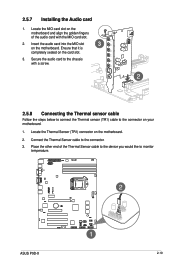
.... 2. Locate the Thermal Sensor (TR1) connector on the motherboard. Ensure that it is completely seated on your motherboard. 1. Secure the audio card to the connector. 3. ASUS P9D-X 2-19
.... 2. Locate the Thermal Sensor (TR1) connector on the motherboard. Ensure that it is completely seated on your motherboard. 1. Secure the audio card to the connector. 3. ASUS P9D-X 2-19
User Guide
Page 41
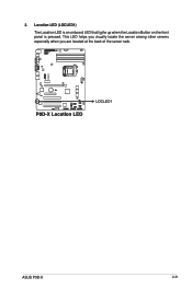
ASUS P9D-X 2-21 3. Location LED (LOCLED1) The Location LED is an onboard LED that ligths up when the Location Button on the front panel is pressed. This LED helps you visually locate the server among other servers especially when you are located at the back of the server rack.
ASUS P9D-X 2-21 3. Location LED (LOCLED1) The Location LED is an onboard LED that ligths up when the Location Button on the front panel is pressed. This LED helps you visually locate the server among other servers especially when you are located at the back of the server rack.
User Guide
Page 43
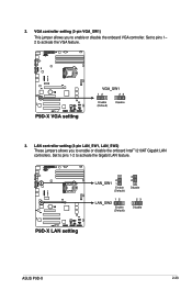
Set to pins 1- 2 to enable or disable the onboard Intel® I210AT Gigabit LAN controllers. 2. LAN controller setting (3-pin LAN_SW1, LAN_SW2) These jumpers allows you to activate the Gigabit LAN feature. ASUS P9D-X 2-23 Set to pins 1-2 to enable or disable the onboard VGA controller. VGA controller setting (3-pin VGA_SW1) This jumper allows you to activate the VGA feature. 3.
Set to pins 1- 2 to enable or disable the onboard Intel® I210AT Gigabit LAN controllers. 2. LAN controller setting (3-pin LAN_SW1, LAN_SW2) These jumpers allows you to activate the Gigabit LAN feature. ASUS P9D-X 2-23 Set to pins 1-2 to enable or disable the onboard VGA controller. VGA controller setting (3-pin VGA_SW1) This jumper allows you to activate the VGA feature. 3.

User Guide
Page 45
... No link OFF 10 Mbps connection GREEN Linked ORANGE 100 Mbps connection BLINKING Data activity GREEN 1 Gbps connection ACT/LINK SPEED LED LED LAN port ASUS P9D-X 2-25
... No link OFF 10 Mbps connection GREEN Linked ORANGE 100 Mbps connection BLINKING Data activity GREEN 1 Gbps connection ACT/LINK SPEED LED LED LAN port ASUS P9D-X 2-25
User Guide
Page 47
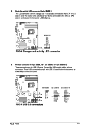
Connect the USB module cables to light up to the SATA or SAS add-on card cable connected to 480 Mbps connection speed. The read or write activities of any device connected to the SATA or SAS add-on card causes the front panel LED to these connectors. USB 2.0 connector (A-Type USB9 , 10-1 pin USB78, 10-1 pin USB1011) These connectors are for the storage add-on card. These USB connectors comply with USB 2.0 specification that supports up . 3. ASUS P9D-X 2-27 2. Hard disk activity LED connector (4-pin HDLED1) This LED connector is for USB 2.0 ports.
Connect the USB module cables to light up to the SATA or SAS add-on card cable connected to 480 Mbps connection speed. The read or write activities of any device connected to the SATA or SAS add-on card causes the front panel LED to these connectors. USB 2.0 connector (A-Type USB9 , 10-1 pin USB78, 10-1 pin USB1011) These connectors are for the storage add-on card. These USB connectors comply with USB 2.0 specification that supports up . 3. ASUS P9D-X 2-27 2. Hard disk activity LED connector (4-pin HDLED1) This LED connector is for USB 2.0 ports.
User Guide
Page 49
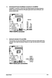
ASUS P9D-X 2-29 Connect the serial port module cable to the connector, then install the serial port module to an open slot at the back of the system chassis. Serial General Purpose Input/Output connector (6-1 pin SGPIO1) The SGPIO 1 connector is for the Intel Rapid Storage Technology Enterprise SGPIO interface that controls the LED pattern generation, device information, and general purpose data. 7. Serial port connector (10-1 pin COM2) The connector is used for the serial COM port. 6.
ASUS P9D-X 2-29 Connect the serial port module cable to the connector, then install the serial port module to an open slot at the back of the system chassis. Serial General Purpose Input/Output connector (6-1 pin SGPIO1) The SGPIO 1 connector is for the Intel Rapid Storage Technology Enterprise SGPIO interface that controls the LED pattern generation, device information, and general purpose data. 7. Serial port connector (10-1 pin COM2) The connector is used for the serial COM port. 6.
User Guide
Page 51
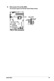
VGA connector (16-1 pin VGA_HDR1) This connector supports the VGA High Dynamic-Range interface. 10. ASUS P9D-X 2-31
VGA connector (16-1 pin VGA_HDR1) This connector supports the VGA High Dynamic-Range interface. 10. ASUS P9D-X 2-31
User Guide
Page 53
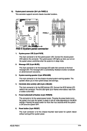
...) This 2-pin connector is in sleep or soft-off button (2-pin PWRSW) This connector is read from or written to hear system beeps and warnings. 4. ASUS P9D-X 2-33 System panel connector (20-1 pin PANEL1) This connector supports several chassis-mounted functions. 1. System power LED (3-pin PLED) This 3-pin connector is for the...
...) This 2-pin connector is in sleep or soft-off button (2-pin PWRSW) This connector is read from or written to hear system beeps and warnings. 4. ASUS P9D-X 2-33 System panel connector (20-1 pin PANEL1) This connector supports several chassis-mounted functions. 1. System power LED (3-pin PLED) This 3-pin connector is for the...

User Guide
Page 56
Chapter summary 3 This chapter describes the power up sequence, and ways of shutting down the system.This chapter contains the following sections: 3.1 Starting up for the first time 3-3 3.2 Powering off the computer 3-4 ASUS P9D-X
Chapter summary 3 This chapter describes the power up sequence, and ways of shutting down the system.This chapter contains the following sections: 3.1 Starting up for the first time 3-3 3.2 Powering off the computer 3-4 ASUS P9D-X

User Guide
Page 57
... the key to the power connector at the back of the system chassis. 4. At power on the system front panel case lights up for assistance. 7. ASUS P9D-X 3-3 Follow the instructions in the following order: a. Be sure that is equipped with the last device on the devices in Chapter 4. System power 6.
... the key to the power connector at the back of the system chassis. 4. At power on the system front panel case lights up for assistance. 7. ASUS P9D-X 3-3 Follow the instructions in the following order: a. Be sure that is equipped with the last device on the devices in Chapter 4. System power 6.


