User Guide
Page 3
... 1-3 1.3 Serial number label 1-4 1.4 Special features 1-4 1.4.1 Product highlights 1-4 1.4.2 Innovative ASUS features 1-6 Chapter 2: Hardware Information 2.1 Before you proceed 2-3 2.2 Motherboard overview 2-4 2.2.1 Placement direction 2-4 2.2.2 Screw holes 2-4 2.2.3 Motherboard layout 2-5 2.2.4 Layout contents 2-6 2.3 Central Processing Unit (CPU 2-8 2.3.1 Installing the CPU 2-8 2.3.2 Installing the CPU heatsink 2-11 2.3.3 Uninstalling the CPU heatsink and fan 2-12 2.3.4 Installing the CPU heatsink in rack 2-13 2.4 System memory 2-14 2.4.1 Overview...
... 1-3 1.3 Serial number label 1-4 1.4 Special features 1-4 1.4.1 Product highlights 1-4 1.4.2 Innovative ASUS features 1-6 Chapter 2: Hardware Information 2.1 Before you proceed 2-3 2.2 Motherboard overview 2-4 2.2.1 Placement direction 2-4 2.2.2 Screw holes 2-4 2.2.3 Motherboard layout 2-5 2.2.4 Layout contents 2-6 2.3 Central Processing Unit (CPU 2-8 2.3.1 Installing the CPU 2-8 2.3.2 Installing the CPU heatsink 2-11 2.3.3 Uninstalling the CPU heatsink and fan 2-12 2.3.4 Installing the CPU heatsink in rack 2-13 2.4 System memory 2-14 2.4.1 Overview...

User Guide
Page 5
Contents 4.3 Main menu 4-10 4.3.1 System Date 4-10 4.3.2 System Time 4-10 4.4 Advanced menu 4-11 4.4.1 CPU Configuration 4-12 4.4.2 PCH-IO Configuration 4-15 4.4.3 SATA Configuration 4-16 4.4.4 System Agent (SA) Configuration 4-17 4.4.5 PCI Subsystem Settings 4-19 4.4.6 USB Configuration 4-21 4.4.7 TPM 4-22 4.4.8 ACPI Settings 4-...
Contents 4.3 Main menu 4-10 4.3.1 System Date 4-10 4.3.2 System Time 4-10 4.4 Advanced menu 4-11 4.4.1 CPU Configuration 4-12 4.4.2 PCH-IO Configuration 4-15 4.4.3 SATA Configuration 4-16 4.4.4 System Agent (SA) Configuration 4-17 4.4.5 PCI Subsystem Settings 4-19 4.4.6 USB Configuration 4-21 4.4.7 TPM 4-22 4.4.8 ACPI Settings 4-...

User Guide
Page 13
... power connector 4-pin power connector 2 x USB 2.0 pin header (up to 4 devices) 1 x USB 2.0 connector (Type A USB socket) 5 x 4 pin headers 1 2 1 1 1 2 x USB 3.0 2 x USB 2.0 1 2 x GbE LAN 1 Software ASWM Enterprise CPU Temperature FAN RPM Operation temperature: 10oC - 35oC (50oF - 95oF) Non operation temperature: -40oC - 70oC (-40oF - 158oF) Non operation humidity: 20% - 90% (Non condensing) Specifications are...
... power connector 4-pin power connector 2 x USB 2.0 pin header (up to 4 devices) 1 x USB 2.0 connector (Type A USB socket) 5 x 4 pin headers 1 2 1 1 1 2 x USB 3.0 2 x USB 2.0 1 2 x GbE LAN 1 Software ASWM Enterprise CPU Temperature FAN RPM Operation temperature: 10oC - 35oC (50oF - 95oF) Non operation temperature: -40oC - 70oC (-40oF - 158oF) Non operation humidity: 20% - 90% (Non condensing) Specifications are...
User Guide
Page 18
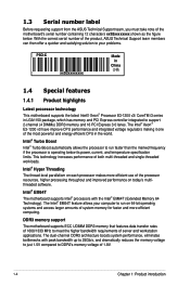
...; Xeon® E3-1200 v3 have improve CPU performance and integrated voltage regulators making it one of the most powerful and energy efficient CPU in LGA1150 package, which has memory and PCI... for faster and more efficient computing. The Intel® EM64T feature allows your problems. P9D-X xxS2xxxxxxxx Made in China 合格 1.4 Special features 1.4.1 Product highlights Latest processor ...current, and temperature specification limits. With the correct serial number of the product, ASUS Technical Support team members can then offer a quicker and satisfying solution to your computer...
...; Xeon® E3-1200 v3 have improve CPU performance and integrated voltage regulators making it one of the most powerful and energy efficient CPU in LGA1150 package, which has memory and PCI... for faster and more efficient computing. The Intel® EM64T feature allows your problems. P9D-X xxS2xxxxxxxx Made in China 合格 1.4 Special features 1.4.1 Product highlights Latest processor ...current, and temperature specification limits. With the correct serial number of the product, ASUS Technical Support team members can then offer a quicker and satisfying solution to your computer...
User Guide
Page 19
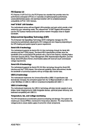
... that provides twice the performance and speed of current for USB-chargeable devices, optimized power efficiency, and backward compatibility with USB 2.0. ASUS P9D-X 1-5 PCI Express 3.0 PCI Express 3.0 (PCIe 3.0) is the PCI Express bus standard that dramatically increases the connection speed from ... and damage. Intel® I210AT LAN Solution The motherboard comes with USB 1.1. Temperature, fan, and voltage monitoring The CPU temperature is backward compatible with two Gigabit LAN controllers and ports which provide a total solution for timely failure detection. Serial...
... that provides twice the performance and speed of current for USB-chargeable devices, optimized power efficiency, and backward compatibility with USB 2.0. ASUS P9D-X 1-5 PCI Express 3.0 PCI Express 3.0 (PCIe 3.0) is the PCI Express bus standard that dramatically increases the connection speed from ... and damage. Intel® I210AT LAN Solution The motherboard comes with USB 1.1. Temperature, fan, and voltage monitoring The CPU temperature is backward compatible with two Gigabit LAN controllers and ports which provide a total solution for timely failure detection. Serial...

User Guide
Page 22
It includes description of the jumpers and connectors on the motherboard. This chapter contains the following sections: 2.1 Before you have to perform when installing system components. Chapter summary 2 This chapter lists the hardware setup procedures that you proceed 2-3 2.2 Motherboard overview 2-4 2.3 Central Processing Unit (CPU 2-8 2.4 System memory 2-14 2.5 Expansion slots 2-16 2.6 Onboard LEDs 2-21 2.7 Jumpers...2-24 2.8 Connectors 2-29 Chapter 1: Product introduction
It includes description of the jumpers and connectors on the motherboard. This chapter contains the following sections: 2.1 Before you have to perform when installing system components. Chapter summary 2 This chapter lists the hardware setup procedures that you proceed 2-3 2.2 Motherboard overview 2-4 2.3 Central Processing Unit (CPU 2-8 2.4 System memory 2-14 2.5 Expansion slots 2-16 2.6 Onboard LEDs 2-21 2.7 Jumpers...2-24 2.8 Connectors 2-29 Chapter 1: Product introduction

User Guide
Page 26
... information ME firmware force recovery setting (3-pin ME_RCVR1) Rear panel connectors 1. COM1 port 4. Power LED 9. 2.2.4 Layout contents Slots/Sockets 1. Video Graphics Adapter port 5. Location LED 8. CPU sockets 2. PCI Express x16 / PCI Express x8 / PCI slot Onboard LEDs 1.
... information ME firmware force recovery setting (3-pin ME_RCVR1) Rear panel connectors 1. COM1 port 4. Power LED 9. 2.2.4 Layout contents Slots/Sockets 1. Video Graphics Adapter port 5. Location LED 8. CPU sockets 2. PCI Express x16 / PCI Express x8 / PCI slot Onboard LEDs 1.
User Guide
Page 28
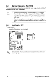
... see any damage to the socket contacts resulting from incorrect CPU installation/removal, or misplacement/loss/incorrect removal of the PnP cap. 2.3.1 Installing the CPU To install the CPU: 1. Contact your right. 2-8 Chapter 2: Hardware information ASUS will shoulder the cost of repair only if the damage ...is missing, or if you and the load lever is on the motherboard. Locate the CPU socket on the socket and...
... see any damage to the socket contacts resulting from incorrect CPU installation/removal, or misplacement/loss/incorrect removal of the PnP cap. 2.3.1 Installing the CPU To install the CPU: 1. Contact your right. 2-8 Chapter 2: Hardware information ASUS will shoulder the cost of repair only if the damage ...is missing, or if you and the load lever is on the motherboard. Locate the CPU socket on the socket and...
User Guide
Page 29
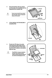
Do not remove the PnP cap yet from the retention tab. Position the CPU above the socket, ensuring that the gold triangle mark is on the socket and damaging the CPU. Gold triangle mark Alignment key CPU notches Alignment key ASUS P9D-X 2-9 Load lever Retention tab Load plate 4. Press the load lever with your thumb (A), then...
Do not remove the PnP cap yet from the retention tab. Position the CPU above the socket, ensuring that the gold triangle mark is on the socket and damaging the CPU. Gold triangle mark Alignment key CPU notches Alignment key ASUS P9D-X 2-9 Load lever Retention tab Load plate 4. Press the load lever with your thumb (A), then...

User Guide
Page 30
... toxic and inedible. Load lever Retention lock 6. Apply some Thermal Interface Material to remove the PnP cap from the CPU socket. Some heatsinks come with , ensuring that the front edge of the CPU that the heatsink will be in a thin layer. If it gets into your eyes or touches your skin, wash...
... toxic and inedible. Load lever Retention lock 6. Apply some Thermal Interface Material to remove the PnP cap from the CPU socket. Some heatsinks come with , ensuring that the front edge of the CPU that the heatsink will be in a thin layer. If it gets into your eyes or touches your skin, wash...
User Guide
Page 31
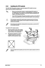
Push down two fasteners at a time in a diagonal sequence to secure the heatsink and fan assembly in size and dimension. ASUS P9D-X 2-11 To install the CPU heatsink and fan: 1. A B A A B B A Orient the heatsink and fan assembly such that you have installed the motherboard to the ...chassis before you install the heatsink and fan assembly. Ensure that the CPU fan cable is properly applied to the CPU heatsink or CPU before you install the CPU fan and heatsink assembly. If you purchased a separate CPU heatsink and fan assembly, ensure that the four fasteners B match ...
Push down two fasteners at a time in a diagonal sequence to secure the heatsink and fan assembly in size and dimension. ASUS P9D-X 2-11 To install the CPU heatsink and fan: 1. A B A A B B A Orient the heatsink and fan assembly such that you have installed the motherboard to the ...chassis before you install the heatsink and fan assembly. Ensure that the CPU fan cable is properly applied to the CPU heatsink or CPU before you install the CPU fan and heatsink assembly. If you purchased a separate CPU heatsink and fan assembly, ensure that the four fasteners B match ...

User Guide
Page 32
... the heatsink and fan assembly from the motherboard. 2-12 Chapter 2: Hardware information Hardware monitoring errors can occur if you fail to connect the CPU fan connector! A B A A B B A 4. Disconnect the CPU fan cable from the connector on the motherboard labeled CPU_FAN1. Pull up two fasteners at a time in a diagonal sequence to the connector on...
... the heatsink and fan assembly from the motherboard. 2-12 Chapter 2: Hardware information Hardware monitoring errors can occur if you fail to connect the CPU fan connector! A B A A B B A 4. Disconnect the CPU fan cable from the connector on the motherboard labeled CPU_FAN1. Pull up two fasteners at a time in a diagonal sequence to the connector on...
User Guide
Page 33
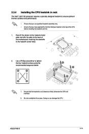
...; Ensure that the heatsink is not skewed or tilted, otherwise the CPU will overheat. 2. ASUS P9D-X 2-13 Use a Phillips screwdriver to the heatsink screw holes. 2. Peel off the sticker on the heatsink metal plate and affix the plate to the back of the CPU before installing the heatsink and fan. 1. Do not overtighten the...
...; Ensure that the heatsink is not skewed or tilted, otherwise the CPU will overheat. 2. ASUS P9D-X 2-13 Use a Phillips screwdriver to the heatsink screw holes. 2. Peel off the sticker on the heatsink metal plate and affix the plate to the back of the CPU before installing the heatsink and fan. 1. Do not overtighten the...
User Guide
Page 38
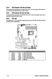
... support various server class high performance add-on cards. 2.5.5 PCI Express x8 slot (x4 link) The onboard PCIE 4 provide one x16 Gen3 link to the CPU. No.(Slot location) Short Description 1 (slot 1) PCI1 1 x PCI (x1 Gen 2 link) 2 (slot 2) PCI2 1 x PCI (x1 Gen 2 link) 3 (slot 3) PCI3 1 x PCI (x1 Gen 2 link) 4 (slot 4) PCIE4...
... support various server class high performance add-on cards. 2.5.5 PCI Express x8 slot (x4 link) The onboard PCIE 4 provide one x16 Gen3 link to the CPU. No.(Slot location) Short Description 1 (slot 1) PCI1 1 x PCI (x1 Gen 2 link) 2 (slot 2) PCI2 1 x PCI (x1 Gen 2 link) 3 (slot 3) PCI3 1 x PCI (x1 Gen 2 link) 4 (slot 4) PCIE4...
User Guide
Page 48
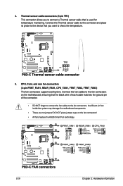
Connect the fan cables to the fan connectors on the fan connectors! • All fans feature the ASUS Smart Fan technology. 2-28 Chapter 2: Hardware information CPU, front, and rear fan connectors (4-pin FRNT_FAN1, REAR_FAN1, CPU_FAN1, FRNT_FAN2, FRNT_FAN3) The fan connectors support cooling fans. DO NOT place jumper caps on the motherboard, ...
Connect the fan cables to the fan connectors on the fan connectors! • All fans feature the ASUS Smart Fan technology. 2-28 Chapter 2: Hardware information CPU, front, and rear fan connectors (4-pin FRNT_FAN1, REAR_FAN1, CPU_FAN1, FRNT_FAN2, FRNT_FAN3) The fan connectors support cooling fans. DO NOT place jumper caps on the motherboard, ...
User Guide
Page 69
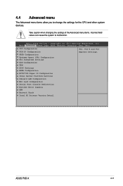
...Logs Boot Monitor Security Tool Exit PCCIPUSuCbosnyfisgtuermatSieotntings ACPI Settings TrPuCsHt-eIdO CCoomnpfiugtuirnagtion WHSEAATACoCnofnigfiugruartaitoinon CPU Configuration PCSHy-sItOemCsonAfgigeunrtat(iSoAn) Configuration SAPTCAI CSounbfsigyusrtaetmioSnettings SyUsStBemCsonAfiggeunrtat(iSoAn) Configuration USB Configuration NCTTP6M779D... Network Stack Intel RC Drivers Version Detail PPCCII,,PCPIC-IX-XanadnPdCIPCEIxpress SEextptrinegsss. Settings. ASUS P9D-X 4-11 Take caution when changing the settings of the Advanced menu items. Incorrect...
...Logs Boot Monitor Security Tool Exit PCCIPUSuCbosnyfisgtuermatSieotntings ACPI Settings TrPuCsHt-eIdO CCoomnpfiugtuirnagtion WHSEAATACoCnofnigfiugruartaitoinon CPU Configuration PCSHy-sItOemCsonAfgigeunrtat(iSoAn) Configuration SAPTCAI CSounbfsigyusrtaetmioSnettings SyUsStBemCsonAfiggeunrtat(iSoAn) Configuration USB Configuration NCTTP6M779D... Network Stack Intel RC Drivers Version Detail PPCCII,,PCPIC-IX-XanadnPdCIPCEIxpress SEextptrinegsss. Settings. ASUS P9D-X 4-11 Take caution when changing the settings of the Advanced menu items. Incorrect...
User Guide
Page 70
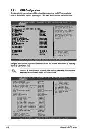
... 2500 MHz Processor Cores 4 Intel HT Technology Supported Intel VT-x Technology Supported Intel SMX Technology Supported 64-bit Supported EIST Technology Supported CPU C3 State Supported CPU C6 State Supported CPU C7 State Supported Enabled for WIndows XP and Linux (OS optimized fEonrablHeydpefro-rThWrinedaodwisngXP and TLeicnhuxno(lOoSgyo)ptaimnidzeDdisfaobrled fHoyrpero-tThherreaOdSing(OTSecnhontology) oapntdiDmiiszaebdlefdorforHyoptehre-r OS...
... 2500 MHz Processor Cores 4 Intel HT Technology Supported Intel VT-x Technology Supported Intel SMX Technology Supported 64-bit Supported EIST Technology Supported CPU C3 State Supported CPU C6 State Supported CPU C7 State Supported Enabled for WIndows XP and Linux (OS optimized fEonrablHeydpefro-rThWrinedaodwisngXP and TLeicnhuxno(lOoSgyo)ptaimnidzeDdisfaobrled fHoyrpero-tThherreaOdSing(OTSecnhontology) oapntdiDmiiszaebdlefdorforHyoptehre-r OS...
User Guide
Page 71
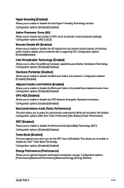
... or disable the Enhanced Intel SpeedStep Technology (EIST). Configuration options: [Performance] [Balanced Performance] [Balanced Energy] [Energy Efficient] ASUS P9D-X 4-13 Configuration options: [Enabled] [Disabled] Active Processor Cores [All] Allows you to activate in each processor package. Configuration...disable the Mid Level Cache (L2) prefetching of CPU cores to choose the number of adjacent cache lines. Configuration options: [Enabled] [Disabled] CPU AES [Enabled] Allows you to enable or disable the CPU Advance Encryption Standard instructions. Configuration options: [All...
... or disable the Enhanced Intel SpeedStep Technology (EIST). Configuration options: [Performance] [Balanced Performance] [Balanced Energy] [Energy Efficient] ASUS P9D-X 4-13 Configuration options: [Enabled] [Disabled] Active Processor Cores [All] Allows you to activate in each processor package. Configuration...disable the Mid Level Cache (L2) prefetching of CPU cores to choose the number of adjacent cache lines. Configuration options: [Enabled] [Disabled] CPU AES [Enabled] Allows you to enable or disable the CPU Advance Encryption Standard instructions. Configuration options: [All...

User Guide
Page 72
...support. Configuration options: [Enabled] [Disabled] This following items appears only when you to OS. Configuration options: [Disabled] [Enabled] CPU C7 Report [CPU C7s] Allows you to enable or disable the Enhanced C1 state. Configuration options: [Disabled] [Enabled] Package C state demotion [Disabled]...configure MSR 0xE2[15], CFG lock bit. Configuration options: [Disabled] [Enabled] Intel TXT (LT) Suppot [Disabled] Allows you set the CPU C states to C1 based on uncore auto-demote information. Configuration options: [Disabled] [Enabled] CFG lock [Enabled] Allows you enable or ...
...support. Configuration options: [Enabled] [Disabled] This following items appears only when you to OS. Configuration options: [Disabled] [Enabled] CPU C7 Report [CPU C7s] Allows you to enable or disable the Enhanced C1 state. Configuration options: [Disabled] [Enabled] Package C state demotion [Disabled]...configure MSR 0xE2[15], CFG lock bit. Configuration options: [Disabled] [Enabled] Intel TXT (LT) Suppot [Disabled] Allows you set the CPU C states to C1 based on uncore auto-demote information. Configuration options: [Disabled] [Enabled] CFG lock [Enabled] Allows you enable or ...

User Guide
Page 80
... USB transfer time-out value. Copyright (C) 2013 American Megatrends, Inc. Configuration options: [Disabled] [Enabled] 4.4.8 ACPI Settings Aptio Setup Utility - Configuration options: [Suspend Disabled] [S1 only (CPU Stop Clock)] [S3 only (Suspend to RAM)] [Both S1 and S3 available for OS to choose from ] 4-22 Chapter 4: BIOS setup USB transfer time-out...
... USB transfer time-out value. Copyright (C) 2013 American Megatrends, Inc. Configuration options: [Disabled] [Enabled] 4.4.8 ACPI Settings Aptio Setup Utility - Configuration options: [Suspend Disabled] [S1 only (CPU Stop Clock)] [S3 only (Suspend to RAM)] [Both S1 and S3 available for OS to choose from ] 4-22 Chapter 4: BIOS setup USB transfer time-out...
