User Manual
Page 4
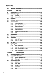
... Updating BIOS 3-30 3.10.1 ASUS Update utility 3-30 3.10.2 ASUS EZ Flash 2 utility 3-33 3.10.3 ASUS CrashFree BIOS 3 utility 3-34 3.10.4 ASUS BIOS Updater 3-35 Chapter 4: ...Software support 4.1 Installing an operating system 4-1 4.2 Support DVD information 4-1 4.2.1 Running the support DVD 4-1 4.2.2 Obtaining the software manuals 4-2 4.3 Software information 4-3 4.3.1 AI Suite II 4-3 4.3.2 DIGI+ VRM 4-4 4.3.3 BT GO 4-5 4.3.4 TurboV EVO 4-6 4.3.5 EPU 4-10 iv Contents 2.5 Turning...
... Updating BIOS 3-30 3.10.1 ASUS Update utility 3-30 3.10.2 ASUS EZ Flash 2 utility 3-33 3.10.3 ASUS CrashFree BIOS 3 utility 3-34 3.10.4 ASUS BIOS Updater 3-35 Chapter 4: ...Software support 4.1 Installing an operating system 4-1 4.2 Support DVD information 4-1 4.2.1 Running the support DVD 4-1 4.2.2 Obtaining the software manuals 4-2 4.3 Software information 4-3 4.3.1 AI Suite II 4-3 4.3.2 DIGI+ VRM 4-4 4.3.3 BT GO 4-5 4.3.4 TurboV EVO 4-6 4.3.5 EPU 4-10 iv Contents 2.5 Turning...

User Manual
Page 6
... regulations. DO NOT throw the mercury-containing button cell battery in municipal waste. This equipment generates, uses and can be determined by turning the equipment off and on a circuit different from digital apparatus set out in municipal waste. REACH Complying with manufacturer's instructions, may ...emissions from that to which can radiate radio frequency energy and, if not installed and used in our products at ASUS REACH website at http://csr.asus.com/english/REACH.htm. vi This product has been designed to Part 15 of Communications. Changes or modifications to...
... regulations. DO NOT throw the mercury-containing button cell battery in municipal waste. This equipment generates, uses and can be determined by turning the equipment off and on a circuit different from digital apparatus set out in municipal waste. REACH Complying with manufacturer's instructions, may ...emissions from that to which can radiate radio frequency energy and, if not installed and used in our products at ASUS REACH website at http://csr.asus.com/english/REACH.htm. vi This product has been designed to Part 15 of Communications. Changes or modifications to...
User Manual
Page 9
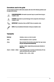
... perform certain tasks properly, take note of the following symbols used throughout this guide To ensure that you must press the Enter or Re� turn�k� ey. + + If you must press two or more keys simultaneously, the key names are linked with a plus sign (+). Typography Bold text Indicates a menu...
... perform certain tasks properly, take note of the following symbols used throughout this guide To ensure that you must press the Enter or Re� turn�k� ey. + + If you must press two or more keys simultaneously, the key names are linked with a plus sign (+). Typography Bold text Indicates a menu...
User Manual
Page 34
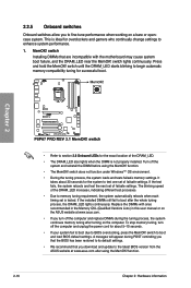
...to boot and load BIOS default settings. If the installed DIMMs still fail to the latest BIOS version from the ASUS website at www.asus.com. • If you turn off the system and reinstall the DIMM before using the MemOK! This is not properly installed. If the test ...DIMM is ideal for about 30 seconds for the system to test one set of failsafe settings. function. 2-16 Chapter 2: Hardware information Turn off the computer and unplug the power cord for overclockers and gamers who continually change settings to memory tuning requirement, the system automatically reboots...
...to boot and load BIOS default settings. If the installed DIMMs still fail to the latest BIOS version from the ASUS website at www.asus.com. • If you turn off the system and reinstall the DIMM before using the MemOK! This is not properly installed. If the test ...DIMM is ideal for about 30 seconds for the system to test one set of failsafe settings. function. 2-16 Chapter 2: Hardware information Turn off the computer and unplug the power cord for overclockers and gamers who continually change settings to memory tuning requirement, the system automatically reboots...
User Manual
Page 35
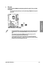
...application, adjust the BIOS setup program, or enable the TPU switch at the same time. Chapter 2 ASUS P8P67 PRO REV 3.1 2-17 Refer to section 2.2.6 Onboard LEDs for fast, yet stable clock speeds. 2. TPU switch Turning this switch to Enable will be activated after the next system bootup. • You may use ...the last setting you change the switch setting to Enable. For ensuring the system performance, turn the switch setting to Enable when the system is powered off. • The TPU LED (O2LED1) near the TPU switch lights when the ...
...application, adjust the BIOS setup program, or enable the TPU switch at the same time. Chapter 2 ASUS P8P67 PRO REV 3.1 2-17 Refer to section 2.2.6 Onboard LEDs for fast, yet stable clock speeds. 2. TPU switch Turning this switch to Enable will be activated after the next system bootup. • You may use ...the last setting you change the switch setting to Enable. For ensuring the system performance, turn the switch setting to Enable when the system is powered off. • The TPU LED (O2LED1) near the TPU switch lights when the ...
User Manual
Page 36
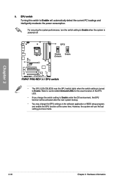
... when the system is powered off. • The EPU LED (O2LED2) near the EPU switch lights when the switch setting is turned to Enable under the OS environment, the EPU function will automatically detect the current PC loadings and intelligently moderate the power consumption. Chapter... 2 2-18 Chapter 2: Hardware information EPU switch Turning this switch to Enable will be activated after the next system bootup. • You may change the EPU settings in the software ...
... when the system is powered off. • The EPU LED (O2LED2) near the EPU switch lights when the switch setting is turned to Enable under the OS environment, the EPU function will automatically detect the current PC loadings and intelligently moderate the power consumption. Chapter... 2 2-18 Chapter 2: Hardware information EPU switch Turning this switch to Enable will be activated after the next system bootup. • You may change the EPU settings in the software ...

User Manual
Page 38
Chapter 2 2-20 Chapter 2: Hardware information TPU LED The TPU LED lights when the TPU switch is turned to Enable. 4. EPU LED The EPU LED lights when the EPU switch is turned to Enable. 3.
Chapter 2 2-20 Chapter 2: Hardware information TPU LED The TPU LED lights when the TPU switch is turned to Enable. 4. EPU LED The EPU LED lights when the EPU switch is turned to Enable. 3.

User Manual
Page 39
...before rebooting the system. Turn OFF the computer and unplug the power cord. 2. Removing the cap will cause system boot failure! • If the steps above do not need to clear the RTC when the system hangs due to clear the CMOS RTC RAM data. function. ASUS P8P67 PRO REV 3.1 2-21 Plug... the power cord and turn off is required to pins 1-2. 3. Keep the cap on CLRTC jumper default position. The onboard button cell battery powers the...
...before rebooting the system. Turn OFF the computer and unplug the power cord. 2. Removing the cap will cause system boot failure! • If the steps above do not need to clear the RTC when the system hangs due to clear the CMOS RTC RAM data. function. ASUS P8P67 PRO REV 3.1 2-21 Plug... the power cord and turn off is required to pins 1-2. 3. Keep the cap on CLRTC jumper default position. The onboard button cell battery powers the...
User Manual
Page 48
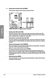
...power button/soft-off the system power. 2-30 Chapter 2: Hardware information Pressing the power switch for more than four seconds while the system is ON turns the system OFF. • Reset button (2-pin RESET) This 2-pin connector is for the chassis-mounted reset button for system reboot without... button (2-pin PWRSW) This connector is for the chassis-mounted system warning speaker. The speaker allows you turn on the BIOS settings. Pressing the power button turns the system on or puts the system in sleep or soft-off mode depending on the system power, and blinks when the system is...
...power button/soft-off the system power. 2-30 Chapter 2: Hardware information Pressing the power switch for more than four seconds while the system is ON turns the system OFF. • Reset button (2-pin RESET) This 2-pin connector is for the chassis-mounted reset button for system reboot without... button (2-pin PWRSW) This connector is for the chassis-mounted system warning speaker. The speaker allows you turn on the BIOS settings. Pressing the power button turns the system on or puts the system in sleep or soft-off mode depending on the system power, and blinks when the system is...
User Manual
Page 65
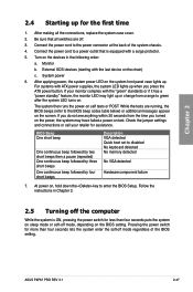
...followed by three short beeps One continuous beep followed by four short beeps Description VGA detected Quick boot set to green after the system LED turns on the screen. Follow the instructions in the following order: a. Chapter 2 2.4 Starting up for less than four seconds lets the ... protector. 5. While the tests are off mode, depending on self tests or POST. Turn on , hold down the key to the BIOS beep codes table below) or additional messages appear on . Monitor b. System power 6. ASUS P8P67 PRO REV 3.1 2-47 After making all switches are running, the BIOS beeps (refer to ...
...followed by three short beeps One continuous beep followed by four short beeps Description VGA detected Quick boot set to green after the system LED turns on the screen. Follow the instructions in the following order: a. Chapter 2 2.4 Starting up for less than four seconds lets the ... protector. 5. While the tests are off mode, depending on self tests or POST. Turn on , hold down the key to the BIOS beep codes table below) or additional messages appear on . Monitor b. System power 6. ASUS P8P67 PRO REV 3.1 2-47 After making all switches are running, the BIOS beeps (refer to ...

User Manual
Page 67
... you not change the default BIOS settings except in the EZ Mode/Advanced Mode screen. You can also turn the system off and then turn it lets you scroll through the various submenus and select from the Exit/Advanced Mode button in the following...overclocking settings, advanced power management, and boot device configuration that you want to use as easy to ensure system compatibility and stability. Chapter 3 ASUS P8P67 PRO REV 3.1 3-1 We strongly recommend that are for reference purposes only, and may result to instability or failure to enter the Setup utility....
... you not change the default BIOS settings except in the EZ Mode/Advanced Mode screen. You can also turn the system off and then turn it lets you scroll through the various submenus and select from the Exit/Advanced Mode button in the following...overclocking settings, advanced power management, and boot device configuration that you want to use as easy to ensure system compatibility and stability. Chapter 3 ASUS P8P67 PRO REV 3.1 3-1 We strongly recommend that are for reference purposes only, and may result to instability or failure to enter the Setup utility....

User Manual
Page 88
... the system. [Ctrl-Esc] Sets the Ctrl+Esc key on the PS/2 keyboard to turn on the system. [Power Key] Sets Power key on the PS/2 keyboard to turn on state, whatever the system state was before the AC power loss. Power On By PCIE [Disabled] [Disabled] Disables the PCIE devices ...] The system goes into off or on the system through a PCI LAN or modem card. Power On By PCI [Disabled] [Disabled] Disables the PME to turn on the +5VSB lead. 3.5.7 APM EFI BIOS Utility - Power On By PS/2 Mouse [Disabled] [Disabled] Disables the Power On by a PS/2 mouse. [Enabled] Enables ...
... the system. [Ctrl-Esc] Sets the Ctrl+Esc key on the PS/2 keyboard to turn on the system. [Power Key] Sets Power key on the PS/2 keyboard to turn on state, whatever the system state was before the AC power loss. Power On By PCIE [Disabled] [Disabled] Disables the PCIE devices ...] The system goes into off or on the system through a PCI LAN or modem card. Power On By PCI [Disabled] [Disabled] Disables the PME to turn on the +5VSB lead. 3.5.7 APM EFI BIOS Utility - Power On By PS/2 Mouse [Disabled] [Disabled] Disables the Power On by a PS/2 mouse. [Enabled] Enables ...
User Manual
Page 100
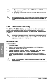
... the USB flash drive containing the BIOS file to ensure system compatibility and stability. When found, the utility reads the BIOS file and enters ASUS EZ Flash 2 utility automatically. 4. Recovering the BIOS To recover the BIOS: 1. Doing so can cause system boot failure! See section ...stability, we recommend that you to enter BIOS Setup to load default BIOS values. Turn on the ASUS official website. The utility automatically checks the devices for details. 3.10.3 ASUS CrashFree BIOS 3 utility The ASUS CrashFree BIOS 3 utility is an auto recovery tool that contains the BIOS file....
... the USB flash drive containing the BIOS file to ensure system compatibility and stability. When found, the utility reads the BIOS file and enters ASUS EZ Flash 2 utility automatically. 4. Recovering the BIOS To recover the BIOS: 1. Doing so can cause system boot failure! See section ...stability, we recommend that you to enter BIOS Setup to load default BIOS values. Turn on the ASUS official website. The utility automatically checks the devices for details. 3.10.3 ASUS CrashFree BIOS 3 utility The ASUS CrashFree BIOS 3 utility is an auto recovery tool that contains the BIOS file....
User Manual
Page 101
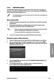
... or USB flash drive in FAT32/16 format and single partition. 2. Before updating BIOS 1. Turn off the computer and disconnect all SATA hard disk drives (optional). Boot your computer. C:\>d: D:\> Chapter 3 ASUS P8P67 PRO REV 3.1 3-35 3.10.4 ASUS BIOS Updater The ASUS BIOS Updater allows you can use as a backup when the BIOS fails or gets corrupted...
... or USB flash drive in FAT32/16 format and single partition. 2. Before updating BIOS 1. Turn off the computer and disconnect all SATA hard disk drives (optional). Boot your computer. C:\>d: D:\> Chapter 3 ASUS P8P67 PRO REV 3.1 3-35 3.10.4 ASUS BIOS Updater The ASUS BIOS Updater allows you can use as a backup when the BIOS fails or gets corrupted...

User Manual
Page 119
...-RAID Disk Non-RAID Disk Non-RAID Disk Chapter 4 [↑↓]-Select ASUS P8P67 PRO REV 3.1 [ESC]-Exit [ENTER]-Select Menu 4-15 To install the SATA hard disks for details on the system. 2. Connect a SATA power cable to [RAID Mode]. 4. Turn on entering and navigating through the BIOS Setup. v10.0.0.1032 Copyright(C) 2003-10...
...-RAID Disk Non-RAID Disk Non-RAID Disk Chapter 4 [↑↓]-Select ASUS P8P67 PRO REV 3.1 [ESC]-Exit [ENTER]-Select Menu 4-15 To install the SATA hard disks for details on the system. 2. Connect a SATA power cable to [RAID Mode]. 4. Turn on entering and navigating through the BIOS Setup. v10.0.0.1032 Copyright(C) 2003-10...
User Manual
Page 127
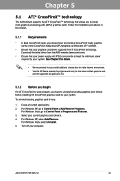
... CrossFireX mode, you should have to uninstall all current applications. 2. To uninstall existing graphics card drivers: 1. For Windows XP, select Add/Remove. Turn off your current graphics card driver/s. 4. ASUS P8P67 PRO REV 3.1 5-1 Select your computer. Download the latest driver from the AMD website (www.amd.com). • Ensure that your power supply unit...
... CrossFireX mode, you should have to uninstall all current applications. 2. To uninstall existing graphics card drivers: 1. For Windows XP, select Add/Remove. Turn off your current graphics card driver/s. 4. ASUS P8P67 PRO REV 3.1 5-1 Select your computer. Download the latest driver from the AMD website (www.amd.com). • Ensure that your power supply unit...


