User Guide
Page 9
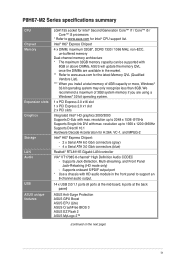
P8H67-M2 Series specifications summary CPU Chipset Memory Expansion slots Graphics Storage LAN Audio USB ASUS unique features LGA1155 socket for Intel® Second Generation Core™ i7 / Core™ i5 / Core™ i3 processors * Refer to 2048 x 1536 @75Hz Supports Single-link DVI with max. Intel® H67... ports at the back panel) ASUS Anti-Surge Protection ASUS GPU Boost ASUS EPU (Lite) ASUS CrashFree BIOS 3 ASUS EZ Flash 2 ASUS MyLogo 2™ (continued on the next page) ix resolution up to www.asus.com for H.264, VC-1, and MPEG-2 Intel® H67 Express Chipset: - 2 x Serial...
P8H67-M2 Series specifications summary CPU Chipset Memory Expansion slots Graphics Storage LAN Audio USB ASUS unique features LGA1155 socket for Intel® Second Generation Core™ i7 / Core™ i5 / Core™ i3 processors * Refer to 2048 x 1536 @75Hz Supports Single-link DVI with max. Intel® H67... ports at the back panel) ASUS Anti-Surge Protection ASUS GPU Boost ASUS EPU (Lite) ASUS CrashFree BIOS 3 ASUS EZ Flash 2 ASUS MyLogo 2™ (continued on the next page) ix resolution up to www.asus.com for H.264, VC-1, and MPEG-2 Intel® H67 Express Chipset: - 2 x Serial...
User Guide
Page 12
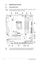
DO NOT overtighten the screws! Doing so can damage the motherboard. 1-2 ASUS P8H67-M2 Series The edge with external ports goes to the rear part of the chassis. 1 23 1 4 5 22.4cm(8.8in) DVI KB_USB56 EPU ATX12V CPU_FAN ....4cm(9.6in) USB34 EATXPWR LAN1_USB12 Lithium Cell CHA_FAN CMOS Power 2 AUDIO PCIEX16 RTL 8111E P8H67-M2/TPM/SI PCI1 7 SB_PWR 8 TPM IC asmedia ASM1083 PCI2 VIA VT1708S SPDIF_OUT PCIEX1_1 AAFP USB1314 USB1112 USB910 Intel® H67 CHASSIS CLRTC 32Mb BIOS SATA3G_3 SATA3G_1 SATA6G_1 USB78 F_PANEL SATA3G_4 SATA3G_2 SATA6G_2 SPEAKER 9 10 16...
DO NOT overtighten the screws! Doing so can damage the motherboard. 1-2 ASUS P8H67-M2 Series The edge with external ports goes to the rear part of the chassis. 1 23 1 4 5 22.4cm(8.8in) DVI KB_USB56 EPU ATX12V CPU_FAN ....4cm(9.6in) USB34 EATXPWR LAN1_USB12 Lithium Cell CHA_FAN CMOS Power 2 AUDIO PCIEX16 RTL 8111E P8H67-M2/TPM/SI PCI1 7 SB_PWR 8 TPM IC asmedia ASM1083 PCI2 VIA VT1708S SPDIF_OUT PCIEX1_1 AAFP USB1314 USB1112 USB910 Intel® H67 CHASSIS CLRTC 32Mb BIOS SATA3G_3 SATA3G_1 SATA6G_1 USB78 F_PANEL SATA3G_4 SATA3G_2 SATA6G_2 SPEAKER 9 10 16...
User Guide
Page 13
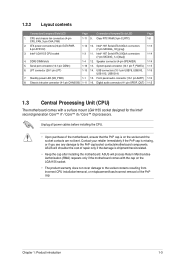
...contacts are not bent. Chapter 1: Product introduction 1-3 1.2.2 Layout contents Connectors/Jumpers/Slots/LED Page Connectors/Jumpers/Slots/LED Page 1. Intel® H67 Serial ATA 6.0Gb/s connectors 1-13 4-pin ATX12V) (7-pin SATA6G_1/2 [gray]) 3. Speaker connector (4-pin SPEAKER) 1-14 5. System panel connector... cover damage to the PnP cap/socket contacts/motherboard components. Serial port connector (10-1 pin COM1) 1-16 13. ASUS will process Return Merchandise Authorization (RMA) requests only if the motherboard comes with a surface mount LGA1155 socket designed for ...
...contacts are not bent. Chapter 1: Product introduction 1-3 1.2.2 Layout contents Connectors/Jumpers/Slots/LED Page Connectors/Jumpers/Slots/LED Page 1. Intel® H67 Serial ATA 6.0Gb/s connectors 1-13 4-pin ATX12V) (7-pin SATA6G_1/2 [gray]) 3. Speaker connector (4-pin SPEAKER) 1-14 5. System panel connector... cover damage to the PnP cap/socket contacts/motherboard components. Serial port connector (10-1 pin COM1) 1-16 13. ASUS will process Return Merchandise Authorization (RMA) requests only if the motherboard comes with a surface mount LGA1155 socket designed for ...
User Guide
Page 23
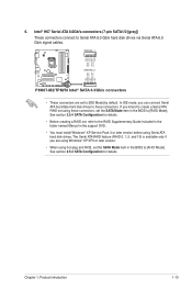
...to create a Serial ATA RAID set using these connectors, set the SATA Mode item in the BIOS to these connectors. Intel® H67 Serial ATA 6.0Gb/s connectors (7-pin SATA1/2 [gray]) These connectors connect to [RAID Mode]. If you are set to the RAID ...6. See section 2.5.4 SATA Configuration for details. SATA6G_1 GND RSATA_TXP1 RSATA_TXN1 GND RSATA_RXP1 RSATA_RXN1 GND GND RSATA_RXN2 RSATA_RXP2 GND RSATA_TXN2 RSATA_TXP2 GND P8H67-M2/TPM/SI SATA6G_2 P8H67-M2/TPM/SI Intel® SATA 6.0Gb/s connectors • These connectors are using Windows® XP SP3 or later version....
...to create a Serial ATA RAID set using these connectors, set the SATA Mode item in the BIOS to these connectors. Intel® H67 Serial ATA 6.0Gb/s connectors (7-pin SATA1/2 [gray]) These connectors connect to [RAID Mode]. If you are set to the RAID ...6. See section 2.5.4 SATA Configuration for details. SATA6G_1 GND RSATA_TXP1 RSATA_TXN1 GND RSATA_RXP1 RSATA_RXN1 GND GND RSATA_RXN2 RSATA_RXP2 GND RSATA_TXN2 RSATA_TXP2 GND P8H67-M2/TPM/SI SATA6G_2 P8H67-M2/TPM/SI Intel® SATA 6.0Gb/s connectors • These connectors are using Windows® XP SP3 or later version....
User Guide
Page 24
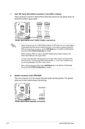
... Serial ATA boot/data hard disk drives to [RAID Mode]. SPEAKER +5V GND GND Speaker Out P8H67-M2/TPM/SI PIN 1 P8H67-M2/TPM/SI Speaker connector 1-14 ASUS P8H67-M2 Series If you to the RAID Supplementary Guide included in the folder named Manual in the BIOS...a Serial ATA RAID set using these connectors. 7. The Serial ATA RAID feature (RAID 0, 1, 5, and 10) is for details. 8. Intel® H67 Serial ATA 3.0Gb/s connectors (7-pin SATA1~4 [blue]) These connectors connect to [AHCI Mode]. SATA3G_3 SATA3G_1 GND RSATA_TXP1 RSATA_TXN1 GND RSATA_RXP1 RSATA_RXN1 GND GND RSATA_TXP3 ...
... Serial ATA boot/data hard disk drives to [RAID Mode]. SPEAKER +5V GND GND Speaker Out P8H67-M2/TPM/SI PIN 1 P8H67-M2/TPM/SI Speaker connector 1-14 ASUS P8H67-M2 Series If you to the RAID Supplementary Guide included in the folder named Manual in the BIOS...a Serial ATA RAID set using these connectors. 7. The Serial ATA RAID feature (RAID 0, 1, 5, and 10) is for details. 8. Intel® H67 Serial ATA 3.0Gb/s connectors (7-pin SATA1~4 [blue]) These connectors connect to [AHCI Mode]. SATA3G_3 SATA3G_1 GND RSATA_TXP1 RSATA_TXN1 GND RSATA_RXP1 RSATA_RXN1 GND GND RSATA_TXP3 ...