P8H61-MX R2.0 User's Manual
Page 3
Contents Safety information vi About this guide vii P8H61-MX Series specifications summary ix Chapter 1 Product introduction 1.1 Before you proceed 1-1 1.2 Motherboard overview 1-2 1.2.1 Placement direction 1-2 1.2.2 Screw holes 1-2 1.2.3 Motherboard layout 1-3 1.2.4 ...1.5.2 Configuring an expansion card 1-18 1.5.3 PCI Express x1 slot 1-18 1.5.4 PCI Express x16 slot 1-18 1.6 Jumpers 1-19 1.7 Connectors 1-20 1.7.1 Rear panel connectors 1-20 1.7.2 Internal connectors 1-21 1.8 Software support 1-26 1.8.1 Installing an operating system 1-26 1.8.2 Support DVD information 1-26 iii
Contents Safety information vi About this guide vii P8H61-MX Series specifications summary ix Chapter 1 Product introduction 1.1 Before you proceed 1-1 1.2 Motherboard overview 1-2 1.2.1 Placement direction 1-2 1.2.2 Screw holes 1-2 1.2.3 Motherboard layout 1-3 1.2.4 ...1.5.2 Configuring an expansion card 1-18 1.5.3 PCI Express x1 slot 1-18 1.5.4 PCI Express x16 slot 1-18 1.6 Jumpers 1-19 1.7 Connectors 1-20 1.7.1 Rear panel connectors 1-20 1.7.2 Internal connectors 1-21 1.8 Software support 1-26 1.8.1 Installing an operating system 1-26 1.8.2 Support DVD information 1-26 iii
P8H61-MX R2.0 User's Manual
Page 6
... safety • Before installing the motherboard and adding devices on a stable surface. • If you add a device. • Before connecting or removing signal cables from connectors, slots, sockets and circuitry. • Avoid dust, humidity, and temperature extremes. vi If you are not sure about the voltage of the electrical outlet you...
... safety • Before installing the motherboard and adding devices on a stable surface. • If you add a device. • Before connecting or removing signal cables from connectors, slots, sockets and circuitry. • Avoid dust, humidity, and temperature extremes. vi If you are not sure about the voltage of the electrical outlet you...
P8H61-MX R2.0 User's Manual
Page 9
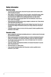
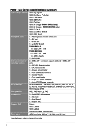
...P8H61-MX USB3 Intel® H61 Express Chipset - 8 x USB 2.0/1.1 ports (4 ports at mid-board, 4 ports at rear) ASMedia® ASM1042 controller - 2 x USB 3.0 ports (2 ports at rear) (continued on the next page) ix Resolution: 1920 x 1200 @60Hz D-SUB with Max. Storage Intel® H61 Express Chipset: - 4 x Serial ATA 3.0 Gb/s connectors... recognize less than 3GB. P8H61-MX Series specifications summary CPU LGA1155 socket for Intel® 3rd/2nd Generation Core™ i7 / i5 / i3 / Pentium® / Celeron® processors Supports 22/32nm CPU *Refer to www.asus.com for Intel® ...
...P8H61-MX USB3 Intel® H61 Express Chipset - 8 x USB 2.0/1.1 ports (4 ports at mid-board, 4 ports at rear) ASMedia® ASM1042 controller - 2 x USB 3.0 ports (2 ports at rear) (continued on the next page) ix Resolution: 1920 x 1200 @60Hz D-SUB with Max. Storage Intel® H61 Express Chipset: - 4 x Serial ATA 3.0 Gb/s connectors... recognize less than 3GB. P8H61-MX Series specifications summary CPU LGA1155 socket for Intel® 3rd/2nd Generation Core™ i7 / i5 / i3 / Pentium® / Celeron® processors Supports 22/32nm CPU *Refer to www.asus.com for Intel® ...
P8H61-MX R2.0 User's Manual
Page 10
... ASUS unique features ASUS MyLogo 2™ ASUS Anti-Surge Protection ASUS UEFI BIOS ASUS EZ Flash 2 ASUS FanXpert ASUS AI Charger (P8H61-MX R2.0 only) ASUS AI Charger+ (P8H61-MX USB3 only) ASUS Q-Fan 2 ASUS CrashFree BIOS 3 ASUS GPU Boost Rear panel ports 1 x PS/2 keyboard / mouse combo port 1 x DVI port 1 x D-Sub port 1 x LAN (RJ-45) port P8H61-MX R2.0: - 6 x USB 2.0/1.1 ports P8H61-MX USB3: - 4 x USB 2.0/1.1 ports - 2 x USB 3.0 ports 3 x Audio jacks Internal connectors...
... ASUS unique features ASUS MyLogo 2™ ASUS Anti-Surge Protection ASUS UEFI BIOS ASUS EZ Flash 2 ASUS FanXpert ASUS AI Charger (P8H61-MX R2.0 only) ASUS AI Charger+ (P8H61-MX USB3 only) ASUS Q-Fan 2 ASUS CrashFree BIOS 3 ASUS GPU Boost Rear panel ports 1 x PS/2 keyboard / mouse combo port 1 x DVI port 1 x D-Sub port 1 x LAN (RJ-45) port P8H61-MX R2.0: - 6 x USB 2.0/1.1 ports P8H61-MX USB3: - 4 x USB 2.0/1.1 ports - 2 x USB 3.0 ports 3 x Audio jacks Internal connectors...
P8H61-MX R2.0 User's Manual
Page 14
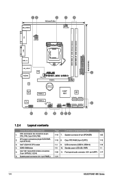
... P8H61-MX USB3 CHA_FAN PCIEX16 RTL 8111F Lithium Cell CMOS Power Super I/O PCIEX1_1 Intel® 64Mb H61 BIOS VIA VT1708S AAFP SATA3G_3 SATA3G_1 PCIEX1_2 SB_PWR USB910 USB78 SPEAKER CLRTC SATA3G_4 SATA3G_2 5 F_PANEL 11 10 9 8 76 1.2.4 Layout contents Connectors/Jumpers/Slots/LED 1. USB connectors (USB78, USB910) 1-19 1-9 10. Front panel audio connector (10-1 pin AAFP) 1-17 1-21 1-4 ASUS P8H61-MX...
... P8H61-MX USB3 CHA_FAN PCIEX16 RTL 8111F Lithium Cell CMOS Power Super I/O PCIEX1_1 Intel® 64Mb H61 BIOS VIA VT1708S AAFP SATA3G_3 SATA3G_1 PCIEX1_2 SB_PWR USB910 USB78 SPEAKER CLRTC SATA3G_4 SATA3G_2 5 F_PANEL 11 10 9 8 76 1.2.4 Layout contents Connectors/Jumpers/Slots/LED 1. USB connectors (USB78, USB910) 1-19 1-9 10. Front panel audio connector (10-1 pin AAFP) 1-17 1-21 1-4 ASUS P8H61-MX...
P8H61-MX R2.0 User's Manual
Page 16
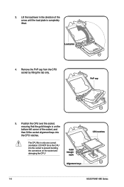
Position the CPU over the socket, ensuring that the gold triangle is completely lifted. 3. PnP cap 5. Gold triangle mark Alignment keys CPU notches 1-6 ASUS P8H61-MX Series Load plate 4. Lift the load lever in only one correct orientation. Remove the PnP cap from the CPU socket by lifting the tab only. ... plate is on the bottom‑left corner of the socket, and then fit the socket alignment keys into the socket to prevent bending the connectors on the socket and damaging the CPU!
Position the CPU over the socket, ensuring that the gold triangle is completely lifted. 3. PnP cap 5. Gold triangle mark Alignment keys CPU notches 1-6 ASUS P8H61-MX Series Load plate 4. Lift the load lever in only one correct orientation. Remove the PnP cap from the CPU socket by lifting the tab only. ... plate is on the bottom‑left corner of the socket, and then fit the socket alignment keys into the socket to prevent bending the connectors on the socket and damaging the CPU!
P8H61-MX R2.0 User's Manual
Page 18
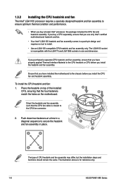
B Orient the heatsink and fan assembly A such that the CPU fan cable is for reference only. 1-8 ASUS P8H61-MX Series The illustration above is closest to the CPU fan connector. 2. If you buy a boxed Intel® processor, the package includes the CPU fan and heatsink assembly. To install the CPU heatsink and fan: 1. If you...
B Orient the heatsink and fan assembly A such that the CPU fan cable is for reference only. 1-8 ASUS P8H61-MX Series The illustration above is closest to the CPU fan connector. 2. If you buy a boxed Intel® processor, the package includes the CPU fan and heatsink assembly. To install the CPU heatsink and fan: 1. If you...
P8H61-MX R2.0 User's Manual
Page 19
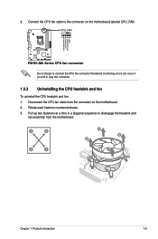
... two fasteners at a time in a diagonal sequence to connect the CPU fan connector! CPU_FAN CPU FAN PWM CPU FAN IN CPU FAN PWR GND P8H61-MX R2.0 P8H61-MX Series CPU fan connector Do not forget to disengage the heatsink and fan assembly from the connector on the motherboard labeled CPU_FAN. Rotate each fastener counterclockwise. 3. 3. A B B A A B B A Chapter 1: Product...
... two fasteners at a time in a diagonal sequence to connect the CPU fan connector! CPU_FAN CPU FAN PWM CPU FAN IN CPU FAN PWR GND P8H61-MX R2.0 P8H61-MX Series CPU fan connector Do not forget to disengage the heatsink and fan assembly from the connector on the motherboard labeled CPU_FAN. Rotate each fastener counterclockwise. 3. 3. A B B A A B B A Chapter 1: Product...
P8H61-MX R2.0 User's Manual
Page 28
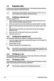
... expansion card. Assign an IRQ to the card. 3. 1.5 Expansion slots In the future, you intend to use . 4. Align the card connector with it by Intel® 3rd generation processors. 1-18 ASUS P8H61-MX Series Otherwise, conflicts will arise between the two PCI groups, making the system unstable and the card inoperable. 1.5.3 PCI Express x1...
... expansion card. Assign an IRQ to the card. 3. 1.5 Expansion slots In the future, you intend to use . 4. Align the card connector with it by Intel® 3rd generation processors. 1-18 ASUS P8H61-MX Series Otherwise, conflicts will arise between the two PCI groups, making the system unstable and the card inoperable. 1.5.3 PCI Express x1...
P8H61-MX R2.0 User's Manual
Page 30
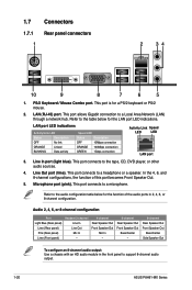
... To configure an 8-channel audio output: Use a chassis with an HD audio module in 2, 4, 6, or 8-channel configuration. 1.7 1.7.1 1 Connectors Rear panel connectors 2 34 10 9 8 7 6 5 1. This port allows Gigabit connection to support 8-channel audio output. 1-20 ASUS P8H61-MX Series Line In port (light blue). Refer to a headphone or a speaker. This port connects to the audio configuration...
... To configure an 8-channel audio output: Use a chassis with an HD audio module in 2, 4, 6, or 8-channel configuration. 1.7 1.7.1 1 Connectors Rear panel connectors 2 34 10 9 8 7 6 5 1. This port allows Gigabit connection to support 8-channel audio output. 1-20 ASUS P8H61-MX Series Line In port (light blue). Refer to a headphone or a speaker. This port connects to the audio configuration...
P8H61-MX R2.0 User's Manual
Page 31
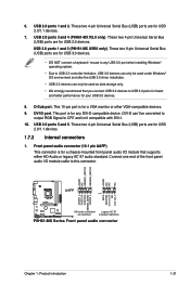
...RGB Signal to CRT and isn't compatible with DVI-I /O module that you connect USB 3.0 devices to this connector. D-Sub port. USB 3.0 ports 1 and 2 (P8H61-MX USB3 only). This 15-pin port is for USB 2.0 devices. Connect one end of the front panel audio ... out_L PORT1 L PORT1 R PORT2 R SENSE_SEND PORT2 L P8H61-MX R2.0 HD-audio-compliant Legacy AC'97 pin definition compliant definition P8H61-MX Series Front panel audio connector Chapter 1: Product introduction 1-21 Front panel audio connector (10-1 pin AAFP) This connector is for a VGA monitor or other VGA-compatible devices...
...RGB Signal to CRT and isn't compatible with DVI-I /O module that you connect USB 3.0 devices to this connector. D-Sub port. USB 3.0 ports 1 and 2 (P8H61-MX USB3 only). This 15-pin port is for USB 2.0 devices. Connect one end of the front panel audio ... out_L PORT1 L PORT1 R PORT2 R SENSE_SEND PORT2 L P8H61-MX R2.0 HD-audio-compliant Legacy AC'97 pin definition compliant definition P8H61-MX Series Front panel audio connector Chapter 1: Product introduction 1-21 Front panel audio connector (10-1 pin AAFP) This connector is for a VGA monitor or other VGA-compatible devices...

P8H61-MX R2.0 User's Manual
Page 32
...GND GND +3 Volts +12 Volts +12 Volts +5V Standby Power OK PIN 1 GND +5 Volts GND +5 Volts GND +3 Volts +3 Volts PIN 1 P8H61-MX Series ATX power connectors GND +5 Volts +5 Volts +5 Volts -5 Volts GND GND GND PSON# GND -12 Volts +3 Volts • For a fully configured system, we ...AC'97 front panel audio module to this connector, set the item to the Recommended Power Supply Wattage Calculator at http://support.asus. ATX power connectors (24-pin EATXPWR, 4-pin ATX12V) These connectors are designed to [HD]. By default, this connector is inadequate. • If you are ...
...GND GND +3 Volts +12 Volts +12 Volts +5V Standby Power OK PIN 1 GND +5 Volts GND +5 Volts GND +3 Volts +3 Volts PIN 1 P8H61-MX Series ATX power connectors GND +5 Volts +5 Volts +5 Volts -5 Volts GND GND GND PSON# GND -12 Volts +3 Volts • For a fully configured system, we ...AC'97 front panel audio module to this connector, set the item to the Recommended Power Supply Wattage Calculator at http://support.asus. ATX power connectors (24-pin EATXPWR, 4-pin ATX12V) These connectors are designed to [HD]. By default, this connector is inadequate. • If you are ...
P8H61-MX R2.0 User's Manual
Page 33
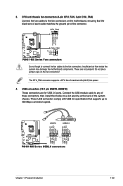
... CPU FAN PWM CPU FAN IN CPU FAN PWR GND P8H61-MX R2.0 CHA_FAN Rotation +12V GND P8H61-MX Series Fan connectors Do not forget to connect the fan cables to a slot opening at the back of the connector. Do not place jumper caps on the motherboard, ensuring that... supports up to the fan connectors on the fan connectors! USB+5V USB_P6USB_P6+ GND NC USB+5V USB_P8USB_P8+ GND NC USB78 USB910 USB+5V USB_P5USB_P5+ GND USB+5V USB_P7USB_P7+ GND P8H61-MX R2.0 PIN 1 PIN 1 P8H61-MX Series USB2.0 connectors Chapter 1: Product introduction 1-23 Connect the USB...
... CPU FAN PWM CPU FAN IN CPU FAN PWR GND P8H61-MX R2.0 CHA_FAN Rotation +12V GND P8H61-MX Series Fan connectors Do not forget to connect the fan cables to a slot opening at the back of the connector. Do not place jumper caps on the motherboard, ensuring that... supports up to the fan connectors on the fan connectors! USB+5V USB_P6USB_P6+ GND NC USB+5V USB_P8USB_P8+ GND NC USB78 USB910 USB+5V USB_P5USB_P5+ GND USB+5V USB_P7USB_P7+ GND P8H61-MX R2.0 PIN 1 PIN 1 P8H61-MX Series USB2.0 connectors Chapter 1: Product introduction 1-23 Connect the USB...
P8H61-MX R2.0 User's Manual
Page 34
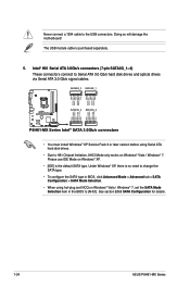
Intel® H61 Serial ATA 3.0Gb/s connectors (7-pin SATA3G_1~4) These connectors connect to [AHCI]. See section 2.5.3 SATA Configuration for details. 1-24 ASUS P8H61-MX Series Doing so will damage the motherboard! Please use IDE Mode on Windows® XP. • [IDE... RSATA_RXP3 GND GND RSATA_TXP1 RSATA_TXN1 GND RSATA_RXN1 RSATA_RXP1 GND P8H61-MX R2.0 SATA3G_4 SATA3G_2 GND RSATA_RXP4 RSATA_RXN4 GND RSATA_TXN4 RSATA_TXP4 GND GND RSATA_RXP2 RSATA_RXN2 GND RSATA_TXN2 RSATA_TXP2 GND P8H61-MX Series Intel® SATA 3.0Gb/s connectors • You must install Windows® XP Service...
Intel® H61 Serial ATA 3.0Gb/s connectors (7-pin SATA3G_1~4) These connectors connect to [AHCI]. See section 2.5.3 SATA Configuration for details. 1-24 ASUS P8H61-MX Series Doing so will damage the motherboard! Please use IDE Mode on Windows® XP. • [IDE... RSATA_RXP3 GND GND RSATA_TXP1 RSATA_TXN1 GND RSATA_RXN1 RSATA_RXP1 GND P8H61-MX R2.0 SATA3G_4 SATA3G_2 GND RSATA_RXP4 RSATA_RXN4 GND RSATA_TXN4 RSATA_TXP4 GND GND RSATA_RXP2 RSATA_RXN2 GND RSATA_TXN2 RSATA_TXP2 GND P8H61-MX Series Intel® SATA 3.0Gb/s connectors • You must install Windows® XP Service...
P8H61-MX R2.0 User's Manual
Page 35
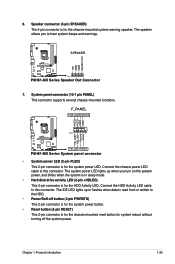
... system beeps and warnings. +5V GND GND Speaker Out P8H61-MX R2.0 SPEAKER PIN 1 P8H61-MX Series Speaker Out Connector 7. Connect the HDD Activity LED cable to this connector. Speaker connector (4-pin SPEAKER) The 4-pin connector is for the chassis-mounted reset button for the HDD ...drive activity LED (2-pin +HDLED) This 2-pin connector is for the chassis-mounted system warning speaker. 6. Ground Reset P8H61-MX R2.0 PIN 1 +HD_LED RESET P8H61-MX Series System panel connector • System power LED (2-pin PLED) This 2-pin connector is for system reboot without turning off the ...
... system beeps and warnings. +5V GND GND Speaker Out P8H61-MX R2.0 SPEAKER PIN 1 P8H61-MX Series Speaker Out Connector 7. Connect the HDD Activity LED cable to this connector. Speaker connector (4-pin SPEAKER) The 4-pin connector is for the chassis-mounted reset button for the HDD ...drive activity LED (2-pin +HDLED) This 2-pin connector is for the chassis-mounted system warning speaker. 6. Ground Reset P8H61-MX R2.0 PIN 1 +HD_LED RESET P8H61-MX Series System panel connector • System power LED (2-pin PLED) This 2-pin connector is for system reboot without turning off the ...

P8H61-MX R2.0 User's Manual
Page 56
...panel audio module supports. [HD] Sets the front panel audio connector (AAFP) mode to high definition audio. [AC97] Sets the front panel audio connector (AAFP) mode to [Enabled]. Asmedia USB 3.0 Battery Charging Support [Disabled] (P8H61-MX USB3 only) This item appears only when the Asmedia USB 3.0 Controller...audio connector (AAFP) mode to enable or disable the PXE OptionRom of the Realtek LAN controller. Front Panel Type [HD] Allows you to legacy AC'97 or highdefinition audio depending on state, whatever the system state was before the AC power loss. 2-20 ASUS P8H61-MX Series...
...panel audio module supports. [HD] Sets the front panel audio connector (AAFP) mode to high definition audio. [AC97] Sets the front panel audio connector (AAFP) mode to [Enabled]. Asmedia USB 3.0 Battery Charging Support [Disabled] (P8H61-MX USB3 only) This item appears only when the Asmedia USB 3.0 Controller...audio connector (AAFP) mode to enable or disable the PXE OptionRom of the Realtek LAN controller. Front Panel Type [HD] Allows you to legacy AC'97 or highdefinition audio depending on state, whatever the system state was before the AC power loss. 2-20 ASUS P8H61-MX Series...


