P8H61-MX R2.0 User's Manual
Page 1
Motherboard P8H61-MX Series • P8H61-MX R2.0 • P8H61-MX USB3
Motherboard P8H61-MX Series • P8H61-MX R2.0 • P8H61-MX USB3
P8H61-MX R2.0 User's Manual
Page 9
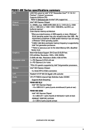
...to www.asus.com for Intel® CPU support list. Resolution: 2048 x 1536 @75Hz Expansion slots 1 x PCI Express 3.0*/2.0 x16 slot 2 x PCI Express 2.0 x1 slots *PCIe 3.0 speed is supported by Intel® 3rd generation processors. Supports Multi-Streaming USB P8H61-MX R2.0 Intel&#...174; H61 Express Chipset - 10 x USB 2.0/1.1 ports (4 ports at mid-board, 6 ports at rear) P8H61-MX USB3 Intel® H61 Express Chipset - 8 x USB 2.0/1.1 ports (4 ports at mid...
...to www.asus.com for Intel® CPU support list. Resolution: 2048 x 1536 @75Hz Expansion slots 1 x PCI Express 3.0*/2.0 x16 slot 2 x PCI Express 2.0 x1 slots *PCIe 3.0 speed is supported by Intel® 3rd generation processors. Supports Multi-Streaming USB P8H61-MX R2.0 Intel&#...174; H61 Express Chipset - 10 x USB 2.0/1.1 ports (4 ports at mid-board, 6 ports at rear) P8H61-MX USB3 Intel® H61 Express Chipset - 8 x USB 2.0/1.1 ports (4 ports at mid...
P8H61-MX R2.0 User's Manual
Page 10
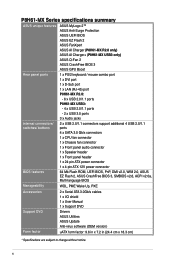
P8H61-MX Series specifications summary ASUS unique features ASUS MyLogo 2™ ASUS Anti-Surge Protection ASUS UEFI BIOS ASUS EZ Flash 2 ASUS FanXpert ASUS AI Charger (P8H61-MX R2.0 only) ASUS AI Charger+ (P8H61-MX USB3 only) ASUS Q-Fan 2 ASUS CrashFree BIOS 3 ASUS GPU Boost Rear panel ports 1 x PS/2 keyboard / mouse combo port 1 x DVI port 1 x D-Sub port 1 x LAN (RJ-45) port P8H61-MX R2.0: - 6 x USB 2.0/1.1 ports P8H61-MX...1 x I/O shield 1 x User Manual 1 x Support DVD Support DVD Drivers ASUS Utilities ASUS Update Anti-virus software (OEM version) Form factor uATX form factor: 9.6 in...
P8H61-MX Series specifications summary ASUS unique features ASUS MyLogo 2™ ASUS Anti-Surge Protection ASUS UEFI BIOS ASUS EZ Flash 2 ASUS FanXpert ASUS AI Charger (P8H61-MX R2.0 only) ASUS AI Charger+ (P8H61-MX USB3 only) ASUS Q-Fan 2 ASUS CrashFree BIOS 3 ASUS GPU Boost Rear panel ports 1 x PS/2 keyboard / mouse combo port 1 x DVI port 1 x D-Sub port 1 x LAN (RJ-45) port P8H61-MX R2.0: - 6 x USB 2.0/1.1 ports P8H61-MX...1 x I/O shield 1 x User Manual 1 x Support DVD Support DVD Drivers ASUS Utilities ASUS Update Anti-virus software (OEM version) Form factor uATX form factor: 9.6 in...
P8H61-MX R2.0 User's Manual
Page 11
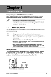
...removing or plugging in soft-off or the power cord is detached from the power supply. P8H61-MX R2.0 SB_PWR ON OFF Standby Power Powered Off P8H61-MX Series Onboard LED Chapter 1: Product introduction 1-1 The layout varies between the two models. ... for buying an ASUS® P8H61-MX Series motherboard! Refer to the motherboard, peripherals, or components. Chapter 1 Product introduction Thank you uninstall any component, place it on a grounded antistatic pad or in your retailer. • ASUS P8H61-MX Series motherboards include P8H61-MX R2.0 and P8H61-MX USB3 models.
...removing or plugging in soft-off or the power cord is detached from the power supply. P8H61-MX R2.0 SB_PWR ON OFF Standby Power Powered Off P8H61-MX Series Onboard LED Chapter 1: Product introduction 1-1 The layout varies between the two models. ... for buying an ASUS® P8H61-MX Series motherboard! Refer to the motherboard, peripherals, or components. Chapter 1 Product introduction Thank you uninstall any component, place it on a grounded antistatic pad or in your retailer. • ASUS P8H61-MX Series motherboards include P8H61-MX R2.0 and P8H61-MX USB3 models.
P8H61-MX R2.0 User's Manual
Page 12
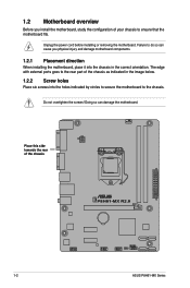
... or removing the motherboard. Doing so can cause you install the motherboard, study the configuration of your chassis to the rear part of the chassis P8H61-MX R2.0 1-2 ASUS P8H61-MX Series Failure to do so can damage the motherboard. Do not overtighten the screws! 1.2 Motherboard overview Before you physical injury and damage motherboard components. 1.2.1 Placement...
... or removing the motherboard. Doing so can cause you install the motherboard, study the configuration of your chassis to the rear part of the chassis P8H61-MX R2.0 1-2 ASUS P8H61-MX Series Failure to do so can damage the motherboard. Do not overtighten the screws! 1.2 Motherboard overview Before you physical injury and damage motherboard components. 1.2.1 Placement...
P8H61-MX R2.0 User's Manual
Page 15
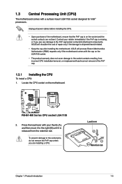
ASUS will shoulder the cost of repair only if the damage is shipment/transit-related. • Keep the cap after installing the motherboard. P8H61-MX R2.0 P8H61-MX Series CPU socket LGA1155 2. 1.3 Central Processing Unit (CPU) The motherboard comes with your retailer immediately if the PnP cap is... all power cables before installing the CPU. • Upon purchase of the PnP cap. 1.3.1 Installing the CPU To install a CPU: 1. ASUS will process Return Merchandise Authorization (RMA) requests only if the motherboard comes with the cap on the LGA1155 socket. • The product warranty does...
ASUS will shoulder the cost of repair only if the damage is shipment/transit-related. • Keep the cap after installing the motherboard. P8H61-MX R2.0 P8H61-MX Series CPU socket LGA1155 2. 1.3 Central Processing Unit (CPU) The motherboard comes with your retailer immediately if the PnP cap is... all power cables before installing the CPU. • Upon purchase of the PnP cap. 1.3.1 Installing the CPU To install a CPU: 1. ASUS will process Return Merchandise Authorization (RMA) requests only if the motherboard comes with the cap on the LGA1155 socket. • The product warranty does...
P8H61-MX R2.0 User's Manual
Page 19
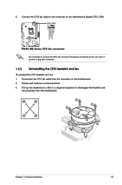
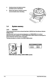
Rotate each fastener counterclockwise. 3. CPU_FAN CPU FAN PWM CPU FAN IN CPU FAN PWR GND P8H61-MX R2.0 P8H61-MX Series CPU fan connector Do not forget to plug this connector. 1.3.3 Uninstalling the CPU heatsink and fan To uninstall the CPU heatsink and fan: 1. Pull ...
Rotate each fastener counterclockwise. 3. CPU_FAN CPU FAN PWM CPU FAN IN CPU FAN PWR GND P8H61-MX R2.0 P8H61-MX Series CPU fan connector Do not forget to plug this connector. 1.3.3 Uninstalling the CPU heatsink and fan To uninstall the CPU heatsink and fan: 1. Pull ...
P8H61-MX R2.0 User's Manual
Page 20
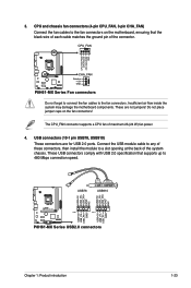
... performance with two Double Data Rate 3 (DDR3) Dual Inline Memory Modules (DIMM) sockets. The figure illustrates the location of the DDR3 DIMM sockets: DIMM_A1 DIMM_B1 P8H61-MX R2.0 Channel Channel A Channel B Sockets DIMM_A1 DIMM_B1 P8H61-MX Series 240-pin DDR3 DIMM sockets 1-10 ASUS P8H61-MX Series Rotate each fastener clockwise to prevent installation on a DDR2 DIMM socket.
... performance with two Double Data Rate 3 (DDR3) Dual Inline Memory Modules (DIMM) sockets. The figure illustrates the location of the DDR3 DIMM sockets: DIMM_A1 DIMM_B1 P8H61-MX R2.0 Channel Channel A Channel B Sockets DIMM_A1 DIMM_B1 P8H61-MX Series 240-pin DDR3 DIMM sockets 1-10 ASUS P8H61-MX Series Rotate each fastener clockwise to prevent installation on a DDR2 DIMM socket.
P8H61-MX R2.0 User's Manual
Page 29
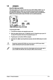
Keep the cap on CLRTC jumper default position. 1.6 Jumpers Clear RTC RAM (3-pin CLRTC) This jumper allows you to pins 2-3. P8H61-MX R2.0 CLRTC 12 23 Normal (Default) Clear RTC P8H61-MX Series Clear RTC RAM To erase the RTC RAM: 1. Move the jumper cap from pins 1-2 (default) to clear the Real Time Clock (RTC) RAM...
Keep the cap on CLRTC jumper default position. 1.6 Jumpers Clear RTC RAM (3-pin CLRTC) This jumper allows you to pins 2-3. P8H61-MX R2.0 CLRTC 12 23 Normal (Default) Clear RTC P8H61-MX Series Clear RTC RAM To erase the RTC RAM: 1. Move the jumper cap from pins 1-2 (default) to clear the Real Time Clock (RTC) RAM...
P8H61-MX R2.0 User's Manual
Page 31
... NC AAFP PIN 1 MIC2 MICPWR Line out_R NC Line out_L PORT1 L PORT1 R PORT2 R SENSE_SEND PORT2 L P8H61-MX R2.0 HD-audio-compliant Legacy AC'97 pin definition compliant definition P8H61-MX Series Front panel audio connector Chapter 1: Product introduction 1-21 D-Sub port. DVI-D port. USB 2.0 ports ...We strongly recommend that supports either HD Audio or legacy AC`97 audio standard. USB 2.0 ports 1 and 2. USB 2.0 ports 3 and 4 (P8H61-MX R2.0 only). These two 9-pin Universal Serial Bus (USB) ports are for USB 2.0/1.1 devices. 7. Front panel audio connector (10-1 pin AAFP) This...
... NC AAFP PIN 1 MIC2 MICPWR Line out_R NC Line out_L PORT1 L PORT1 R PORT2 R SENSE_SEND PORT2 L P8H61-MX R2.0 HD-audio-compliant Legacy AC'97 pin definition compliant definition P8H61-MX Series Front panel audio connector Chapter 1: Product introduction 1-21 D-Sub port. DVI-D port. USB 2.0 ports ...We strongly recommend that supports either HD Audio or legacy AC`97 audio standard. USB 2.0 ports 1 and 2. USB 2.0 ports 3 and 4 (P8H61-MX R2.0 only). These two 9-pin Universal Serial Bus (USB) ports are for USB 2.0/1.1 devices. 7. Front panel audio connector (10-1 pin AAFP) This...

P8H61-MX R2.0 User's Manual
Page 32
EATX12V EATXPWR +12V DC +12V DC P8H61-MX R2.0 GND GND +3 Volts +12 Volts +12 Volts +5V Standby Power OK PIN 1 GND +5 Volts GND +5 Volts GND +3 Volts +3 Volts PIN 1 P8H61-MX Series ATX power connectors GND +5 Volts +5 Volts +5 Volts -5 Volts GND GND GND PSON# GND -12 Volts +3 Volts &#...are uncertain about the minimum power supply requirement for ATX power supply plugs. See section 2.5.6 Onboard Devices Configuration for details. 1-22 ASUS P8H61-MX Series By default, this connector, set the item to fit these connectors in the BIOS setup to [HD]. Find the proper...
EATX12V EATXPWR +12V DC +12V DC P8H61-MX R2.0 GND GND +3 Volts +12 Volts +12 Volts +5V Standby Power OK PIN 1 GND +5 Volts GND +5 Volts GND +3 Volts +3 Volts PIN 1 P8H61-MX Series ATX power connectors GND +5 Volts +5 Volts +5 Volts -5 Volts GND GND GND PSON# GND -12 Volts +3 Volts &#...are uncertain about the minimum power supply requirement for ATX power supply plugs. See section 2.5.6 Onboard Devices Configuration for details. 1-22 ASUS P8H61-MX Series By default, this connector, set the item to fit these connectors in the BIOS setup to [HD]. Find the proper...
P8H61-MX R2.0 User's Manual
Page 33
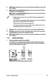
...system chassis. USB+5V USB_P6USB_P6+ GND NC USB+5V USB_P8USB_P8+ GND NC USB78 USB910 USB+5V USB_P5USB_P5+ GND USB+5V USB_P7USB_P7+ GND P8H61-MX R2.0 PIN 1 PIN 1 P8H61-MX Series USB2.0 connectors Chapter 1: Product introduction 1-23 Do not place jumper caps on the motherboard, ensuring that supports up to a ...pin CHA_FAN) Connect the fan cables to the fan connectors. CPU_FAN CPU FAN PWM CPU FAN IN CPU FAN PWR GND P8H61-MX R2.0 CHA_FAN Rotation +12V GND P8H61-MX Series Fan connectors Do not forget to connect the fan cables to the fan connectors on the fan connectors! These USB...
...system chassis. USB+5V USB_P6USB_P6+ GND NC USB+5V USB_P8USB_P8+ GND NC USB78 USB910 USB+5V USB_P5USB_P5+ GND USB+5V USB_P7USB_P7+ GND P8H61-MX R2.0 PIN 1 PIN 1 P8H61-MX Series USB2.0 connectors Chapter 1: Product introduction 1-23 Do not place jumper caps on the motherboard, ensuring that supports up to a ...pin CHA_FAN) Connect the fan cables to the fan connectors. CPU_FAN CPU FAN PWM CPU FAN IN CPU FAN PWR GND P8H61-MX R2.0 CHA_FAN Rotation +12V GND P8H61-MX Series Fan connectors Do not forget to connect the fan cables to the fan connectors on the fan connectors! These USB...
P8H61-MX R2.0 User's Manual
Page 34
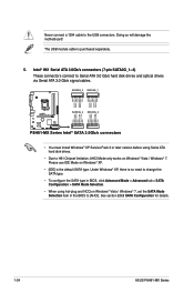
See section 2.5.3 SATA Configuration for details. 1-24 ASUS P8H61-MX Series Intel® H61 Serial ATA 3.0Gb/s connectors (7-pin SATA3G_1~4) These connectors connect to the USB connectors. Doing so will damage.... SATA3G_3 SATA3G_1 GND RSATA_TXP3 RSATA_TXN3 GND RSATA_RXN3 RSATA_RXP3 GND GND RSATA_TXP1 RSATA_TXN1 GND RSATA_RXN1 RSATA_RXP1 GND P8H61-MX R2.0 SATA3G_4 SATA3G_2 GND RSATA_RXP4 RSATA_RXN4 GND RSATA_TXN4 RSATA_TXP4 GND GND RSATA_RXP2 RSATA_RXN2 GND RSATA_TXN2 RSATA_TXP2 GND P8H61-MX Series Intel® SATA 3.0Gb/s connectors • You must install Windows® XP Service...
See section 2.5.3 SATA Configuration for details. 1-24 ASUS P8H61-MX Series Intel® H61 Serial ATA 3.0Gb/s connectors (7-pin SATA3G_1~4) These connectors connect to the USB connectors. Doing so will damage.... SATA3G_3 SATA3G_1 GND RSATA_TXP3 RSATA_TXN3 GND RSATA_RXN3 RSATA_RXP3 GND GND RSATA_TXP1 RSATA_TXN1 GND RSATA_RXN1 RSATA_RXP1 GND P8H61-MX R2.0 SATA3G_4 SATA3G_2 GND RSATA_RXP4 RSATA_RXN4 GND RSATA_TXN4 RSATA_TXP4 GND GND RSATA_RXP2 RSATA_RXN2 GND RSATA_TXN2 RSATA_TXP2 GND P8H61-MX Series Intel® SATA 3.0Gb/s connectors • You must install Windows® XP Service...
P8H61-MX R2.0 User's Manual
Page 35
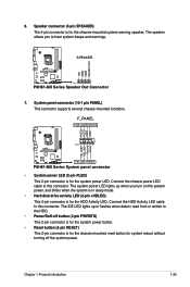
System panel connector (10-1 pin PANEL) This connector supports several chassis-mounted functions. Ground Reset P8H61-MX R2.0 PIN 1 +HD_LED RESET P8H61-MX Series System panel connector • System power LED (2-pin PLED) This 2-pin connector is for the chassis-mounted system warning speaker. Connect the chassis power ... disk drive activity LED (2-pin +HDLED) This 2-pin connector is read from or written to hear system beeps and warnings. +5V GND GND Speaker Out P8H61-MX R2.0 SPEAKER PIN 1 P8H61-MX Series Speaker Out Connector 7. 6.
System panel connector (10-1 pin PANEL) This connector supports several chassis-mounted functions. Ground Reset P8H61-MX R2.0 PIN 1 +HD_LED RESET P8H61-MX Series System panel connector • System power LED (2-pin PLED) This 2-pin connector is for the chassis-mounted system warning speaker. Connect the chassis power ... disk drive activity LED (2-pin +HDLED) This 2-pin connector is read from or written to hear system beeps and warnings. +5V GND GND Speaker Out P8H61-MX R2.0 SPEAKER PIN 1 P8H61-MX Series Speaker Out Connector 7. 6.
P8H61-MX R2.0 User's Manual
Page 38
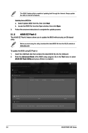
...Info 03/13/12 10:23p 4194304 Exit DATE: 03/14/2012 P8H61-MX-R2-SI-0401.ROM File Info MODEL: Help Info VER: DATE [Enter] Select or Load [Tab] Switch [Up/Down/PageUp/PageDown/Home/End] Move [Esc] Exit 2-2 ASUS P8H61-MX Series Insert the USB flash disk that contains the latest BIOS file... into the USB port. 2. Go to the Tool menu to select ASUS EZ Flash Utility and press to avail all its features. Select Update BIOS from...
...Info 03/13/12 10:23p 4194304 Exit DATE: 03/14/2012 P8H61-MX-R2-SI-0401.ROM File Info MODEL: Help Info VER: DATE [Enter] Select or Load [Tab] Switch [Up/Down/PageUp/PageDown/Home/End] Move [Esc] Exit 2-2 ASUS P8H61-MX Series Insert the USB flash disk that contains the latest BIOS file... into the USB port. 2. Go to the Tool menu to select ASUS EZ Flash Utility and press to avail all its features. Select Update BIOS from...
P8H61-MX R2.0 User's Manual
Page 40
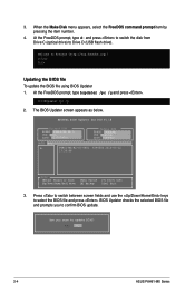
... Updater screen appears as below. ASUSTek BIOS Updater for DOS V1.18 Current ROM BOARD: P8H61-MX R2.0 VER: 0401 DATE: 02/16/2012 Update ROM BOARD: Unknown VER: Unknown DATE: Unknown PATH: A:\ A: P8H61-MX-R2-SI-0401 4194304 2012-03-12 17:30:48 Note [Enter] Select or Load [Up...item number. 4. Press to switch between screen fields and use the keys to FreeDOS (http://www.freedos.org)! D:\>bupdater /pc /g 2. 3. Yes No 2-4 ASUS P8H61-MX Series Welcome to select the BIOS file and press . At the FreeDOS prompt, type bupdater /pc /g and press . At the FreeDOS prompt, type d: ...
... Updater screen appears as below. ASUSTek BIOS Updater for DOS V1.18 Current ROM BOARD: P8H61-MX R2.0 VER: 0401 DATE: 02/16/2012 Update ROM BOARD: Unknown VER: Unknown DATE: Unknown PATH: A:\ A: P8H61-MX-R2-SI-0401 4194304 2012-03-12 17:30:48 Note [Enter] Select or Load [Up...item number. 4. Press to switch between screen fields and use the keys to FreeDOS (http://www.freedos.org)! D:\>bupdater /pc /g 2. 3. Yes No 2-4 ASUS P8H61-MX Series Welcome to select the BIOS file and press . At the FreeDOS prompt, type bupdater /pc /g and press . At the FreeDOS prompt, type d: ...
P8H61-MX R2.0 User's Manual
Page 68
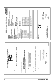
No. 150, LI-TE RD., PEITOU, TAIPEI 112, TAIWAN R.O.C. Country: TAIWAN Authorized representative in Europe: ASUS COMPUTER GmbH Address, City: HARKORT STR. 21-23, 40880 RATINGEN Country: GERMANY declare the following apparatus: Product name : Motherboard Model name : P8H61-MX R2.0, P8H61-MX USB3 conform with part 15 of the following directives: 2004/108/EC-EMC Directive EN...
No. 150, LI-TE RD., PEITOU, TAIPEI 112, TAIWAN R.O.C. Country: TAIWAN Authorized representative in Europe: ASUS COMPUTER GmbH Address, City: HARKORT STR. 21-23, 40880 RATINGEN Country: GERMANY declare the following apparatus: Product name : Motherboard Model name : P8H61-MX R2.0, P8H61-MX USB3 conform with part 15 of the following directives: 2004/108/EC-EMC Directive EN...


