
User Manual
Page 11
...motherboard component. Refer to the motherboard, peripherals, or components. Failure to do so may cause severe damage to page x for buying an ASUS® P8H61-M2 USB3 motherboard! The illustration below shows the location of accessories. Before you uninstall any of the following precautions before you install motherboard components or ...component, place it , check the items in soft-off or the power cord is damaged or missing, contact your motherboard package. SB_PWR P8H61-M2 USB3 ON OFF Standby Power Powered Off P8H61-M2 USB3 Onboard LED Chapter 1: Product introduction 1-1
...motherboard component. Refer to the motherboard, peripherals, or components. Failure to do so may cause severe damage to page x for buying an ASUS® P8H61-M2 USB3 motherboard! The illustration below shows the location of accessories. Before you uninstall any of the following precautions before you install motherboard components or ...component, place it , check the items in soft-off or the power cord is damaged or missing, contact your motherboard package. SB_PWR P8H61-M2 USB3 ON OFF Standby Power Powered Off P8H61-M2 USB3 Onboard LED Chapter 1: Product introduction 1-1

User Manual
Page 12
... chassis in the image below. 1.2.2 Screw holes Place six screws into it. The edge with external ports goes to the rear part of the chassis P8H61-M2 USB3 1-2 ASUS P8H61-M2 USB3 Place this side towards the rear of the chassis as indicated in the correct orientation. Do not overtighten the screws! Doing so can cause you...
... chassis in the image below. 1.2.2 Screw holes Place six screws into it. The edge with external ports goes to the rear part of the chassis P8H61-M2 USB3 1-2 ASUS P8H61-M2 USB3 Place this side towards the rear of the chassis as indicated in the correct orientation. Do not overtighten the screws! Doing so can cause you...

User Manual
Page 14
... Return Merchandise Authorization (RMA) requests only if the motherboard comes with the cap on the motherboard. P8H61-M2 USB3 P8H61-M2 USB3 CPU socket LGA1155 2. ASUS will shoulder the cost of repair only if the damage is on the socket and the socket contacts are ...you see any damage to the right (B) until it to the PnP cap/socket contacts/motherboard components. Load lever A B Retention tab 1-4 ASUS P8H61-M2 USB3 1.3 Central Processing Unit (CPU) The motherboard comes with your retailer immediately if the PnP cap is released from incorrect CPU installation/removal, ...
... Return Merchandise Authorization (RMA) requests only if the motherboard comes with the cap on the motherboard. P8H61-M2 USB3 P8H61-M2 USB3 CPU socket LGA1155 2. ASUS will shoulder the cost of repair only if the damage is on the socket and the socket contacts are ...you see any damage to the right (B) until it to the PnP cap/socket contacts/motherboard components. Load lever A B Retention tab 1-4 ASUS P8H61-M2 USB3 1.3 Central Processing Unit (CPU) The motherboard comes with your retailer immediately if the PnP cap is released from incorrect CPU installation/removal, ...

User Manual
Page 16
... off immediately, and seek professional medical help. 7. B A C 8. Apply some Thermal Interface Material to the exposed area of the load plate slides under the retention tab. 1-6 ASUS P8H61-M2 USB3
... off immediately, and seek professional medical help. 7. B A C 8. Apply some Thermal Interface Material to the exposed area of the load plate slides under the retention tab. 1-6 ASUS P8H61-M2 USB3
User Manual
Page 18
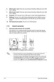
Disconnect the CPU fan cable from the motherboard. CPU_FAN CPU FAN PWM CPU FAN IN CPU FAN PWR GND P8H61-M2 USB3 P8H61-M2 USB3 CPU fan connector Do not forget to disengage the heatsink and fan assembly from the connector on the motherboard labeled CPU_FAN. Rotate each fastener counterclockwise. 3. ... on the motherboard. 2. Connect the CPU fan cable to plug this connector. 1.3.3 Uninstalling the CPU heatsink and fan To uninstall the CPU heatsink and fan: 1. A B A B B A B A 1-8 ASUS P8H61-M2 USB3 3.
Disconnect the CPU fan cable from the motherboard. CPU_FAN CPU FAN PWM CPU FAN IN CPU FAN PWR GND P8H61-M2 USB3 P8H61-M2 USB3 CPU fan connector Do not forget to disengage the heatsink and fan assembly from the connector on the motherboard labeled CPU_FAN. Rotate each fastener counterclockwise. 3. ... on the motherboard. 2. Connect the CPU fan cable to plug this connector. 1.3.3 Uninstalling the CPU heatsink and fan To uninstall the CPU heatsink and fan: 1. A B A B B A B A 1-8 ASUS P8H61-M2 USB3 3.

User Manual
Page 20
...DIMM 2 DIMM • • • • • • • • • • • • 1-10 ASUS P8H61-M2 USB3 For optimum compatibility, we recommend that you install 4GB or more efficient memory cooling system to support a full memory load (2 DIMMs) or overclocking condition. For...available in Channel A and Channel B. Under the default state, some memory modules for the dual-channel configuration. P8H61-M2 USB3 Motherboard Qualified Vendors Lists (QVL) DDR3-1066 MHz capability Vendors Crucial Crucial ELPIDA ELPIDA KINGSTON KINGSTON Part No. The...
...DIMM 2 DIMM • • • • • • • • • • • • 1-10 ASUS P8H61-M2 USB3 For optimum compatibility, we recommend that you install 4GB or more efficient memory cooling system to support a full memory load (2 DIMMs) or overclocking condition. For...available in Channel A and Channel B. Under the default state, some memory modules for the dual-channel configuration. P8H61-M2 USB3 Motherboard Qualified Vendors Lists (QVL) DDR3-1066 MHz capability Vendors Crucial Crucial ELPIDA ELPIDA KINGSTON KINGSTON Part No. The...
User Manual
Page 22
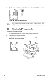
... 1 1 Unlocked retaining clip DIMM slot key A DIMM is properly seated. The DIMM might get damaged when it fits in only one direction. DIMM notch 1-12 ASUS P8H61-M2 USB3 Failure to do so can cause severe damage to unlock a DIMM socket. 2. Simultaneously press the retaining clips outward to avoid damaging the DIMM. 3. Press the...
... 1 1 Unlocked retaining clip DIMM slot key A DIMM is properly seated. The DIMM might get damaged when it fits in only one direction. DIMM notch 1-12 ASUS P8H61-M2 USB3 Failure to do so can cause severe damage to unlock a DIMM socket. 2. Simultaneously press the retaining clips outward to avoid damaging the DIMM. 3. Press the...

User Manual
Page 24
... and system setup parameters by erasing the CMOS RTC RAM data. Move the jumper cap from pins 1-2 (default) to default values. 1-14 ASUS P8H61-M2 USB3 Removing the cap will cause system boot failure! • If the steps above do not need to clear the RTC when the system hangs... CMOS RTC RAM data. Hold down and reboot the system, then the BIOS automatically resets parameter settings to pins 2-3. CLRTC P8H61-M2 USB3 12 23 Normal (Default) Clear RTC P8H61-M2 USB3 Clear RTC RAM To erase the RTC RAM: 1. Turn OFF the computer and unplug the power cord. 2. 1.6 Jumpers Clear...
... and system setup parameters by erasing the CMOS RTC RAM data. Move the jumper cap from pins 1-2 (default) to default values. 1-14 ASUS P8H61-M2 USB3 Removing the cap will cause system boot failure! • If the steps above do not need to clear the RTC when the system hangs... CMOS RTC RAM data. Hold down and reboot the system, then the BIOS automatically resets parameter settings to pins 2-3. CLRTC P8H61-M2 USB3 12 23 Normal (Default) Clear RTC P8H61-M2 USB3 Clear RTC RAM To erase the RTC RAM: 1. Turn OFF the computer and unplug the power cord. 2. 1.6 Jumpers Clear...
User Manual
Page 26
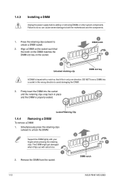
... are for USB 2.0/1.1 devices. 7. This port is for a High-Definition Multimedia Interface (HDMI) connector, and is for details. 1-16 ASUS P8H61-M2 USB3 PS/2 keyboard port (purple). Connect one end of HD DVD, Blu-ray, and other VGA-compatible devices. 9. See section 2.5.6 Onboard Devices... 1 MIC2 MICPWR Line out_R NC Line out_L PORT1 L PORT1 R PORT2 R SENSE_SEND PORT2 L P8H61-M2 USB3 HD-audio-compliant Legacy AC'97 pin definition compliant definition P8H61-M2 USB3 Front panel audio connector • We recommend that supports either HD Audio or legacy AC`97 audio...
... are for USB 2.0/1.1 devices. 7. This port is for a High-Definition Multimedia Interface (HDMI) connector, and is for details. 1-16 ASUS P8H61-M2 USB3 PS/2 keyboard port (purple). Connect one end of HD DVD, Blu-ray, and other VGA-compatible devices. 9. See section 2.5.6 Onboard Devices... 1 MIC2 MICPWR Line out_R NC Line out_L PORT1 L PORT1 R PORT2 R SENSE_SEND PORT2 L P8H61-M2 USB3 HD-audio-compliant Legacy AC'97 pin definition compliant definition P8H61-M2 USB3 Front panel audio connector • We recommend that supports either HD Audio or legacy AC`97 audio...

User Manual
Page 28
...and "Ground" are not jumpers! CHASSIS +5VSB_MB Chassis Signal GND P8H61-M2 USB3 P8H61-M2 USB3 Chassis intrusion connector 1-18 ASUS P8H61-M2 USB3 CPU_FAN CPU FAN PWM CPU FAN IN CPU FAN PWR GND P8H61-M2 USB3 CHA_FAN GND +12V Rotation P8H61-M2 USB3 fan connectors Do not forget to connect the fan cables to use...the fan connectors. Connect one end of maximum 2A (24 W) fan power. • Only the 4-pin CPU fan supports the ASUS Q-Fan 2 and FanXpert features. 4. Insufficient air flow inside the system may damage the motherboard components. Chassis intrusion connector (4-1 pin ...
...and "Ground" are not jumpers! CHASSIS +5VSB_MB Chassis Signal GND P8H61-M2 USB3 P8H61-M2 USB3 Chassis intrusion connector 1-18 ASUS P8H61-M2 USB3 CPU_FAN CPU FAN PWM CPU FAN IN CPU FAN PWR GND P8H61-M2 USB3 CHA_FAN GND +12V Rotation P8H61-M2 USB3 fan connectors Do not forget to connect the fan cables to use...the fan connectors. Connect one end of maximum 2A (24 W) fan power. • Only the 4-pin CPU fan supports the ASUS Q-Fan 2 and FanXpert features. 4. Insufficient air flow inside the system may damage the motherboard components. Chassis intrusion connector (4-1 pin ...
User Manual
Page 30
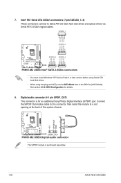
... drives via Serial ATA 3.0 Gb/s signal cables. 7. Digital audio connector (4-1 pin SPDIF_OUT) This connector is purchased separately. 1-20 ASUS P8H61-M2 USB3 Intel® H61 Serial ATA 3.0Gb/s connectors (7-pin SATA3G_1~4) These connectors connect to a slot opening at the back of the system... RSATA_RXN2 GND RSATA_TXN2 RSATA_TXP2 GND GND RSATA_RXP4 RSATA_RXN4 GND RSATA_TXN4 RSATA_TXP4 GND GND RSATA_RXP3 RSATA_RXN3 GND RSATA_TXN3 RSATA_TXP3 GND P8H61-M2 USB3 SATA3G_4 SATA3G_3 P8H61-M2 USB3 Intel® SATA 3.0Gb/s connectors • You must install Windows® XP Service Pack 3 or ...
... drives via Serial ATA 3.0 Gb/s signal cables. 7. Digital audio connector (4-1 pin SPDIF_OUT) This connector is purchased separately. 1-20 ASUS P8H61-M2 USB3 Intel® H61 Serial ATA 3.0Gb/s connectors (7-pin SATA3G_1~4) These connectors connect to a slot opening at the back of the system... RSATA_RXN2 GND RSATA_TXN2 RSATA_TXP2 GND GND RSATA_RXP4 RSATA_RXN4 GND RSATA_TXN4 RSATA_TXP4 GND GND RSATA_RXP3 RSATA_RXN3 GND RSATA_TXN3 RSATA_TXP3 GND P8H61-M2 USB3 SATA3G_4 SATA3G_3 P8H61-M2 USB3 Intel® SATA 3.0Gb/s connectors • You must install Windows® XP Service Pack 3 or ...

User Manual
Page 32
...vary. The contents of your OS documentation for detailed information. • Ensure that you can install to change at www.asus.com for updates. Visit the ASUS website at any time without notice. If Autorun is for better compatibility and system stability. 1.8.2 Support DVD information The ... the latest OS version and corresponding updates to locate the file ASSETUP.EXE from the BIN folder. To run the DVD. 1-22 ASUS P8H61-M2 USB3 Double-click the ASSETUP.EXE to display their respective menus. The following screen is enabled in your computer, the DVD automatically displays the...
...vary. The contents of your OS documentation for detailed information. • Ensure that you can install to change at www.asus.com for updates. Visit the ASUS website at any time without notice. If Autorun is for better compatibility and system stability. 1.8.2 Support DVD information The ... the latest OS version and corresponding updates to locate the file ASSETUP.EXE from the BIN folder. To run the DVD. 1-22 ASUS P8H61-M2 USB3 Double-click the ASSETUP.EXE to display their respective menus. The following screen is enabled in your computer, the DVD automatically displays the...
User Manual
Page 34
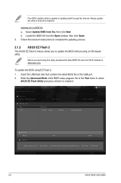
... USB flash disk that contains the latest BIOS file to avail all its features. Select Update BIOS from the ASUS website at www.asus.com. ASUS EZ Flash 2 Utility V01.04 Flash Info MODEL: P8H61-M2 USB3 File Path: fs0:\ Drive fs0:\ VER: 0203 Folder Info 01/13/11 10:23p 4194304 Exit DATE: 12/06....ROM File Info MODEL: Help Info VER: DATE [Enter] Select or Load [Tab] Switch [Up/Down/PageUp/PageDown/Home/End] Move [Esc] Exit [F2] Backup 2-2 ASUS P8H61-M2 USB3 To update the BIOS using an OS‑based utility. Always update the utility to the USB port. 2. The...
... USB flash disk that contains the latest BIOS file to avail all its features. Select Update BIOS from the ASUS website at www.asus.com. ASUS EZ Flash 2 Utility V01.04 Flash Info MODEL: P8H61-M2 USB3 File Path: fs0:\ Drive fs0:\ VER: 0203 Folder Info 01/13/11 10:23p 4194304 Exit DATE: 12/06....ROM File Info MODEL: Help Info VER: DATE [Enter] Select or Load [Tab] Switch [Up/Down/PageUp/PageDown/Home/End] Move [Esc] Exit [F2] Backup 2-2 ASUS P8H61-M2 USB3 To update the BIOS using an OS‑based utility. Always update the utility to the USB port. 2. The...

User Manual
Page 36
...At the FreeDOS prompt, type d: and press to switch the disk from the ASUS website at http://support.asus.com and save the BIOS file and BIOS Updater to show the BIOS Boot Device Select Menu. C:\>d: D:\> 2-4 ASUS P8H61-M2 USB3 Insert the USB flash drive with the latest BIOS file and BIOS Updater to ...to update BIOS in NTFS format. 3. Download the latest BIOS file and BIOS Updater from Drive C (optical drive) to the USB port. 2. 2.1.4 ASUS BIOS Updater The ASUS BIOS Updater allows you can use as a backup when the BIOS fails or gets corrupted during the updating process. When the...
...At the FreeDOS prompt, type d: and press to switch the disk from the ASUS website at http://support.asus.com and save the BIOS file and BIOS Updater to show the BIOS Boot Device Select Menu. C:\>d: D:\> 2-4 ASUS P8H61-M2 USB3 Insert the USB flash drive with the latest BIOS file and BIOS Updater to ...to update BIOS in NTFS format. 3. Download the latest BIOS file and BIOS Updater from Drive C (optical drive) to the USB port. 2. 2.1.4 ASUS BIOS Updater The ASUS BIOS Updater allows you can use as a backup when the BIOS fails or gets corrupted during the updating process. When the...

User Manual
Page 38
... Yes No 4. Select the Load Optimized Defaults item under the Exit menu. Refer to section 2.9 Exit menu for DOS V1.18 Current ROM BOARD: P8H61-M2 USB3 VER: 0203 DATE: 12/06/2011 Update ROM BOARD: Unknown VER: Unknown DATE: Unknown PATH: A:\ A: H61M2USB.ROM 4194304 2011-01-11 17:... drives after updating BIOS. • Ensure to load the BIOS default settings to confirm BIOS update. Are you have disconnected them. 2-6 ASUS P8H61-M2 USB3 When BIOS update is done, press to update BIOS? D:\>bupdater /pc /g 2. At the FreeDOS prompt, type bupdater /pc /g and press .
... Yes No 4. Select the Load Optimized Defaults item under the Exit menu. Refer to section 2.9 Exit menu for DOS V1.18 Current ROM BOARD: P8H61-M2 USB3 VER: 0203 DATE: 12/06/2011 Update ROM BOARD: Unknown VER: Unknown DATE: Unknown PATH: A:\ A: H61M2USB.ROM 4194304 2011-01-11 17:... drives after updating BIOS. • Ensure to load the BIOS default settings to confirm BIOS update. Are you have disconnected them. 2-6 ASUS P8H61-M2 USB3 When BIOS update is done, press to update BIOS? D:\>bupdater /pc /g 2. At the FreeDOS prompt, type bupdater /pc /g and press .

User Manual
Page 40
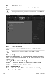
To access the Advanced Mode, click Exit/Advanced Mode, then select Advanced Mode. EZ Mode Friday [10/08/2010] P8H61-M2 USB3 BIOS Version : 0203 CPU Type : Intel(R) Core(TM) i5-2400 CPU @ 3.30GHz Total Memory : 1024 MB (DDR3 1333MHz) Build Date : 12/06/2011 Speed : 3300 ... used under two modes: EZ Mode and Advanced Mode. The EZ Mode provides you an overview of the BIOS setup program Clicks to the system. 2-8 ASUS P8H61-M2 USB3 Refer to decide the boot priority. BIOS menu screen The BIOS setup program can be changed.
To access the Advanced Mode, click Exit/Advanced Mode, then select Advanced Mode. EZ Mode Friday [10/08/2010] P8H61-M2 USB3 BIOS Version : 0203 CPU Type : Intel(R) Core(TM) i5-2400 CPU @ 3.30GHz Total Memory : 1024 MB (DDR3 1333MHz) Build Date : 12/06/2011 Speed : 3300 ... used under two modes: EZ Mode and Advanced Mode. The EZ Mode provides you an overview of the BIOS setup program Clicks to the system. 2-8 ASUS P8H61-M2 USB3 Refer to decide the boot priority. BIOS menu screen The BIOS setup program can be changed.
User Manual
Page 42
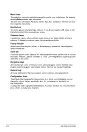
... BIOS setup program. General help At the top right corner of the menu screen is user-configurable, you can change the value of options. 2-10 ASUS P8H61-M2 USB3 Press or use the USB mouse to click this button to return to display a list of the field opposite the item. For example, selecting Main...
... BIOS setup program. General help At the top right corner of the menu screen is user-configurable, you can change the value of options. 2-10 ASUS P8H61-M2 USB3 Press or use the USB mouse to click this button to return to display a list of the field opposite the item. For example, selecting Main...
User Manual
Page 44
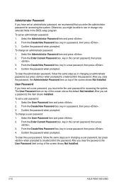
..., then press . 4. Confirm the password when prompted. After you clear the password, the Administrator Password item on top of the screen shows Not Installed. 2-12 ASUS P8H61-M2 USB3 To clear the user password, follow the same steps as in the BIOS setup program. Otherwise, you clear the password, the User Password item on...
..., then press . 4. Confirm the password when prompted. After you clear the password, the Administrator Password item on top of the screen shows Not Installed. 2-12 ASUS P8H61-M2 USB3 To clear the user password, follow the same steps as in the BIOS setup program. Otherwise, you clear the password, the User Password item on...

User Manual
Page 46
... allow you to 32, which may cause the system to adjust the value. Enhanced Intel SpeedStep Technology [Enabled] Allows you to adjust the value. 2-14 ASUS P8H61-M2 USB3 Any under 255 can be kept a time duration exceed TDP for extreme graphics performance. For Sandy Bridge, Turbo Ratio can vary from 1 to enable or...
... allow you to 32, which may cause the system to adjust the value. Enhanced Intel SpeedStep Technology [Enabled] Allows you to adjust the value. 2-14 ASUS P8H61-M2 USB3 Any under 255 can be kept a time duration exceed TDP for extreme graphics performance. For Sandy Bridge, Turbo Ratio can vary from 1 to enable or...
User Manual
Page 48
... system devices. Intel Adaptive Thermal Monitor [Enabled] [Enabled] Enables the overheated CPU to throttle its clock speed to your CPU model. Configuration options: [All] [1] [2] [3] 2-16 ASUS P8H61-M2 USB3 2.5 Advanced menu The Advanced menu items allow you to set the ratio between the CPU Core Clock and the BCLK Frequency. EFI BIOS Utility - The...
... system devices. Intel Adaptive Thermal Monitor [Enabled] [Enabled] Enables the overheated CPU to throttle its clock speed to your CPU model. Configuration options: [All] [1] [2] [3] 2-16 ASUS P8H61-M2 USB3 2.5 Advanced menu The Advanced menu items allow you to set the ratio between the CPU Core Clock and the BCLK Frequency. EFI BIOS Utility - The...


