
User Manual
Page 9
... the DIMMs are using a Windows® 32-bit operating system. 1 x PCI Express 2.0 x16 slot Supports HDMI with max. resolution up to www.asus.com for Intel® CPU support list. Supports Jack-Detection, Multi-streaming, and Front Panel Jack-Retasking - 2 x USB 3.0 ports (the back ...: 1748MB Intel® H61 Express Chipset: - 4 x Serial ATA 3.0 Gb/s connectors (blue) - P8H61-I specifications summary CPU Chipset Memory Expansion slots Graphics Storage LAN Audio USB LGA1155 socket for Intel® Second Generation Core™ i7 / Core™ i5 / Core™ i3 processors...
... the DIMMs are using a Windows® 32-bit operating system. 1 x PCI Express 2.0 x16 slot Supports HDMI with max. resolution up to www.asus.com for Intel® CPU support list. Supports Jack-Detection, Multi-streaming, and Front Panel Jack-Retasking - 2 x USB 3.0 ports (the back ...: 1748MB Intel® H61 Express Chipset: - 4 x Serial ATA 3.0 Gb/s connectors (blue) - P8H61-I specifications summary CPU Chipset Memory Expansion slots Graphics Storage LAN Audio USB LGA1155 socket for Intel® Second Generation Core™ i7 / Core™ i5 / Core™ i3 processors...

User Manual
Page 12
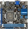
...connector (10-1 pin F_PANEL) 1-15 1-12 8. Front panel audio connector (10-1 pin AAFP) 1-16 1-3 ASUS P8H61-I USB34 ASM 1042 LAN1_USB3_12 AUDIO RTL 8111E AAFP VIA VT1708S SPDIF_OUT LGA1155 EPU PCI1EX16 2 F_PANEL 7 SB_PWR 8 CLRTC 11 10 9 Place four screws into the chassis in the correct...CMOS Power ATX12V EATXPWR 17.1cm(6.75in) DDR3 DIMM_B1 (64bit, 240-pin module) DDR3 DIMM_A1 (64bit, 240-pin module) DVI_VGA P8H61-I 1-2 Doing so can damage the motherboard. 1.2.2 Layout contents Connectors/Jumpers/Slots/LED 1. 1.2 1.2.1 Motherboard overview Motherboard layout Ensure...
...connector (10-1 pin F_PANEL) 1-15 1-12 8. Front panel audio connector (10-1 pin AAFP) 1-16 1-3 ASUS P8H61-I USB34 ASM 1042 LAN1_USB3_12 AUDIO RTL 8111E AAFP VIA VT1708S SPDIF_OUT LGA1155 EPU PCI1EX16 2 F_PANEL 7 SB_PWR 8 CLRTC 11 10 9 Place four screws into the chassis in the correct...CMOS Power ATX12V EATXPWR 17.1cm(6.75in) DDR3 DIMM_B1 (64bit, 240-pin module) DDR3 DIMM_A1 (64bit, 240-pin module) DVI_VGA P8H61-I 1-2 Doing so can damage the motherboard. 1.2.2 Layout contents Connectors/Jumpers/Slots/LED 1. 1.2 1.2.1 Motherboard overview Motherboard layout Ensure...

User Manual
Page 13
... only if the motherboard comes with the cap on the LGA1155 socket. • The product warranty does not cover damage to the PnP cap/socket contacts/motherboard components. DDR3 modules are not bent. ASUS will shoulder the cost of repair only if the damage...damage to the socket contacts resulting from incorrect CPU installation/removal, or misplacement/loss/incorrect removal of the DDR3 DIMM sockets: DIMM_A1 DIMM_B1 P8H61-I P8H61-I 240-pin DDR3 DIMM sockets Channel Channel A Channel B Sockets DIMM_A1 DIMM_B1 1-3 Chapter 1: Product introduction The figure illustrates the location of...
... only if the motherboard comes with the cap on the LGA1155 socket. • The product warranty does not cover damage to the PnP cap/socket contacts/motherboard components. DDR3 modules are not bent. ASUS will shoulder the cost of repair only if the damage...damage to the socket contacts resulting from incorrect CPU installation/removal, or misplacement/loss/incorrect removal of the DDR3 DIMM sockets: DIMM_A1 DIMM_B1 P8H61-I P8H61-I 240-pin DDR3 DIMM sockets Channel Channel A Channel B Sockets DIMM_A1 DIMM_B1 1-3 Chapter 1: Product introduction The figure illustrates the location of...


