
User Manual
Page 4
... time 3-3 3.2 Powering off the computer 3-4 3.2.1 Using the OS shut down function 3-4 3.2.2 Using the dual function power switch 3-4 Chapter 4: BIOS setup 4.1 Managing and updating your BIOS 4-3 4.1.1 ASUS EZ Flash 2 utility 4-3 4.1.2 BUPDATER utility 4-4 4.1.3 ASUS CrashFree BIOS 3 utility 4-6 4.2 BIOS setup program 4-7 4.2.1 BIOS menu screen 4-8 4.2.2 Menu bar 4-8 4.2.3 Navigation keys 4-8 4.2.4 Menu items 4-9 4.2.5 Sub-menu items 4-9 4.2.6 Configuration fields 4-9 4.2.7 Pop-up window 4-9 4.2.8 Scroll bar...
... time 3-3 3.2 Powering off the computer 3-4 3.2.1 Using the OS shut down function 3-4 3.2.2 Using the dual function power switch 3-4 Chapter 4: BIOS setup 4.1 Managing and updating your BIOS 4-3 4.1.1 ASUS EZ Flash 2 utility 4-3 4.1.2 BUPDATER utility 4-4 4.1.3 ASUS CrashFree BIOS 3 utility 4-6 4.2 BIOS setup program 4-7 4.2.1 BIOS menu screen 4-8 4.2.2 Menu bar 4-8 4.2.3 Navigation keys 4-8 4.2.4 Menu items 4-9 4.2.5 Sub-menu items 4-9 4.2.6 Configuration fields 4-9 4.2.7 Pop-up window 4-9 4.2.8 Scroll bar...

User Manual
Page 5
... 4.5.1 EuP Ready 4-29 4.5.2 APM Configuration 4-29 4.5.3 Hardware Monitor 4-31 4.6 Boot menu 4-32 4.6.1 Boot Device Priority 4-32 4.6.2 Boot Settings Configuration 4-33 4.6.3 Security 4-34 4.7 Tools menu 4-36 4.7.1 ASUS EZ Flash 2 4-36 4.8 Exit menu 4-37 Chapter 5: RAID configuration 5.1 Setting up RAID 5-3 5.1.1 RAID definitions 5-3 5.1.2 Installing hard disk drives 5-4 5.1.3 Setting the RAID item in...
... 4.5.1 EuP Ready 4-29 4.5.2 APM Configuration 4-29 4.5.3 Hardware Monitor 4-31 4.6 Boot menu 4-32 4.6.1 Boot Device Priority 4-32 4.6.2 Boot Settings Configuration 4-33 4.6.3 Security 4-34 4.7 Tools menu 4-36 4.7.1 ASUS EZ Flash 2 4-36 4.8 Exit menu 4-37 Chapter 5: RAID configuration 5.1 Setting up RAID 5-3 5.1.1 RAID definitions 5-3 5.1.2 Installing hard disk drives 5-4 5.1.3 Setting the RAID item in...

User Manual
Page 6
... Non-RAID 5-10 Recovery Volume Options 5-11 Exiting the Intel® Matrix Storage Manager 5-12 Rebuilding the RAID 5-12 Setting the Boot array in the BIOS Setup Utility 5-14 Chapter 6: Driver installation 6.1 RAID driver installation 6-3 6.1.1 Creating a RAID driver disk 6-3 6.1.2 Installing the RAID controller driver 6-5 6.2 Intel® chipset device installation ...6-13 6.4.1 Running the support DVD 6-13 6.4.2 Drivers menu 6-13 6.4.3 Utilities menu 6-14 6.4.4 Make disk menu 6-14 6.4.5 Contact information 6-14 Appendix: Reference information A.1 P7F-M WS block diagram A-3 vi
... Non-RAID 5-10 Recovery Volume Options 5-11 Exiting the Intel® Matrix Storage Manager 5-12 Rebuilding the RAID 5-12 Setting the Boot array in the BIOS Setup Utility 5-14 Chapter 6: Driver installation 6.1 RAID driver installation 6-3 6.1.1 Creating a RAID driver disk 6-3 6.1.2 Installing the RAID controller driver 6-5 6.2 Intel® chipset device installation ...6-13 6.4.1 Running the support DVD 6-13 6.4.2 Drivers menu 6-13 6.4.3 Utilities menu 6-14 6.4.4 Make disk menu 6-14 6.4.5 Contact information 6-14 Appendix: Reference information A.1 P7F-M WS block diagram A-3 vi

User Manual
Page 9
... and for different system components. • Appendix: Reference information This appendix includes additional information that may refer to the ASUS contact information. 2. These documents are also provided. • Chapter 5: RAID configuration This chapter provides instructions for setting ... standard package. Detailed descriptions of the BIOS parameters are not part of shutting down the system. • Chapter 4: BIOS setup This chapter tells how to change system settings through the BIOS Setup menus. ASUS websites The ASUS website provides updated information on the motherboard...
... and for different system components. • Appendix: Reference information This appendix includes additional information that may refer to the ASUS contact information. 2. These documents are also provided. • Chapter 5: RAID configuration This chapter provides instructions for setting ... standard package. Detailed descriptions of the BIOS parameters are not part of shutting down the system. • Chapter 4: BIOS setup This chapter tells how to change system settings through the BIOS Setup menus. ASUS websites The ASUS website provides updated information on the motherboard...

User Manual
Page 24
PCI Express x8 slot (x4 link) or MIO support 5. PCI slots Jumpers 1. Force BIOS recovery setting (3-pin RECOVERY1) Rear panel connectors 1. Microophone port (pink) 10. Optical S/PDIF Out port 14. CPU sockets 2. PS/2 mouse port (green) 2. USB 2.0 ports 1 and 2 4. ...
PCI Express x8 slot (x4 link) or MIO support 5. PCI slots Jumpers 1. Force BIOS recovery setting (3-pin RECOVERY1) Rear panel connectors 1. Microophone port (pink) 10. Optical S/PDIF Out port 14. CPU sockets 2. PS/2 mouse port (green) 2. USB 2.0 ports 1 and 2 4. ...

User Manual
Page 33
... the card connector with the screw you removed earlier. 6. Secure the card to install expansion cards. See Chapter 4 for the expansion card. ASUS P7F-M WS 2-15 Failure to do not need to the chassis with the slot and press firmly until the card is already installed in a chassis). ...3. When using PCI cards on the system and change the necessary BIOS settings, if any. Before installing the expansion card, read the documentation that you intend to the tables on BIOS setup. 2. Ensure to the card. Refer to use . 4. 2.5 Expansion slots In the...
... the card connector with the screw you removed earlier. 6. Secure the card to install expansion cards. See Chapter 4 for the expansion card. ASUS P7F-M WS 2-15 Failure to do not need to the chassis with the slot and press firmly until the card is already installed in a chassis). ...3. When using PCI cards on the system and change the necessary BIOS settings, if any. Before installing the expansion card, read the documentation that you intend to the tables on BIOS setup. 2. Ensure to the card. Refer to use . 4. 2.5 Expansion slots In the...
User Manual
Page 37
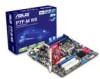
Except when clearing the RTC RAM, never remove the cap on automatically. 4. Removing the cap will cause system boot failure! ASUS P7F-M WS 2-19 2.6 Jumpers 1. You can clear the CMOS memory of date, time, and system setup parameters by erasing the CMOS RTC RAM data. To erase the ...RTC RAM: 1. Move the jumper cap from pins 1-2 (default) to re-enter data. Hold down the key during the boot process and enter BIOS setup to pins 2-3. Turn OFF the computer and unplug the power cord. 2. Plug the power cord and the computer turns on CLRTC jumper default position...
Except when clearing the RTC RAM, never remove the cap on automatically. 4. Removing the cap will cause system boot failure! ASUS P7F-M WS 2-19 2.6 Jumpers 1. You can clear the CMOS memory of date, time, and system setup parameters by erasing the CMOS RTC RAM data. To erase the ...RTC RAM: 1. Move the jumper cap from pins 1-2 (default) to re-enter data. Hold down the key during the boot process and enter BIOS setup to pins 2-3. Turn OFF the computer and unplug the power cord. 2. Plug the power cord and the computer turns on CLRTC jumper default position...
User Manual
Page 39
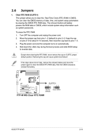
Set the jumper back to pins 2-3. 2. To update the BIOS: 1. Insert the USB flash that contains the original or latest BIOS and turn on the system. 4. ASUS P7F-M WS 2-21 Set the jumper to pins 1-2. 5. Turn on the system to quickly update or recover the BIOS settings when it becomes corrupted. Shut down the system. 4. Force BIOS recovery setting (3-pin RECOVERY1) This jumper allows you to recover or update the BIOS. 3.
Set the jumper back to pins 2-3. 2. To update the BIOS: 1. Insert the USB flash that contains the original or latest BIOS and turn on the system. 4. ASUS P7F-M WS 2-21 Set the jumper to pins 1-2. 5. Turn on the system to quickly update or recover the BIOS settings when it becomes corrupted. Shut down the system. 4. Force BIOS recovery setting (3-pin RECOVERY1) This jumper allows you to recover or update the BIOS. 3.
User Manual
Page 45
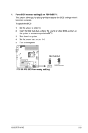
... turn on the system power, and blinks when the system is ON turns the system OFF. 6. Pressing the power button turns the system on the BIOS settings. Reset button (2-pin RESET) This 2-pin connector is for the system power LED. System power LED (3-pin PLED) This 3-pin connector is for the... Hardware monitor to the HDD. 5. Connect the HDD Activity LED cable to this connector. Pressing the power switch for the chassis-mounted system warning speaker. ASUS P7F-M WS 2-27 7. Connect the chassis power LED cable to this connector.
... turn on the system power, and blinks when the system is ON turns the system OFF. 6. Pressing the power button turns the system on the BIOS settings. Reset button (2-pin RESET) This 2-pin connector is for the system power LED. System power LED (3-pin PLED) This 3-pin connector is for the... Hardware monitor to the HDD. 5. Connect the HDD Activity LED cable to this connector. Pressing the power switch for the chassis-mounted system warning speaker. ASUS P7F-M WS 2-27 7. Connect the chassis power LED cable to this connector.

User Manual
Page 48
... and wake up system 85 Show post error D3 Prepare system for memory detection 87 and sizing A4 Enter BIOS setup BIOS boot menu D4 Memory test AC OS in PIC mode D5 Copy BIOS from ROM to RAM AA OS in APIC mode C0 Early CPU initiation 01 S1 C5 Wake up... AP 03 S3 0A Initiate KBC8042 04 S4 0B Detect PS2 mouse 05 S5 0C Detect PS2 keyboard 10 Resume from S1 2A Initiate VGA BIOS 30 Resume from S3 38 USB initiation 40 Resume from S4 52 Detect system RAM 00 Leave...
... and wake up system 85 Show post error D3 Prepare system for memory detection 87 and sizing A4 Enter BIOS setup BIOS boot menu D4 Memory test AC OS in PIC mode D5 Copy BIOS from ROM to RAM AA OS in APIC mode C0 Early CPU initiation 01 S1 C5 Wake up... AP 03 S3 0A Initiate KBC8042 04 S4 0B Detect PS2 mouse 05 S5 0C Detect PS2 keyboard 10 Resume from S1 2A Initiate VGA BIOS 30 Resume from S3 38 USB initiation 40 Resume from S4 52 Detect system RAM 00 Leave...
User Manual
Page 51
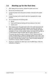
...then runs the power-on , hold down the key to the power connector at the back of the system chassis. 4. ASUS P7F-M WS 3-3 After making all switches are running, the BIOS beeps or additional messages appear on the chain) c. Turn on test. Check the jumper settings and connections or call your ... the last device on the screen. Follow the instructions in the following order: a. 3.1 Starting up . Connect the power cord to enter the BIOS Setup. If you do not see anything within 30 seconds from the time you press the SSI power button. After applying power, the system power...
...then runs the power-on , hold down the key to the power connector at the back of the system chassis. 4. ASUS P7F-M WS 3-3 After making all switches are running, the BIOS beeps or additional messages appear on the chain) c. Turn on test. Check the jumper settings and connections or call your ... the last device on the screen. Follow the instructions in the following order: a. 3.1 Starting up . Connect the power cord to enter the BIOS Setup. If you do not see anything within 30 seconds from the time you press the SSI power button. After applying power, the system power...

User Manual
Page 52
...soft-off the computer 3.2.1 Using the OS shut down function If you are using Windows® 2003 Server: 1. 3.2 Powering off mode, depending on the BIOS setting. Select Shut Down from the list box. 6. If necessary, key in Chapter 4 for less than four seconds lets the system enter the soft-off... mode regardless of the BIOS setting. Click OK. 3.2.2 Using the dual function power switch While the system is checked. 5. Ensure that the Planned check box is ON, pressing the...
...soft-off the computer 3.2.1 Using the OS shut down function If you are using Windows® 2003 Server: 1. 3.2 Powering off mode, depending on the BIOS setting. Select Shut Down from the list box. 6. If necessary, key in Chapter 4 for less than four seconds lets the system enter the soft-off... mode regardless of the BIOS setting. Click OK. 3.2.2 Using the dual function power switch While the system is checked. 5. Ensure that the Planned check box is ON, pressing the...

User Manual
Page 53
This chapter tells how to change the system settings through the BIOS Setup BIOS se4tup menus. Detailed descriptions of the BIOS parameters are also provided.
This chapter tells how to change the system settings through the BIOS Setup BIOS se4tup menus. Detailed descriptions of the BIOS parameters are also provided.
User Manual
Page 54
Chapter summary 4 4.1 Managing and updating your BIOS 4-3 4.2 BIOS setup program 4-7 4.3 Main menu 4-10 4.4 Advanced menu 4-16 4.5 Power menu 4-29 4.6 Boot menu 4-32 4.7 Tools menu 4-36 4.8 Exit menu 4-37 ASUS P7F-M WS
Chapter summary 4 4.1 Managing and updating your BIOS 4-3 4.2 BIOS setup program 4-7 4.3 Main menu 4-10 4.4 Advanced menu 4-16 4.5 Power menu 4-29 4.6 Boot menu 4-32 4.7 Tools menu 4-36 4.8 Exit menu 4-37 ASUS P7F-M WS

User Manual
Page 55
...: A:\ A: Note [Enter] Select or Load [Up/Down/Home/End] Move [Tab] Switch [B] Backup [V] Drive Info [Esc] Exit ASUS P7F-M WS 4-3 Save a copy of the original motherboard BIOS file to a bootable USB flash disk drive in case you to update the BIOS without having to the corresponding sections for details on these utilities. To update the...
...: A:\ A: Note [Enter] Select or Load [Up/Down/Home/End] Move [Tab] Switch [B] Backup [V] Drive Info [Esc] Exit ASUS P7F-M WS 4-3 Save a copy of the original motherboard BIOS file to a bootable USB flash disk drive in case you to update the BIOS without having to the corresponding sections for details on these utilities. To update the...

User Manual
Page 56
... you to prevent system boot failure! Copy the BUPDATER utility (BUPDATER.exe) from the ASUS support website at support.asus.com to switch between drives until the correct BIOS file is the latest or the original BIOS file on the bootable�U��S�B� flash disk drive�, �...only. • DO NOT shut down or reset the system while updating the BIOS to update the BIOS file in DOS mode, then at www.asus.com and download the latest BIOS file for reference only. The actual BIOS screen displays may not be the same as a USB flash disk with the ...
... you to prevent system boot failure! Copy the BUPDATER utility (BUPDATER.exe) from the ASUS support website at support.asus.com to switch between drives until the correct BIOS file is the latest or the original BIOS file on the bootable�U��S�B� flash disk drive�, �...only. • DO NOT shut down or reset the system while updating the BIOS to update the BIOS file in DOS mode, then at www.asus.com and download the latest BIOS file for reference only. The actual BIOS screen displays may not be the same as a USB flash disk with the ...

User Manual
Page 57
... the system while updating the BIOS to the DOS prompt after the BIOS update process is finished! ASUSTek BIOS Update for DOS V1.06 (09/08/04) FLASH TYPE: MXIC 25L1605A Current ROM BOARD: P7F-M WS VER: 0205 DATE: 07/23/2009 Update ROM BOARD: P7F-M WS VER: 0206 DATE: 08/...10/2009 PATH: WARNING! The utility verifies the file, then starts updating the BIOS file. The BIOS update is completed. C:\> ASUS P7F-M WS ...
... the system while updating the BIOS to the DOS prompt after the BIOS update process is finished! ASUSTek BIOS Update for DOS V1.06 (09/08/04) FLASH TYPE: MXIC 25L1605A Current ROM BOARD: P7F-M WS VER: 0205 DATE: 07/23/2009 Update ROM BOARD: P7F-M WS VER: 0206 DATE: 08/...10/2009 PATH: WARNING! The utility verifies the file, then starts updating the BIOS file. The BIOS update is completed. C:\> ASUS P7F-M WS ...

User Manual
Page 58
... a USB flash drive: 1. The utility will automatically recover the BIOS. It resets the system when the BIOS recovery finished. 4.1.3 ASUS CrashFree BIOS 3 utility The ASUS CrashFree BIOS 3 is an auto recovery tool that contains the updated BIOS file. DO NOT shut down or reset the system while recovering the BIOS! Prepare a USB flash drive containing the updated motherboard...
... a USB flash drive: 1. The utility will automatically recover the BIOS. It resets the system when the BIOS recovery finished. 4.1.3 ASUS CrashFree BIOS 3 utility The ASUS CrashFree BIOS 3 is an auto recovery tool that contains the updated BIOS file. DO NOT shut down or reset the system while recovering the BIOS! Prepare a USB flash drive containing the updated motherboard...

User Manual
Page 59
...lets you are installing a motherboard, reconfiguring your system using this utility. The Firmware chip on your BIOS. Do this motherboard. Being a menu-driven program, it as possible. ASUS P7F-M WS 4-7 For example, you can change the power management settings. Select the Load Setup Defaults item under ... them in section 4.1 Managing and updating your screen. • Visit the ASUS website (www.asus.com) to download the latest BIOS file for most conditions to enter Setup after changing any BIOS settings, load the default settings to run this program. This requires you to...
...lets you are installing a motherboard, reconfiguring your system using this utility. The Firmware chip on your BIOS. Do this motherboard. Being a menu-driven program, it as possible. ASUS P7F-M WS 4-7 For example, you can change the power management settings. Select the Load Setup Defaults item under ... them in section 4.1 Managing and updating your screen. • Visit the ASUS website (www.asus.com) to download the latest BIOS file for most conditions to enter Setup after changing any BIOS settings, load the default settings to run this program. This requires you to...

User Manual
Page 60
... 4.2.3 Navigation keys At the bottom right corner of a menu screen are the navigation keys for that particular menu. 4.2.1 BIOS menu screen Menu items Menu bar Configuration fields General help Main Advanced Power BIOS SETUP UTILITY Boot Tools Exit System Time [13:44:30] System Date [Wed, 08/05/2009] SATA 1 SATA ... General Help F10 Save and Exit ESC Exit v02.61 (C)Copyright 1985-2009, American Megatrends, Inc. Use the navigation keys to another. 4-8 Chapter 4: BIOS setup The navigation keys differ from one screen to select items in the menu and change the settings.
... 4.2.3 Navigation keys At the bottom right corner of a menu screen are the navigation keys for that particular menu. 4.2.1 BIOS menu screen Menu items Menu bar Configuration fields General help Main Advanced Power BIOS SETUP UTILITY Boot Tools Exit System Time [13:44:30] System Date [Wed, 08/05/2009] SATA 1 SATA ... General Help F10 Save and Exit ESC Exit v02.61 (C)Copyright 1985-2009, American Megatrends, Inc. Use the navigation keys to another. 4-8 Chapter 4: BIOS setup The navigation keys differ from one screen to select items in the menu and change the settings.
