
User Manual
Page 15
... of the above items is damaged or missing, contact your motherboard package for buying an ASUS® P7F-M WS motherboard! Before you for the following items. Standard Gift Box Pack P7F-M WS Cables SATA data cable 6 Accessories IO shield 1 Card ASUS MIO audio card 1 Application CD Support CD 1 Documentation User Guide 1 Packing Qty. 1 pcs per carton...
... of the above items is damaged or missing, contact your motherboard package for buying an ASUS® P7F-M WS motherboard! Before you for the following items. Standard Gift Box Pack P7F-M WS Cables SATA data cable 6 Accessories IO shield 1 Card ASUS MIO audio card 1 Application CD Support CD 1 Documentation User Guide 1 Packing Qty. 1 pcs per carton...

User Manual
Page 17
DDR3 memory support The P7F-M WS supports UDIMM and RDIMM DDR3 memory that features data transfer rates of 1333/1066 MHZ to meet the higher bandwidth requirements of DDR3 which provide a ... supports the latest PCIe 2.0 device for the memory is backward compatible with dual Gigabit LAN controllers and ports which makes it an ideal memory solution. ASUS P7F-M WS 1-5 The 2-channel DDR3 architecture boosts system performance, eliminating bottlenecks. The onboard Intel 82574L Gigabit LAN controllers use the PCI Express interface and could achieve network...
DDR3 memory support The P7F-M WS supports UDIMM and RDIMM DDR3 memory that features data transfer rates of 1333/1066 MHZ to meet the higher bandwidth requirements of DDR3 which provide a ... supports the latest PCIe 2.0 device for the memory is backward compatible with dual Gigabit LAN controllers and ports which makes it an ideal memory solution. ASUS P7F-M WS 1-5 The 2-channel DDR3 architecture boosts system performance, eliminating bottlenecks. The onboard Intel 82574L Gigabit LAN controllers use the PCI Express interface and could achieve network...

User Manual
Page 20
Diagnosis card installation (optional 2-29 ASUS P7F-M WS Chapter summary 2 2.1 Before you proceed 2-3 2.2 Motherboard overview 2-4 2.3 Central Processing Unit (CPU 2-8 2.4 System memory 2-13 2.5 Expansion slots 2-15 2.6 Jumpers 2-19 2.7 Connectors 2-22 2.8 G.P.
Diagnosis card installation (optional 2-29 ASUS P7F-M WS Chapter summary 2 2.1 Before you proceed 2-3 2.2 Motherboard overview 2-4 2.3 Central Processing Unit (CPU 2-8 2.4 System memory 2-13 2.5 Expansion slots 2-15 2.6 Jumpers 2-19 2.7 Connectors 2-22 2.8 G.P.
User Manual
Page 21
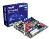
..., place it on a grounded antistatic pad or in the bag that came with a standby power LED. 2.1 Before you proceed Take note of the onboard LED ASUS P7F-M WS 2-3 Failure to do so may cause severe damage to the motherboard, peripherals, and/or components.
..., place it on a grounded antistatic pad or in the bag that came with a standby power LED. 2.1 Before you proceed Take note of the onboard LED ASUS P7F-M WS 2-3 Failure to do so may cause severe damage to the motherboard, peripherals, and/or components.

User Manual
Page 23
2.2.3 Motherboard layout ASUS P7F-M WS 2-5
2.2.3 Motherboard layout ASUS P7F-M WS 2-5
User Manual
Page 27
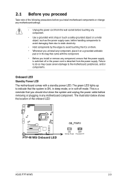
Gold triangle mark Alignment keys CPU notches ASUS P7F-M WS 2-9 The CPU fits in the direction of the arrow until the load plate is on the bottom‑left corner of the socket, and then fit the socket alignment keys into the socket to prevent bending the connectors on the socket and damaging the CPU! PnP cap 5. DO NOT force the CPU into the CPU notches. Position the CPU over the socket, ensuring that the gold triangle is completely lifted. Remove the PnP cap from the CPU socket. Lift the load lever in only one correct orientation. Load plate 4. 3.
Gold triangle mark Alignment keys CPU notches ASUS P7F-M WS 2-9 The CPU fits in the direction of the arrow until the load plate is on the bottom‑left corner of the socket, and then fit the socket alignment keys into the socket to prevent bending the connectors on the socket and damaging the CPU! PnP cap 5. DO NOT force the CPU into the CPU notches. Position the CPU over the socket, ensuring that the gold triangle is completely lifted. Remove the PnP cap from the CPU socket. Lift the load lever in only one correct orientation. Load plate 4. 3.

User Manual
Page 29
... the CPU heatsink and fan: 1. Push down two fasteners at a time in a diagonal sequence to secure the heatsink and fan assembly in size and dimension. B 2. ASUS P7F-M WS 2-11 A B A A B 1 B A 1 Orient the heatsink and fan assembly such that the Thermal Interface Material is incompatible with the LGA775 and LGA1366 sockets in place. Place the...
... the CPU heatsink and fan: 1. Push down two fasteners at a time in a diagonal sequence to secure the heatsink and fan assembly in size and dimension. B 2. ASUS P7F-M WS 2-11 A B A A B 1 B A 1 Orient the heatsink and fan assembly such that the Thermal Interface Material is incompatible with the LGA775 and LGA1366 sockets in place. Place the...

User Manual
Page 31
..., or 1 GB, 2 GB, 4 GB Unbuffered with the same CAS latency. 2.4 System memory 2.4.1 Overview The motherboard comes with less power consumption. DDR3 modules are not supported ASUS P7F-M WS 2-13 A DDR3 module has the same physical dimensions as a DDR2 DIMM but is recommended that you obtain memory modules from 1066 or 1333 MHz DIMM...
..., or 1 GB, 2 GB, 4 GB Unbuffered with the same CAS latency. 2.4 System memory 2.4.1 Overview The motherboard comes with less power consumption. DDR3 modules are not supported ASUS P7F-M WS 2-13 A DDR3 module has the same physical dimensions as a DDR2 DIMM but is recommended that you obtain memory modules from 1066 or 1333 MHz DIMM...

User Manual
Page 33
... the future, you may cause you physical injury and damage motherboard components. 2.5.1 Installing an expansion card To install an expansion card: 1. Refer to the card. ASUS P7F-M WS 2-15
... the future, you may cause you physical injury and damage motherboard components. 2.5.1 Installing an expansion card To install an expansion card: 1. Refer to the card. ASUS P7F-M WS 2-15
User Manual
Page 35
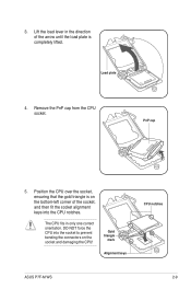
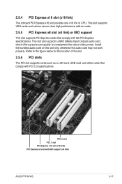
... card on cards. 2.5.5 PCI Express x8 slot (x4 link) or MIO support This slot supports PCI Express cards that comply with MIO support (x4 link) ASUS P7F-M WS 2-17 This slot supports VGA cards and various server class high performance add-on this slot only, otherwise the audio card may not work properly...
... card on cards. 2.5.5 PCI Express x8 slot (x4 link) or MIO support This slot supports PCI Express cards that comply with MIO support (x4 link) ASUS P7F-M WS 2-17 This slot supports VGA cards and various server class high performance add-on this slot only, otherwise the audio card may not work properly...
User Manual
Page 37
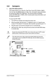
... Clock (RTC) RAM in CMOS, which include system setup information such as system passwords. The onboard button cell battery powers the RAM data in CMOS. ASUS P7F-M WS 2-19 Clear RTC RAM (CLRTC1) This jumper allows you to re-enter data. To erase the RTC RAM: 1. Plug the power cord and the computer...
... Clock (RTC) RAM in CMOS, which include system setup information such as system passwords. The onboard button cell battery powers the RAM data in CMOS. ASUS P7F-M WS 2-19 Clear RTC RAM (CLRTC1) This jumper allows you to re-enter data. To erase the RTC RAM: 1. Plug the power cord and the computer...
User Manual
Page 39
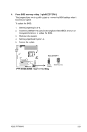
Shut down the system. 4. Set the jumper back to recover or update the BIOS. 3. Turn on the system to pins 1-2. 5. Insert the USB flash that contains the original or latest BIOS and turn on the system. ASUS P7F-M WS 2-21 Force BIOS recovery setting (3-pin RECOVERY1) This jumper allows you to pins 2-3. 2. To update the BIOS: 1. 4. Set the jumper to quickly update or recover the BIOS settings when it becomes corrupted.
Shut down the system. 4. Set the jumper back to recover or update the BIOS. 3. Turn on the system to pins 1-2. 5. Insert the USB flash that contains the original or latest BIOS and turn on the system. ASUS P7F-M WS 2-21 Force BIOS recovery setting (3-pin RECOVERY1) This jumper allows you to pins 2-3. 2. To update the BIOS: 1. 4. Set the jumper to quickly update or recover the BIOS settings when it becomes corrupted.
User Manual
Page 41
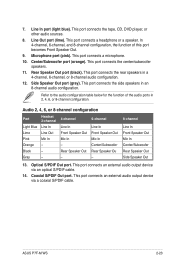
... Line In Line In Lime Line Out Front Speaker Out Front Speaker Out Pink Mic In Mic In Mic In Orange - - Optical S/PDIF Out port. ASUS P7F-M WS 2-23 This port connects the tape, CD, DVD player, or other audio sources. 8. In 4-channel, 6-channel, and 8-channel configuration, the function of the audio ports...
... Line In Line In Lime Line Out Front Speaker Out Front Speaker Out Pink Mic In Mic In Mic In Orange - - Optical S/PDIF Out port. ASUS P7F-M WS 2-23 This port connects the tape, CD, DVD player, or other audio sources. 8. In 4-channel, 6-channel, and 8-channel configuration, the function of the audio ports...
User Manual
Page 43
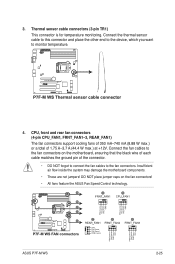
Insufficient air flow inside the system may damage the motherboard components. • These are not jumpers! ASUS P7F-M WS 2-25 CPU, front and rear fan connectors (4-pin CPU_FAN1, FRNT_FAN1-3, REAR_FAN1) The fan connectors support cooling fans of 350 mA-740 mA (8.88 W max.) or a ... connector and place the other end to the device, which you want to the fan connectors on the fan connectors! • All fans feature the ASUS Fan Speed Control technology. DO NOT place jumper caps on the motherboard, ensuring that the black wire of each cable matches the ground pin of...
Insufficient air flow inside the system may damage the motherboard components. • These are not jumpers! ASUS P7F-M WS 2-25 CPU, front and rear fan connectors (4-pin CPU_FAN1, FRNT_FAN1-3, REAR_FAN1) The fan connectors support cooling fans of 350 mA-740 mA (8.88 W max.) or a ... connector and place the other end to the device, which you want to the fan connectors on the fan connectors! • All fans feature the ASUS Fan Speed Control technology. DO NOT place jumper caps on the motherboard, ensuring that the black wire of each cable matches the ground pin of...
User Manual
Page 45
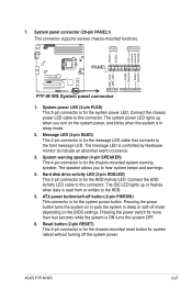
... 2-pin connector is for the chassis-mounted reset button for the system power LED. Connect the HDD Activity LED cable to the front message LED. ASUS P7F-M WS 2-27 Hard disk drive activity LED (2-pin HDDLED) This 2-pin connector is for more than four seconds while the system is for the chassis-mounted...
... 2-pin connector is for the chassis-mounted reset button for the system power LED. Connect the HDD Activity LED cable to the front message LED. ASUS P7F-M WS 2-27 Hard disk drive activity LED (2-pin HDDLED) This 2-pin connector is for more than four seconds while the system is for the chassis-mounted...

User Manual
Page 47
... sits on the motherboard. 2. Locate the TPM connector (20-1 pin TPM) on the connector completely. Diagnosis card Ensure to turn ON or OFF the computer. ASUS P7F-M WS 2-29 With the LEDs of the diagnosis card facing to avoid electrical shock hazard. 1. Reset Button.
... sits on the motherboard. 2. Locate the TPM connector (20-1 pin TPM) on the connector completely. Diagnosis card Ensure to turn ON or OFF the computer. ASUS P7F-M WS 2-29 With the LEDs of the diagnosis card facing to avoid electrical shock hazard. 1. Reset Button.

User Manual
Page 50
Chapter summary 3 3.1 Starting up for the first time 3-3 3.2 Turning off the computer 3-4 ASUS P7F-M WS
Chapter summary 3 3.1 Starting up for the first time 3-3 3.2 Turning off the computer 3-4 ASUS P7F-M WS
User Manual
Page 51
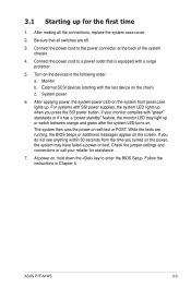
... b. If your retailer for the first time 1. If you do not see anything within 30 seconds from the time you press the SSI power button. ASUS P7F-M WS 3-3 Turn on self-test or POST. Check the jumper settings and connections or call your monitor complies with the last device on the screen. Follow...
... b. If your retailer for the first time 1. If you do not see anything within 30 seconds from the time you press the SSI power button. ASUS P7F-M WS 3-3 Turn on self-test or POST. Check the jumper settings and connections or call your monitor complies with the last device on the screen. Follow...
User Manual
Page 54
Chapter summary 4 4.1 Managing and updating your BIOS 4-3 4.2 BIOS setup program 4-7 4.3 Main menu 4-10 4.4 Advanced menu 4-16 4.5 Power menu 4-29 4.6 Boot menu 4-32 4.7 Tools menu 4-36 4.8 Exit menu 4-37 ASUS P7F-M WS
Chapter summary 4 4.1 Managing and updating your BIOS 4-3 4.2 BIOS setup program 4-7 4.3 Main menu 4-10 4.4 Advanced menu 4-16 4.5 Power menu 4-29 4.6 Boot menu 4-32 4.7 Tools menu 4-36 4.8 Exit menu 4-37 ASUS P7F-M WS

User Manual
Page 55
... ROM BOARD: Unknown VER: Unknown DATE: Unknown PATH: A:\ A: Note [Enter] Select or Load [Up/Down/Home/End] Move [Tab] Switch [B] Backup [V] Drive Info [Esc] Exit ASUS P7F-M WS 4-3 BUPDATER utility (Updates the BIOS in case you start using a bootable USB flash disk drive when the BIOS file fails or gets corrupted.) Refer to...
... ROM BOARD: Unknown VER: Unknown DATE: Unknown PATH: A:\ A: Note [Enter] Select or Load [Up/Down/Home/End] Move [Tab] Switch [B] Backup [V] Drive Info [Esc] Exit ASUS P7F-M WS 4-3 BUPDATER utility (Updates the BIOS in case you start using a bootable USB flash disk drive when the BIOS file fails or gets corrupted.) Refer to...


