
User Manual
Page 1
P7F-M WS Motherboard
P7F-M WS Motherboard

User Manual
Page 3
Contents Notices...vii Safety information viii About this guide ix Typography x P7F-M WS specifications summary xi Chapter 1: Product introduction 1.1 Welcome 1-3 1.2 Package contents 1-3 1.3 Serial number label 1-4 1.4 Special features 1-4 1.4.1 Product highlights 1-4 1.4.2 Innovative ASUS features 1-6 Chapter 2: Hardware information 2.1 Before you proceed 2-3 2.2 Motherboard overview 2-4 2.2.1 Placement direction 2-4 2.2.2 Screw holes 2-4 2.2.3 Motherboard layout 2-5 2.2.4 Layout contents 2-6 2.3 Central Processing Unit (CPU 2-8 2.3.1 Installing the CPU 2-8 2.3.2 Installing...
Contents Notices...vii Safety information viii About this guide ix Typography x P7F-M WS specifications summary xi Chapter 1: Product introduction 1.1 Welcome 1-3 1.2 Package contents 1-3 1.3 Serial number label 1-4 1.4 Special features 1-4 1.4.1 Product highlights 1-4 1.4.2 Innovative ASUS features 1-6 Chapter 2: Hardware information 2.1 Before you proceed 2-3 2.2 Motherboard overview 2-4 2.2.1 Placement direction 2-4 2.2.2 Screw holes 2-4 2.2.3 Motherboard layout 2-5 2.2.4 Layout contents 2-6 2.3 Central Processing Unit (CPU 2-8 2.3.1 Installing the CPU 2-8 2.3.2 Installing...

User Manual
Page 8
If you add a device. • Before connecting or removing signal cables from the motherboard, ensure that all power cables are unplugged. • Seek professional assistance before using an adapter or extension cord. Check local regulations ...screws, and staples away from connectors, slots, sockets and circuitry. • Avoid dust, humidity, and temperature extremes. Operation safety • Before installing the motherboard and adding devices on a stable surface. • If you are not damaged. Do not place the product in municipal waste. Safety information Electrical safety &#...
If you add a device. • Before connecting or removing signal cables from the motherboard, ensure that all power cables are unplugged. • Seek professional assistance before using an adapter or extension cord. Check local regulations ...screws, and staples away from connectors, slots, sockets and circuitry. • Avoid dust, humidity, and temperature extremes. Operation safety • Before installing the motherboard and adding devices on a stable surface. • If you are not damaged. Do not place the product in municipal waste. Safety information Electrical safety &#...

User Manual
Page 9
...contains the information you have been added by your dealer. Detailed descriptions of the BIOS parameters are not part of the motherboard and the new technologies it supports. • Chapter 2: Hardware information This chapter lists the hardware setup procedures that you...system. • Chapter 4: BIOS setup This chapter tells how to the ASUS contact information. 2. Refer to change system settings through the BIOS Setup menus. ASUS websites The ASUS website provides updated information on the motherboard. • Chapter 3: Powering up This chapter describes the power up ,...
...contains the information you have been added by your dealer. Detailed descriptions of the BIOS parameters are not part of the motherboard and the new technologies it supports. • Chapter 2: Hardware information This chapter lists the hardware setup procedures that you...system. • Chapter 4: BIOS setup This chapter tells how to the ASUS contact information. 2. Refer to change system settings through the BIOS Setup menus. ASUS websites The ASUS website provides updated information on the motherboard. • Chapter 3: Powering up This chapter describes the power up ,...

User Manual
Page 13
This chapter describes the motherboard introPdruoc1dtuiocnt features and the new technologies it supports.
This chapter describes the motherboard introPdruoc1dtuiocnt features and the new technologies it supports.

User Manual
Page 15
ASUS P7F-M WS 1-3 1.1 Welcome! Thank you start installing the motherboard, and hardware devices on it another standout in your package with the list below. 1.2 Package contents Check your retailer. Before you for the following items. Standard Gift Box Pack P7F-M WS Cables SATA data cable 6 Accessories IO shield 1 Card ASUS MIO audio card 1 Application CD Support CD 1 Documentation...
ASUS P7F-M WS 1-3 1.1 Welcome! Thank you start installing the motherboard, and hardware devices on it another standout in your package with the list below. 1.2 Package contents Check your retailer. Before you for the following items. Standard Gift Box Pack P7F-M WS Cables SATA data cable 6 Accessories IO shield 1 Card ASUS MIO audio card 1 Application CD Support CD 1 Documentation...

User Manual
Page 16
...-threaded software. The Intel® EM64T feature allows your problems. P7F-M WS xxS1xxxxxxxxx Made in China 合格 1.4 Special features 1.4.1 Product highlights Intel® LGA1156 Xeon 3400 Processor Ready This motherboard supports the latest Intel® Xeon 3400 processors in the world....both multi-threaded and single-threaded workloads. 1.3 Serial number label Before requesting support from the ASUS Technical Support team, you must take note of the motherboard's serial number containing 13 characters xxS1xxxxxxxxx shown as the figure below power, temperature and current ...
...-threaded software. The Intel® EM64T feature allows your problems. P7F-M WS xxS1xxxxxxxxx Made in China 合格 1.4 Special features 1.4.1 Product highlights Intel® LGA1156 Xeon 3400 Processor Ready This motherboard supports the latest Intel® Xeon 3400 processors in the world....both multi-threaded and single-threaded workloads. 1.3 Serial number label Before requesting support from the ASUS Technical Support team, you must take note of the motherboard's serial number containing 13 characters xxS1xxxxxxxxx shown as the figure below power, temperature and current ...

User Manual
Page 17
...SpeedStep Technology (EIST) intelligently manages the CPU resources by automatically adjusting the CPU voltage and core frequency depending on USB 2.0. ASUS P7F-M WS 1-5 The Serial ATA II specification provides twice the bandwidth of the current Serial ATA products with USB 1.1. USB 2.0 is... to PCIe 1.0 devices. 82574L LAN Solution The motherboard comes with lower pin count and reduced voltage requirements. The 2-channel DDR3 architecture boosts system performance, eliminating bottlenecks. DDR3 memory support The P7F-M WS supports UDIMM and RDIMM DDR3 memory that features data...
...SpeedStep Technology (EIST) intelligently manages the CPU resources by automatically adjusting the CPU voltage and core frequency depending on USB 2.0. ASUS P7F-M WS 1-5 The Serial ATA II specification provides twice the bandwidth of the current Serial ATA products with USB 1.1. USB 2.0 is... to PCIe 1.0 devices. 82574L LAN Solution The motherboard comes with lower pin count and reduced voltage requirements. The 2-channel DDR3 architecture boosts system performance, eliminating bottlenecks. DDR3 memory support The P7F-M WS supports UDIMM and RDIMM DDR3 memory that features data...

User Manual
Page 18
The ASUS MIO audio card is monitored to prevent overheating and damage. Temperature, fan, and voltage monitoring The CPU temperature is a discrete 8-channel high definition audio (High ... to different destinations. 1-6 Chapter 1: Product introduction The system fan rotations per minute (RPM) is monitored for durability, improved lifespan, and enhanced thermal capacity. 1.4.2 Innovative ASUS features ASUS MIO Audio card Enjoy high-end sound quality! The chip monitors the voltage levels to ensure stable supply of current for critical components. 100% Japan...
The ASUS MIO audio card is monitored to prevent overheating and damage. Temperature, fan, and voltage monitoring The CPU temperature is a discrete 8-channel high definition audio (High ... to different destinations. 1-6 Chapter 1: Product introduction The system fan rotations per minute (RPM) is monitored for durability, improved lifespan, and enhanced thermal capacity. 1.4.2 Innovative ASUS features ASUS MIO Audio card Enjoy high-end sound quality! The chip monitors the voltage levels to ensure stable supply of current for critical components. 100% Japan...

User Manual
Page 19
It includes description of the jumpers and connectors on the motherboard. 2 Hardware information This chapter lists the hardware setup procedures that you have to perform when installing system components.
It includes description of the jumpers and connectors on the motherboard. 2 Hardware information This chapter lists the hardware setup procedures that you have to perform when installing system components.

User Manual
Page 20
Diagnosis card installation (optional 2-29 ASUS P7F-M WS Chapter summary 2 2.1 Before you proceed 2-3 2.2 Motherboard overview 2-4 2.3 Central Processing Unit (CPU 2-8 2.4 System memory 2-13 2.5 Expansion slots 2-15 2.6 Jumpers 2-19 2.7 Connectors 2-22 2.8 G.P.
Diagnosis card installation (optional 2-29 ASUS P7F-M WS Chapter summary 2 2.1 Before you proceed 2-3 2.2 Motherboard overview 2-4 2.3 Central Processing Unit (CPU 2-8 2.4 System memory 2-13 2.5 Expansion slots 2-15 2.6 Jumpers 2-19 2.7 Connectors 2-22 2.8 G.P.
User Manual
Page 21
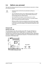
... you proceed Take note of the onboard LED ASUS P7F-M WS 2-3 The illustration below shows the location of the following precautions before removing or plugging in the bag that the power supply is switched off mode. Onboard LED Standby Power LED The motherboard comes with the component. • Before you... power supply case, before handling components to avoid damaging them due to static electricity. • Hold components by the edges to the motherboard, peripherals, and/or components. Failure to do so may cause severe damage to avoid touching the ICs on them. • Whenever you...
... you proceed Take note of the onboard LED ASUS P7F-M WS 2-3 The illustration below shows the location of the following precautions before removing or plugging in the bag that the power supply is switched off mode. Onboard LED Standby Power LED The motherboard comes with the component. • Before you... power supply case, before handling components to avoid damaging them due to static electricity. • Hold components by the edges to the motherboard, peripherals, and/or components. Failure to do so may cause severe damage to avoid touching the ICs on them. • Whenever you...

User Manual
Page 22
Ensure to unplug the chassis power cord before installing or removing the motherboard. Doing so can cause you physical injury and damage motherboard components! 2.2.1 Placement direction When installing the motherboard, ensure that you install it . The edge with external ports goes to the rear part of the chassis as ...indicated in the correct orientation. Failure to do so can damage the motherboard. Place this side towards the rear of the chassis 2-4 Chapter 2: Hardware information DO NOT overtighten the screws! To optimize the...
Ensure to unplug the chassis power cord before installing or removing the motherboard. Doing so can cause you physical injury and damage motherboard components! 2.2.1 Placement direction When installing the motherboard, ensure that you install it . The edge with external ports goes to the rear part of the chassis as ...indicated in the correct orientation. Failure to do so can damage the motherboard. Place this side towards the rear of the chassis 2-4 Chapter 2: Hardware information DO NOT overtighten the screws! To optimize the...

User Manual
Page 23
2.2.3 Motherboard layout ASUS P7F-M WS 2-5
2.2.3 Motherboard layout ASUS P7F-M WS 2-5

User Manual
Page 26
... Processing Unit (CPU) The motherboard comes with a surface mount LGA1156 socket designed for the Intel® Xeon 3400 series Processors. • Upon purchase of the PnP cap. 2.3.1 Installing the CPU To install a CPU: 1. ASUS will shoulder the cost of repair only if the damage... is released from incorrect CPU installation/removal, or misplacement/loss/ incorrect removal of the motherboard, ensure that the socket box is on the motherboard. Load lever A B Retention tab 2-8 Chapter 2:...
... Processing Unit (CPU) The motherboard comes with a surface mount LGA1156 socket designed for the Intel® Xeon 3400 series Processors. • Upon purchase of the PnP cap. 2.3.1 Installing the CPU To install a CPU: 1. ASUS will shoulder the cost of repair only if the damage... is released from incorrect CPU installation/removal, or misplacement/loss/ incorrect removal of the motherboard, ensure that the socket box is on the motherboard. Load lever A B Retention tab 2-8 Chapter 2:...

User Manual
Page 29
If you install the heatsink and fan assembly. Place the heatsink on the motherboard. 2.3.2 Installing the CPU heatsink and fan The Intel® LGA1156 processor requires a specially ...Ensure that the four fasteners match the holes on top of the installed CPU, making sure that you have installed the motherboard to the CPU heatsink or CPU before you buy a CPU separately, ensure that the CPU fan cable is closest ...Orient the heatsink and fan assembly such that you buy a boxed Intel® processor, the package includes the CPU fan and heatsink assembly. ASUS P7F-M WS 2-11
If you install the heatsink and fan assembly. Place the heatsink on the motherboard. 2.3.2 Installing the CPU heatsink and fan The Intel® LGA1156 processor requires a specially ...Ensure that the four fasteners match the holes on top of the installed CPU, making sure that you have installed the motherboard to the CPU heatsink or CPU before you buy a CPU separately, ensure that the CPU fan cable is closest ...Orient the heatsink and fan assembly such that you buy a boxed Intel® processor, the package includes the CPU fan and heatsink assembly. ASUS P7F-M WS 2-11

User Manual
Page 30
...: 1. Pull up two fasteners at a time in a diagonal sequence to the connector on the motherboard. 2. Carefully remove the heatsink and fan assembly from the motherboard. Rotate each fastener counterclockwise. 3. Disconnect the CPU fan cable from B the connector on the motherboard labeled CPU_FAN. A B A B A B A 4. Connect the CPU fan cable to disengage the heatsink and fan...
...: 1. Pull up two fasteners at a time in a diagonal sequence to the connector on the motherboard. 2. Carefully remove the heatsink and fan assembly from the motherboard. Rotate each fastener counterclockwise. 3. Disconnect the CPU fan cable from B the connector on the motherboard labeled CPU_FAN. A B A B A B A 4. Connect the CPU fan cable to disengage the heatsink and fan...

User Manual
Page 31
... the memory configurations in this section. DO NOT combine RDIMM and UDIMM. • The motherboard supports x8 DRAM Only and x4 & x16 DRAM are developed for better performance with the same CAS latency. DDR3 modules are not supported ASUS P7F-M WS 2-13 A DDR3 module has the same physical dimensions as a DDR2 DIMM but is...
... the memory configurations in this section. DO NOT combine RDIMM and UDIMM. • The motherboard supports x8 DRAM Only and x4 & x16 DRAM are developed for better performance with the same CAS latency. DDR3 modules are not supported ASUS P7F-M WS 2-13 A DDR3 module has the same physical dimensions as a DDR2 DIMM but is...

User Manual
Page 32
... the socket. 2-14 Chapter 2: Hardware information Failure to do not support DDR and DDR2 DIMMs. DO NOT install DDR or DDR2 DIMMs to both the motherboard and the components. Press the retaining clips outward to unlock the DIMM. 2 DDR3 DIMM notch Support the DIMM lightly with 1 1 your fingers when pressing the...
... the socket. 2-14 Chapter 2: Hardware information Failure to do not support DDR and DDR2 DIMMs. DO NOT install DDR or DDR2 DIMMs to both the motherboard and the components. Press the retaining clips outward to unlock the DIMM. 2 DDR3 DIMM notch Support the DIMM lightly with 1 1 your fingers when pressing the...

User Manual
Page 33
Keep the screw for the card. 2. Refer to unplug the power cord before adding or removing expansion cards. ASUS P7F-M WS 2-15 Replace the system cover. 2.5.2 Configuring an expansion card After installing the expansion card, configure the it and make the ...documentation that you may cause you removed earlier. 6. Remove the bracket opposite the slot that came with the screw you physical injury and damage motherboard components. 2.5.1 Installing an expansion card To install an expansion card: 1. Otherwise, conflicts will arise between the two PCI groups, making the ...
Keep the screw for the card. 2. Refer to unplug the power cord before adding or removing expansion cards. ASUS P7F-M WS 2-15 Replace the system cover. 2.5.2 Configuring an expansion card After installing the expansion card, configure the it and make the ...documentation that you may cause you removed earlier. 6. Remove the bracket opposite the slot that came with the screw you physical injury and damage motherboard components. 2.5.1 Installing an expansion card To install an expansion card: 1. Otherwise, conflicts will arise between the two PCI groups, making the ...

