
Motherboard Installation Guide
Page 3
...contents 1-2 1.3 Special features 1-2 1.3.1 Product highlights 1-2 1.3.2 Innovative ASUS features 1-4 1.4 Before you proceed 1-6 1.5 Motherboard overview 1-7 1.5.1 Placement direction 1-7 1.5.2 Screw holes 1-7 1.5.3 P5VD2-X Motherboard layout 1-8 1.6 Central Processing Unit (CPU 1-9 1.6.1 Installling the CPU... 1-9 1.6.2 Installling the CPU heatsink and fan 1-12 1.6.3 Uninstalling the CPU heatsink and fan 1-14 1.7 System memory 1-16 1.7.1 Overview 1-16 1.7.2 Memory configurations 1-16...
...contents 1-2 1.3 Special features 1-2 1.3.1 Product highlights 1-2 1.3.2 Innovative ASUS features 1-4 1.4 Before you proceed 1-6 1.5 Motherboard overview 1-7 1.5.1 Placement direction 1-7 1.5.2 Screw holes 1-7 1.5.3 P5VD2-X Motherboard layout 1-8 1.6 Central Processing Unit (CPU 1-9 1.6.1 Installling the CPU... 1-9 1.6.2 Installling the CPU heatsink and fan 1-12 1.6.3 Uninstalling the CPU heatsink and fan 1-14 1.7 System memory 1-16 1.7.1 Overview 1-16 1.7.2 Memory configurations 1-16...

Motherboard Installation Guide
Page 4
... 1-26 1.10.2 Internal connectors 1-28 Chapter 2: BIOS setup 2.1 Managing and updating your BIOS 2-2 2.1.1 ASUS Update utility 2-2 2.1.2 Creating a bootable floppy disk 2-5 2.1.3 ASUS EZ Flash 2 utility 2-6 2.1.4 Updating the BIOS 2-7 2.1.5 Saving the current BIOS file 2-9 2.1.6 ASUS CrashFree BIOS 3 utility 2-10 2.2 BIOS setup program 2-11 2.2.1 BIOS menu screen 2-12 2.2.2 Menu bar... Date 2-15 2.3.3 Legacy Diskette A 2-15 2.3.4 Primary and Secondary IDE Master/Slave 2-16 2.3.5 SATA 1/2 2-18 2.3.6 HDD SMART Monitoring 2-19 2.3.7 Installed Memory 2-19 2.3.8 Usable Memory 2-19 iv
... 1-26 1.10.2 Internal connectors 1-28 Chapter 2: BIOS setup 2.1 Managing and updating your BIOS 2-2 2.1.1 ASUS Update utility 2-2 2.1.2 Creating a bootable floppy disk 2-5 2.1.3 ASUS EZ Flash 2 utility 2-6 2.1.4 Updating the BIOS 2-7 2.1.5 Saving the current BIOS file 2-9 2.1.6 ASUS CrashFree BIOS 3 utility 2-10 2.2 BIOS setup program 2-11 2.2.1 BIOS menu screen 2-12 2.2.2 Menu bar... Date 2-15 2.3.3 Legacy Diskette A 2-15 2.3.4 Primary and Secondary IDE Master/Slave 2-16 2.3.5 SATA 1/2 2-18 2.3.6 HDD SMART Monitoring 2-19 2.3.7 Installed Memory 2-19 2.3.8 Usable Memory 2-19 iv
Motherboard Installation Guide
Page 10
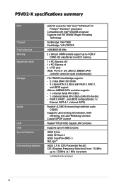
...174; ALC883 6-channel high definition audio CODEC Suppports Jack-sensing, Enumeration, Multi- P5VD2-X specifications summary CPU Chipset Front side bus Memory Expansion slots Storage Audio LAN USB Special features Overclocking features LGA775 socket for Intel® Core™2/Pentium® D/ Pentium®... Coaxial S/PDIF out port Realtek® RTL8110SC Gigabit LAN Controller Supports up to 8 USB 2.0 ports ASUS Q-Fan ASUS EZ Flash 2 ASUS CrashFree BIOS 3 MyLogo™ ASUS C.P.R. (CPU Parameter Recall) SFS (Stepless Frequency Selection) from 133MHz up to 350MHz at 1MHz increment ...
...174; ALC883 6-channel high definition audio CODEC Suppports Jack-sensing, Enumeration, Multi- P5VD2-X specifications summary CPU Chipset Front side bus Memory Expansion slots Storage Audio LAN USB Special features Overclocking features LGA775 socket for Intel® Core™2/Pentium® D/ Pentium®... Coaxial S/PDIF out port Realtek® RTL8110SC Gigabit LAN Controller Supports up to 8 USB 2.0 ports ASUS Q-Fan ASUS EZ Flash 2 ASUS CrashFree BIOS 3 MyLogo™ ASUS C.P.R. (CPU Parameter Recall) SFS (Stepless Frequency Selection) from 133MHz up to 350MHz at 1MHz increment ...

Motherboard Installation Guide
Page 28
...DIMM sockets. • Always install DIMMs with two Double Data Rate 2 (DDR2) Dual Inline Memory Modules (DIMM) sockets. DIMM1 DIMM2 1-16 Chapter 1: Product introduction 1.7 System memory 1.7.1 Overview The motherboard comes with the same CAS latency. A DDR2 module has the same physical dimensions as a ...figure illustrates the location of 128 Mb chips or double sided x16 memory modules. For optimum compatibility, it is recommended that you installed two 2 GB DDR2 memory modules. • This motherboard does not support memory modules made up of the DDR2 DIMM sockets: P5VD2-X ®...
...DIMM sockets. • Always install DIMMs with two Double Data Rate 2 (DDR2) Dual Inline Memory Modules (DIMM) sockets. DIMM1 DIMM2 1-16 Chapter 1: Product introduction 1.7 System memory 1.7.1 Overview The motherboard comes with the same CAS latency. A DDR2 module has the same physical dimensions as a ...figure illustrates the location of 128 Mb chips or double sided x16 memory modules. For optimum compatibility, it is recommended that you installed two 2 GB DDR2 memory modules. • This motherboard does not support memory modules made up of the DDR2 DIMM sockets: P5VD2-X ®...

Motherboard Installation Guide
Page 30
... Patriot Patriot Patriot UMAX Veritech Veritech PM32M16D2B-3.7KC PM64M8D2B-3.7KC PM64M8D2B-3.7KC U2S12D30TP-5C VTD264M8PC6G VTD264M8PC6G - Single-sided DS - Supports one pair of Single-channel memory configuration 1-18 Chapter 1: Product introduction DS GTP01GHLTM56DG DIMM socket support (Optional) A* B* • • • • • • • • • • ... SS PSD2256533 - Supports one module inserted in any slot as one pair of modules inserted into yellow slots as Single-channel memory configuration B - SS 53014051-7100 -
... Patriot Patriot Patriot UMAX Veritech Veritech PM32M16D2B-3.7KC PM64M8D2B-3.7KC PM64M8D2B-3.7KC U2S12D30TP-5C VTD264M8PC6G VTD264M8PC6G - Single-sided DS - Supports one pair of Single-channel memory configuration 1-18 Chapter 1: Product introduction DS GTP01GHLTM56DG DIMM socket support (Optional) A* B* • • • • • • • • • • ... SS PSD2256533 - Supports one module inserted in any slot as one pair of modules inserted into yellow slots as Single-channel memory configuration B - SS 53014051-7100 -
Motherboard Installation Guide
Page 35
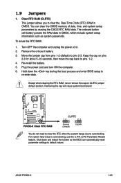
1.9 Jumpers 1. You can automatically reset parameter settings to default values. ASUS P5VD2-X 1-23 Clear RTC RAM (CLRTC) This jumper allows you to pins 1-2. 4. To erase the RTC RAM: 1. Remove the onboard battery. 3. Except when clearing the .... 2. Keep the cap on CLRTC jumper default position. Re-install the battery. 5. Hold down and reboot the system so the BIOS can clear the CMOS memory of date, time, and system setup parameters by erasing the CMOS RTC RAM data.
1.9 Jumpers 1. You can automatically reset parameter settings to default values. ASUS P5VD2-X 1-23 Clear RTC RAM (CLRTC) This jumper allows you to pins 1-2. 4. To erase the RTC RAM: 1. Remove the onboard battery. 3. Except when clearing the .... 2. Keep the cap on CLRTC jumper default position. Re-install the battery. 5. Hold down and reboot the system so the BIOS can clear the CMOS memory of date, time, and system setup parameters by erasing the CMOS RTC RAM data.
Motherboard Installation Guide
Page 56
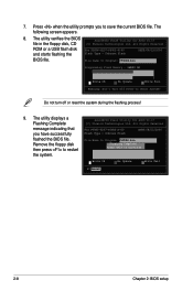
...File Name to Program: P5VD2X.bin Remove the floppy disk then press to restart Flashing Complete Press to Program: P5VD2X.bin Programming Flash Memory - Press when the utility prompts you have successfully Flash Type - Do not turn off or reset the system during the flashing ...process! 9. The utility verifies the BIOS AwardBIOS Flash Utility for ASUS V1.17 (C) Phoenix Technologies Ltd. File Name to Continue the system. All Rights Reserved message indicating that For PT890-8237-P5VD2-X-...
...File Name to Program: P5VD2X.bin Remove the floppy disk then press to restart Flashing Complete Press to Program: P5VD2X.bin Programming Flash Memory - Press when the utility prompts you have successfully Flash Type - Do not turn off or reset the system during the flashing ...process! 9. The utility verifies the BIOS AwardBIOS Flash Utility for ASUS V1.17 (C) Phoenix Technologies Ltd. File Name to Continue the system. All Rights Reserved message indicating that For PT890-8237-P5VD2-X-...

Motherboard Installation Guide
Page 60
...Time System Date Legacy Diskette A: Primary IDE Master Primary IDE Slave Secondary IDE Master Secondary IDE Slave SATA 1 SATA 2 HDD SMART Monitoring Installed Memory Usable Memory 15 : 30 : 36 Mon, Mar 03 2005 [1.44M, 3.5 in this chapter are for special functions For selecting the exit options and loading... press the right or left arrow key on the keyboard until the desired item is highlighted. • The BIOS setup screens shown in .] [ST321122A] [ASUS CDS520/A] [None] [None] [None] [None] [Disabled] 512MB 512MB Select Menu Item Specific Help Change the day, month, year and century. F1:...
...Time System Date Legacy Diskette A: Primary IDE Master Primary IDE Slave Secondary IDE Master Secondary IDE Slave SATA 1 SATA 2 HDD SMART Monitoring Installed Memory Usable Memory 15 : 30 : 36 Mon, Mar 03 2005 [1.44M, 3.5 in this chapter are for special functions For selecting the exit options and loading... press the right or left arrow key on the keyboard until the desired item is highlighted. • The BIOS setup screens shown in .] [ST321122A] [ASUS CDS520/A] [None] [None] [None] [None] [Disabled] 512MB 512MB Select Menu Item Specific Help Change the day, month, year and century. F1:...

Motherboard Installation Guide
Page 63
... Master Primary IDE Slave Secondary IDE Master Secondary IDE Slave SATA 1 SATA 2 HDD SMART Monitoring Installed Memory Usable Memory 15 : 30 : 36 Mon, Mar 03 2005 [1.44M, 3.5 in .] ASUS P5VD2-X 2-15 F1:Help Select Item ESC: Exit Select Menu -/+: Change Value F5: Setup Defaults...A [1.44M, 3.5 in.] Sets the type of the basic system information. Configuration options: [Disabled] [720K , 3.5 in.] [1.44M, 3.5 in .] [ST321122A] [ASUS CDS520/A] [None] [None] [None] [None] [Disabled] 512MB 512MB Select Menu Item Specific Help Change the day, month, year and century. 2.3 Main menu When...
... Master Primary IDE Slave Secondary IDE Master Secondary IDE Slave SATA 1 SATA 2 HDD SMART Monitoring Installed Memory Usable Memory 15 : 30 : 36 Mon, Mar 03 2005 [1.44M, 3.5 in .] ASUS P5VD2-X 2-15 F1:Help Select Item ESC: Exit Select Menu -/+: Change Value F5: Setup Defaults...A [1.44M, 3.5 in.] Sets the type of the basic system information. Configuration options: [Disabled] [720K , 3.5 in.] [1.44M, 3.5 in .] [ST321122A] [ASUS CDS520/A] [None] [None] [None] [None] [Disabled] 512MB 512MB Select Menu Item Specific Help Change the day, month, year and century. 2.3 Main menu When...

Motherboard Installation Guide
Page 67
... disk drive information into BIOS, use a disk utility, such as FDISK, to active. 2.3.6 HDD SMART Monitoring [Disabled] Allows you can write or read /write heads. ASUS P5VD2-X 2-19 Head Shows the number of the hard disk read data from the hard disk. This item is not configurable. Configuration options: [Disabled] [Enabled...
... disk drive information into BIOS, use a disk utility, such as FDISK, to active. 2.3.6 HDD SMART Monitoring [Disabled] Allows you can write or read /write heads. ASUS P5VD2-X 2-19 Head Shows the number of the hard disk read data from the hard disk. This item is not configurable. Configuration options: [Disabled] [Enabled...

Motherboard Installation Guide
Page 71
... item IRQ Resources is set to [Auto], the BIOS automatically configures all the devices in the system. Refer to the section "IRQ Resources" for boot. ASUS P5VD2-X 2-23 Spread Spectrum [+/-0.2%] Configuration options: [Disabled] [+/-0.1%] [+/-0.2%]...[+/-1.0%] Top Performance [Disabled] Configuration options: [Disabled] [Enabled] Primary Display Adapter [PCI-E] Allows you want to assign the IRQ...
... item IRQ Resources is set to [Auto], the BIOS automatically configures all the devices in the system. Refer to the section "IRQ Resources" for boot. ASUS P5VD2-X 2-23 Spread Spectrum [+/-0.2%] Configuration options: [Disabled] [+/-0.1%] [+/-0.2%]...[+/-1.0%] Top Performance [Disabled] Configuration options: [Disabled] [Enabled] Primary Display Adapter [PCI-E] Allows you want to assign the IRQ...

P5SD2-X English Manual E2026
Page 3
Contents Notices vi Safety information vii About this guide viii Typography ix P5SD2-X specifications summary x Chapter 1: Product introduction 1.1 Welcome 1-2 1.2 Package contents 1-2 1.3 Special features 1-2 1.3.1 Product highlights 1-2 1.3.2 Innovative ASUS features 1-4 1.4 Before you proceed 1-5 1.5 Motherboard overview 1-6 1.5.1 Placement direction 1-6 1.5.2 Screw holes 1-6 1.5.3 Motherboard layout 1-7 1.6 Central Processing Unit (CPU 1-8 1.6.1 Installling the CPU 1-8 2.3.2 Installling the CPU heatsink and fan 1-11 2.3.3 Uninstalling the...
Contents Notices vi Safety information vii About this guide viii Typography ix P5SD2-X specifications summary x Chapter 1: Product introduction 1.1 Welcome 1-2 1.2 Package contents 1-2 1.3 Special features 1-2 1.3.1 Product highlights 1-2 1.3.2 Innovative ASUS features 1-4 1.4 Before you proceed 1-5 1.5 Motherboard overview 1-6 1.5.1 Placement direction 1-6 1.5.2 Screw holes 1-6 1.5.3 Motherboard layout 1-7 1.6 Central Processing Unit (CPU 1-8 1.6.1 Installling the CPU 1-8 2.3.2 Installling the CPU heatsink and fan 1-11 2.3.3 Uninstalling the...

P5SD2-X English Manual E2026
Page 10
P5SD2-X specifications summary CPU LGA775 socket for Intel® Pentium® 4/Pentium® D/Intel® Celeron / Celeron D processors Compatible with Intel® PCG 05B/05A and 04B/04A processors Supports Intel® EM64T/EIST Technology Supports Intel® Hyper-Threading Technology Chipset Northbridge: SIS 656 Southbridge: SIS 965L F r o n t S i d e B u s 800/533 MHz Memory... up to 8 USB 2.0 ports Special features AI Overclocking CPU LockFree ASUS Q-Fan ASUS CrashFree BIOS 2 ASUS MyLogo™ ASUS EZ Flash ASUS C.P.R. (CPU Parameter Recall) BIOS features 4 MB Flash ROM, AMI...
P5SD2-X specifications summary CPU LGA775 socket for Intel® Pentium® 4/Pentium® D/Intel® Celeron / Celeron D processors Compatible with Intel® PCG 05B/05A and 04B/04A processors Supports Intel® EM64T/EIST Technology Supports Intel® Hyper-Threading Technology Chipset Northbridge: SIS 656 Southbridge: SIS 965L F r o n t S i d e B u s 800/533 MHz Memory... up to 8 USB 2.0 ports Special features AI Overclocking CPU LockFree ASUS Q-Fan ASUS CrashFree BIOS 2 ASUS MyLogo™ ASUS EZ Flash ASUS C.P.R. (CPU Parameter Recall) BIOS features 4 MB Flash ROM, AMI...

P5SD2-X English Manual E2026
Page 15
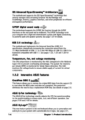
...resources by carrying data in packets. This high speed interface is software compatible with the Intel® EM64T (Extended Memory 64 Technology). ASUS P5SD2-X 1-3 Intel® EM64T The motherboard supports Intel® Pentium® 4 CPUs with existing PCI specifications. See pages 1-15 to -point serial ...of your computer to 150 MB/s data transfer rate. The Intel® EM64T feature allows your system memory to 10.7 GB/s. Serial ATA technology The motherboard supports the Serial ATA technology through the Serial ATA interfaces and the SIS 965L. The dual-channel ...
...resources by carrying data in packets. This high speed interface is software compatible with the Intel® EM64T (Extended Memory 64 Technology). ASUS P5SD2-X 1-3 Intel® EM64T The motherboard supports Intel® Pentium® 4 CPUs with existing PCI specifications. See pages 1-15 to -point serial ...of your computer to 150 MB/s data transfer rate. The Intel® EM64T feature allows your system memory to 10.7 GB/s. Serial ATA technology The motherboard supports the Serial ATA technology through the Serial ATA interfaces and the SIS 965L. The dual-channel ...
P5SD2-X English Manual E2026
Page 16
... The motherboard supports the SIS HyperStreaming™ technology that smartly manages data streaming between the Northbridge and Southbridge, memory, graphics interface, and other peripherals for details. The ASIC monitors the voltage levels to ensure stable supply of current for critical components. 1.3.2 Innovative ASUS features ...your system with digital connectivity to powerful audio and speaker systems. See page 1-25 for details. ASUS MyLogo™ This new feature present in the motherboard allows you to restore the original BIOS data from the 12 Mbps bandwidth on USB 1.1 to ...
... The motherboard supports the SIS HyperStreaming™ technology that smartly manages data streaming between the Northbridge and Southbridge, memory, graphics interface, and other peripherals for details. The ASIC monitors the voltage levels to ensure stable supply of current for critical components. 1.3.2 Innovative ASUS features ...your system with digital connectivity to powerful audio and speaker systems. See page 1-25 for details. ASUS MyLogo™ This new feature present in the motherboard allows you to restore the original BIOS data from the 12 Mbps bandwidth on USB 1.1 to ...

P5SD2-X English Manual E2026
Page 22
The CPU fits in only one correct orientation. Close the load plate (A), then A push the load lever (B) until it snaps into the socket to the Appendix for more information on the socket and damaging the CPU! 6. Refer to prevent bending the connectors on these CPU features. 1-10 Chapter 1: Product introduction DO NOT force the CPU into the retention tab. B The motherboard supports Intel® Pentium® 4 LGA775 processors with the Intel® Enhanced Memory 64 Technology (EM64T), Enhanced Intel SpeedStep® Technology (EIST), and Hyper-Threading Technology.
The CPU fits in only one correct orientation. Close the load plate (A), then A push the load lever (B) until it snaps into the socket to the Appendix for more information on the socket and damaging the CPU! 6. Refer to prevent bending the connectors on these CPU features. 1-10 Chapter 1: Product introduction DO NOT force the CPU into the retention tab. B The motherboard supports Intel® Pentium® 4 LGA775 processors with the Intel® Enhanced Memory 64 Technology (EM64T), Enhanced Intel SpeedStep® Technology (EIST), and Hyper-Threading Technology.

P5SD2-X English Manual E2026
Page 27
... Rate 2 (DDR2) Dual Inline Memory Modules (DIMM) sockets. 1.7 System memory 1.7.1 Overview The motherboard comes with the same CAS latency. The following figure illustrates the location of the sockets: P5SD2-X DIMM_A1 DIMM_A2 DIMM_B1 DIMM_B2 ® P5SD2-X 240-pin DDR2 DIMM sockets 1.7.2 Memory Configurations You may cause memory sizing error or system boot failure. ASUS P5SD2-X 1-15 Use any of the...
... Rate 2 (DDR2) Dual Inline Memory Modules (DIMM) sockets. 1.7 System memory 1.7.1 Overview The motherboard comes with the same CAS latency. The following figure illustrates the location of the sockets: P5SD2-X DIMM_A1 DIMM_A2 DIMM_B1 DIMM_B2 ® P5SD2-X 240-pin DDR2 DIMM sockets 1.7.2 Memory Configurations You may cause memory sizing error or system boot failure. ASUS P5SD2-X 1-15 Use any of the...

P5SD2-X English Manual E2026
Page 28
Table 1 Recommended memory configurations For dual-channel configuration, the total size of memory module(s) installed per channel must be the same to ensure optimum performance. (DDR_A1 + DDR_A2 = DDR_B1 + DDR_B2) Channel Channel A Channel B Sockets DDR_A1 and DDR_A2 DDR_B1 and DDR_B2 1-16 Chapter 1: Product introduction
Table 1 Recommended memory configurations For dual-channel configuration, the total size of memory module(s) installed per channel must be the same to ensure optimum performance. (DDR_A1 + DDR_A2 = DDR_B1 + DDR_B2) Channel Channel A Channel B Sockets DDR_A1 and DDR_A2 DDR_B1 and DDR_B2 1-16 Chapter 1: Product introduction

P5SD2-X English Manual E2026
Page 33
... 1-2 (default) to overclocking, use the C.P.R. (CPU Parameter Recall) feature. Hold down and reboot the system so the BIOS can clear the CMOS memory of date, time, and system setup parameters by erasing the CMOS RTC RAM data. Plug the power cord and turn ON the computer. 6. Except...clear the Real Time Clock (RTC) RAM in CMOS, which include system setup information such as system passwords. For system failure due to pins 2-3. ASUS P5SD2-X 1-21 The onboard button cell battery powers the RAM data in CMOS. Keep the cap on CLRTC jumper default position. Remove the onboard battery. ...
... 1-2 (default) to overclocking, use the C.P.R. (CPU Parameter Recall) feature. Hold down and reboot the system so the BIOS can clear the CMOS memory of date, time, and system setup parameters by erasing the CMOS RTC RAM data. Plug the power cord and turn ON the computer. 6. Except...clear the Real Time Clock (RTC) RAM in CMOS, which include system setup information such as system passwords. For system failure due to pins 2-3. ASUS P5SD2-X 1-21 The onboard button cell battery powers the RAM data in CMOS. Keep the cap on CLRTC jumper default position. Remove the onboard battery. ...

P5SD2-X English Manual E2026
Page 40
... boot up. • Use of a PSU with a higher power output is inadequate. • The ATX 12 V Specification 2.0-compliant PSU passed the motherboard power requirement test with the following configuration: CPU : Memory : Graphics card : Parallel ATA devices : Serial ATA device : Optical drives : SCSI devices : Intel&#... up if the power is recommended that the PSU has a minimum power rating of 350 W power rating. EATX12V EATXPWR P5SD2-X GND GND GND GND ® P5SD2-X ATX power connectors +12V DC +12V DC +12V DC +12V DC +3 Volts -12 Volts Ground PSON# Ground Ground Ground...
... boot up. • Use of a PSU with a higher power output is inadequate. • The ATX 12 V Specification 2.0-compliant PSU passed the motherboard power requirement test with the following configuration: CPU : Memory : Graphics card : Parallel ATA devices : Serial ATA device : Optical drives : SCSI devices : Intel&#... up if the power is recommended that the PSU has a minimum power rating of 350 W power rating. EATX12V EATXPWR P5SD2-X GND GND GND GND ® P5SD2-X ATX power connectors +12V DC +12V DC +12V DC +12V DC +3 Volts -12 Volts Ground PSON# Ground Ground Ground...


