
Motherboard Installation Guide
Page 5
... 4-22 4.4.5 Chipset 4-24 4.4.6 Onboard Devices Configuration 4-27 4.4.7 PCI PnP 4-28 4.5 Power menu 4-29 4.5.1 Suspend Mode 4-29 4.5.2 Repost Video on S3 Resume 4-29 4.5.3 ACPI 2.0 Support 4-29 4.5.4 ACPI APIC Support 4-29 4.5.5 APM Configuration 4-30 4.5.6 Hardware Monitor 4-32 4.6 Boot menu 4-33 4.6.1 Boot Device Priority 4-33 4.6.2 Boot Settings Configuration 4-34 4.6.3 Security 4-35 4.7 Exit menu 4-37 Chapter...
... 4-22 4.4.5 Chipset 4-24 4.4.6 Onboard Devices Configuration 4-27 4.4.7 PCI PnP 4-28 4.5 Power menu 4-29 4.5.1 Suspend Mode 4-29 4.5.2 Repost Video on S3 Resume 4-29 4.5.3 ACPI 2.0 Support 4-29 4.5.4 ACPI APIC Support 4-29 4.5.5 APM Configuration 4-30 4.5.6 Hardware Monitor 4-32 4.6 Boot menu 4-33 4.6.1 Boot Device Priority 4-33 4.6.2 Boot Settings Configuration 4-34 4.6.3 Security 4-35 4.7 Exit menu 4-37 Chapter...

Motherboard Installation Guide
Page 9
... setup procedures that you need when installing and configuring the motherboard. These documents are also provided. • Chapter 5: Software support This chapter describes the contents of the switches, jumpers, and connectors on ASUS hardware and software products. Refer to change system settings through the BIOS Setup menus. About this guide is organized...
... setup procedures that you need when installing and configuring the motherboard. These documents are also provided. • Chapter 5: Software support This chapter describes the contents of the switches, jumpers, and connectors on ASUS hardware and software products. Refer to change system settings through the BIOS Setup menus. About this guide is organized...

Motherboard Installation Guide
Page 11
... controller Supports Marvell® Virtual Cable Tester technology Supports POST Network-diagnostic program ASUS AI Booster ASUS AI NOS (Non-delay Overclocking System) feature ASUS AI Overclocking (Intelligent CPU frequency tuner) ASUS C.P.R. ...(CPU Parameter Recall) CPU, Memory, and PCI Express voltage adjustable Stepless Frequency Selection(SFS) from 100 MHz up to 400 MHz at 1 MHz increment Adjustable FSB/DDR ratio with more than two hard disk drives. P5RD1...
... controller Supports Marvell® Virtual Cable Tester technology Supports POST Network-diagnostic program ASUS AI Booster ASUS AI NOS (Non-delay Overclocking System) feature ASUS AI Overclocking (Intelligent CPU frequency tuner) ASUS C.P.R. ...(CPU Parameter Recall) CPU, Memory, and PCI Express voltage adjustable Stepless Frequency Selection(SFS) from 100 MHz up to 400 MHz at 1 MHz increment Adjustable FSB/DDR ratio with more than two hard disk drives. P5RD1...

Motherboard Installation Guide
Page 12
xii P5RD1-V specifications summary ASUS Special features BIOS features Rear panel Internal connectors Power requirement Form Factor Support CD contents ASUS Q-Fan2 ASUS CrashFree BIOS 2 ASUS MyLogo2 4 MB Flash ROM, AMI BIOS, PnP, DMI2.0, SM BIOS 2.3, WfM2.0 1 x Parallel port 1 x VGA port 1 x LAN (RJ-45) port 4 x USB 2.0 ports 1 x PS/2 keyboard port 1 ... (with 24-pin and 4-pin 12 V plugs) ATX 12 V 2.0 compliant ATX form factor: 12 in x 9.6 in (30.5 cm x 24.4 cm) Device drivers ASUS PC Probe ASUS Live Update Utility Anti-virus utility *Specifications are subject to change without notice.
xii P5RD1-V specifications summary ASUS Special features BIOS features Rear panel Internal connectors Power requirement Form Factor Support CD contents ASUS Q-Fan2 ASUS CrashFree BIOS 2 ASUS MyLogo2 4 MB Flash ROM, AMI BIOS, PnP, DMI2.0, SM BIOS 2.3, WfM2.0 1 x Parallel port 1 x VGA port 1 x LAN (RJ-45) port 4 x USB 2.0 ports 1 x PS/2 keyboard port 1 ... (with 24-pin and 4-pin 12 V plugs) ATX 12 V 2.0 compliant ATX form factor: 12 in x 9.6 in (30.5 cm x 24.4 cm) Device drivers ASUS PC Probe ASUS Live Update Utility Anti-virus utility *Specifications are subject to change without notice.

Motherboard Installation Guide
Page 13
This chapter describes the motherboard features and the new technologies it supports. 1Product introduction
This chapter describes the motherboard features and the new technologies it supports. 1Product introduction
Motherboard Installation Guide
Page 15
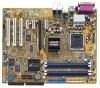
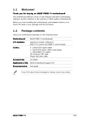
... an ASUS® P5RD1-V motherboard! Before you for the following items. Motherboard ASUS P5RD1-V motherboard I/O modules Serial port module (COM port) USB 2.0 (2 ports) and GAME (1 port) module Cables 2 x Serial ATA signal cables 1 x Serial ATA power cables (dual plugs) 1 x Ultra DMA/133 cables 40-conductor IDE cable Floppy disk drive cable Accessories I/O shield A p p l i c a t i o n C D s ASUS motherboard support CD...
... an ASUS® P5RD1-V motherboard! Before you for the following items. Motherboard ASUS P5RD1-V motherboard I/O modules Serial port module (COM port) USB 2.0 (2 ports) and GAME (1 port) module Cables 2 x Serial ATA signal cables 1 x Serial ATA power cables (dual plugs) 1 x Ultra DMA/133 cables 40-conductor IDE cable Floppy disk drive cable Accessories I/O shield A p p l i c a t i o n C D s ASUS motherboard support CD...

Motherboard Installation Guide
Page 16
...sixth generation I/O controller hub that allows you to 150 MB/s data transfer rate. TV-out support The motherboard comes with 800/533 MHz Front Side Bus (FSB). The motherboard also supports the Intel® Hyper-Threading Technology, Enhanced Intel SpeedStep® Technology, and is fully ...174; XPRESS 200 Northbridge integrates the RADEON® X300, an integrated graphics processing unit (GPU) for details. Serial ATA technology The motherboard supports the Serial ATA technology through the Serial ATA interfaces and the ULI® M1573. See page 2-6 for details. See page 4-23 and ...
...sixth generation I/O controller hub that allows you to 150 MB/s data transfer rate. TV-out support The motherboard comes with 800/533 MHz Front Side Bus (FSB). The motherboard also supports the Intel® Hyper-Threading Technology, Enhanced Intel SpeedStep® Technology, and is fully ...174; XPRESS 200 Northbridge integrates the RADEON® X300, an integrated graphics processing unit (GPU) for details. Serial ATA technology The motherboard supports the Serial ATA technology through the Serial ATA interfaces and the ULI® M1573. See page 2-6 for details. See page 4-23 and ...

Motherboard Installation Guide
Page 17
PCI Express™ interface The motherboard fully supports PCI Express, the latest I /O) to -point serial interconnections between devices and allows higher clockspeeds by the ASIC (integrated in packets. This CODEC is fully-compliant...-clear digital audio. See pages 2-26 and 5-16 for critical components. Temperature, fan, and voltage monitoring The CPU temperature is monitored for four SATA connectors. ASUS P5RD1-V 1-3 Onboard RAID solution The onboard ULI® M1573 allows RAID 0, RAID 1, RAID 0+1, or JBOD configuration for timely failure detection. The system fan rotations per ...
PCI Express™ interface The motherboard fully supports PCI Express, the latest I /O) to -point serial interconnections between devices and allows higher clockspeeds by the ASIC (integrated in packets. This CODEC is fully-compliant...-clear digital audio. See pages 2-26 and 5-16 for critical components. Temperature, fan, and voltage monitoring The CPU temperature is monitored for four SATA connectors. ASUS P5RD1-V 1-3 Onboard RAID solution The onboard ULI® M1573 allows RAID 0, RAID 1, RAID 0+1, or JBOD configuration for timely failure detection. The system fan rotations per ...

Motherboard Installation Guide
Page 18
... allows you to the LAN (RJ-45) port(s). ASUS MyLogo2™ This new feature present in the motherboard allows you can easily monitor the condition of the Ethernet cable(s) connected to restore the original BIOS data from the support CD in case when the BIOS codes and data are... corrupted. 1.3.2 ASUS Proactive features AI NOS™ (Non-Delay Overclocking System) ASUS Non-delay Overclocking System™ (NOS) is a BIOS-based diagnostic tool that ...
... allows you to the LAN (RJ-45) port(s). ASUS MyLogo2™ This new feature present in the motherboard allows you can easily monitor the condition of the Ethernet cable(s) connected to restore the original BIOS data from the support CD in case when the BIOS codes and data are... corrupted. 1.3.2 ASUS Proactive features AI NOS™ (Non-Delay Overclocking System) ASUS Non-delay Overclocking System™ (NOS) is a BIOS-based diagnostic tool that ...

Motherboard Installation Guide
Page 28
The CPU fits in only one correct orientation. Close the load plate (A), then A push the load lever (B) until it snaps into the socket to the Appendix for more information on the socket and damaging the CPU! 6. DO NOT force the CPU into the retention tab. B The motherboard supports Intel® Pentium® 4 LGA775 processors with the Intel® Enhanced Intel SpeedStep® Technology (EIST) and Intel® Hyper-Threading Technology. Refer to prevent bending the connectors on these CPU features. 2-8 Chapter 2: Hardware information
The CPU fits in only one correct orientation. Close the load plate (A), then A push the load lever (B) until it snaps into the socket to the Appendix for more information on the socket and damaging the CPU! 6. DO NOT force the CPU into the retention tab. B The motherboard supports Intel® Pentium® 4 LGA775 processors with the Intel® Enhanced Intel SpeedStep® Technology (EIST) and Intel® Hyper-Threading Technology. Refer to prevent bending the connectors on these CPU features. 2-8 Chapter 2: Hardware information

Motherboard Installation Guide
Page 34
... TwinMOS 512MB TwinMOS 256MB TwinMOS 512MB TwinMOS 256MB Transcend 512MB Transcend 1024MB Transcend 256MB Apacer 512MB Apacer 256MB Apacer 512MB Apacer 256MB A DATA Model DIMM support Brand Side(s) Component ABC KVR400X64C3A/256 Hynix SS HY5DU56822BT-D43 •• KVR400X64C3A/512 Hynix DS HY5DU56822BT-D43 • • • KVR400X64C3A/256 Infineon SS...
... TwinMOS 512MB TwinMOS 256MB TwinMOS 512MB TwinMOS 256MB Transcend 512MB Transcend 1024MB Transcend 256MB Apacer 512MB Apacer 256MB Apacer 512MB Apacer 256MB A DATA Model DIMM support Brand Side(s) Component ABC KVR400X64C3A/256 Hynix SS HY5DU56822BT-D43 •• KVR400X64C3A/512 Hynix DS HY5DU56822BT-D43 • • • KVR400X64C3A/256 Infineon SS...

Motherboard Installation Guide
Page 35
Double-sided ASUS P5RD1-V 2-15 supports on pair of modules inserted into the blue and black slots as one pair of Dual-channel memory configuration. support for 4 modules inserted into either slot, in a Single-channel memory configuration. Single-sided ... MD44512VIT3208GATA03 V826632K24SCTG-D0 V826664K24SCTG-D0 AL5D8C53T-5B1T AL6D8C53T-5B1T GL5123200DC GL1GB3200DC GLX2563200UP GD3200-512DC BL3264Z402.8TG 96M425653CE-40TB6 AED560UD00-500C88X DIMM support Brand Side(s) Component ABC SAMSUNG DS K4H560838F-TCCC • • • Hynix SS HY5DU56822CT-D43 • •...
Double-sided ASUS P5RD1-V 2-15 supports on pair of modules inserted into the blue and black slots as one pair of Dual-channel memory configuration. support for 4 modules inserted into either slot, in a Single-channel memory configuration. Single-sided ... MD44512VIT3208GATA03 V826632K24SCTG-D0 V826664K24SCTG-D0 AL5D8C53T-5B1T AL6D8C53T-5B1T GL5123200DC GL1GB3200DC GLX2563200UP GD3200-512DC BL3264Z402.8TG 96M425653CE-40TB6 AED560UD00-500C88X DIMM support Brand Side(s) Component ABC SAMSUNG DS K4H560838F-TCCC • • • Hynix SS HY5DU56822CT-D43 • •...

Motherboard Installation Guide
Page 36
... that it flips out with your fingers when pressing the retaining clips. Simultaneously press the retaining clips outward to unlock the DIMM. 1 1 DDR DIMM notch Support the DIMM lightly with extra force. 2. Failure to do so may cause severe damage to remove a DIMM. 2 1. Firmly insert the DIMM into a socket to unplug...
... that it flips out with your fingers when pressing the retaining clips. Simultaneously press the retaining clips outward to unlock the DIMM. 1 1 DDR DIMM notch Support the DIMM lightly with extra force. 2. Failure to do so may cause severe damage to remove a DIMM. 2 1. Firmly insert the DIMM into a socket to unplug...

Motherboard Installation Guide
Page 37
... until the card is already installed in a chassis). 3. Secure the card to install expansion cards. Install the software drivers for information on the next page. 3. ASUS P5RD1-V 2-17 Remove the system unit cover (if your motherboard is completely seated on the system and change the necessary BIOS settings, if any. Remove the... card To install an expansion card: 1. See Chapter 4 for the expansion card. The following sub-sections describe the slots and the expansion cards that they support. Refer to use . 4.
... until the card is already installed in a chassis). 3. Secure the card to install expansion cards. Install the software drivers for information on the next page. 3. ASUS P5RD1-V 2-17 Remove the system unit cover (if your motherboard is completely seated on the system and change the necessary BIOS settings, if any. Remove the... card To install an expansion card: 1. See Chapter 4 for the expansion card. The following sub-sections describe the slots and the expansion cards that they support. Refer to use . 4.

Motherboard Installation Guide
Page 38
... shared shared shared - - - IRQ assignments for ISA or PCI devices. shared shared shared - - - shared When using PCI cards on shared slots, ensure that the drivers support "Share IRQ" or that the cards do not need IRQ assignments. shared - - - - - Otherwise, conflicts will arise between the two PCI groups, making the system unstable...
... shared shared shared - - - IRQ assignments for ISA or PCI devices. shared shared shared - - - shared When using PCI cards on shared slots, ensure that the drivers support "Share IRQ" or that the cards do not need IRQ assignments. shared - - - - - Otherwise, conflicts will arise between the two PCI groups, making the system unstable...

Motherboard Installation Guide
Page 39
ASUS P5RD1-V 2-19 The figure shows a graphics card installed on the PCI Express x16 slot. 2.5.6 PCI Express x1 slot This motherboard supports PCI Express x1 network cards, SCSI cards and other cards that comply with PCI specifications. 2.5.4 PCI slots The PCI slots support cards such as a LAN card, ...with the PCI Express specifications. The figure shows a network card installed on a PCI slot. 2.5.5 PCI Express x16 slot This motherboard supports PCI Express x16 graphic cards that comply with the PCI Express specifications. The figure shows a LAN card installed on the PCI Express x1 ...
ASUS P5RD1-V 2-19 The figure shows a graphics card installed on the PCI Express x16 slot. 2.5.6 PCI Express x1 slot This motherboard supports PCI Express x1 network cards, SCSI cards and other cards that comply with PCI specifications. 2.5.4 PCI slots The PCI slots support cards such as a LAN card, ...with the PCI Express specifications. The figure shows a network card installed on a PCI slot. 2.5.5 PCI Express x16 slot This motherboard supports PCI Express x16 graphic cards that comply with the PCI Express specifications. The figure shows a LAN card installed on the PCI Express x1 ...

Motherboard Installation Guide
Page 47
... CHA_FAN1 PWR_FAN CPU_FAN CPU FAN PWM CPU FAN IN CPU FAN PWR CHA_FAN1 Rotation +12V GND PWR_FAN GND +12V Rotation P5RD1-V Fan connectors ASUS P5RD1-V 2-27 4 . Lack of 1A~3.48A (41.76 W max.) at +12V. These are not jumpers! DO NOT place jumper caps on the motherboard, ... forget to connect the fan cables to the fan connectors. Connect the fan cables to the fan connectors on the fan connectors! • The ASUS Q-Fan2 function is supported using the CPU Fan (CPU_FAN) and Chassis Fan 1 (CHA_FAN1) connectors only. CPU, Chassis, and Power fan connectors (4-pin CPU_FAN, 3-pin ...
... CHA_FAN1 PWR_FAN CPU_FAN CPU FAN PWM CPU FAN IN CPU FAN PWR CHA_FAN1 Rotation +12V GND PWR_FAN GND +12V Rotation P5RD1-V Fan connectors ASUS P5RD1-V 2-27 4 . Lack of 1A~3.48A (41.76 W max.) at +12V. These are not jumpers! DO NOT place jumper caps on the motherboard, ... forget to connect the fan cables to the fan connectors. Connect the fan cables to the fan connectors on the fan connectors! • The ASUS Q-Fan2 function is supported using the CPU Fan (CPU_FAN) and Chassis Fan 1 (CHA_FAN1) connectors only. CPU, Chassis, and Power fan connectors (4-pin CPU_FAN, 3-pin ...

Motherboard Installation Guide
Page 48
... port connector 6 . These USB connectors comply with USB 2.0 specification that supports up to the USB connectors. USB+5V USB_P6USB_P6+ GND NC USB+5V USB_P8USB_P8+ GND NC P5RD1-V ® USB78 1 USB56 1 USB+5V USB_P5USB_P5+ GND USB+5V USB_P7USB_P7+ GND P5RD1-V USB 2.0 connectors Never connect a 1 3 9 4 c a b l e to 480 Mbps connection speed. Connect the serial port module...
... port connector 6 . These USB connectors comply with USB 2.0 specification that supports up to the USB connectors. USB+5V USB_P6USB_P6+ GND NC USB+5V USB_P8USB_P8+ GND NC P5RD1-V ® USB78 1 USB56 1 USB+5V USB_P5USB_P5+ GND USB+5V USB_P7USB_P7+ GND P5RD1-V USB 2.0 connectors Never connect a 1 3 9 4 c a b l e to 480 Mbps connection speed. Connect the serial port module...

Motherboard Installation Guide
Page 51
...sensor or switch cable to this connector when a chassis component is then generated as a chassis intrusion event. ASUS P5RD1-V 2-31 CHASSIS +5VSB_MB Chassis Signal GND P5RD1-V ® (Default) P5RD1-V Chassis intrusion connector 11. By default, the pins labeled "Chassis Signal" and "Ground" are shorted with... AC'97-compliant pin definition AGND NC NC NC P5RD1-V ® AAFP MIC2 MICPWR Line out_R NC Line out_L PORT1 L PORT1 R PORT2 R SENSE_SEND PORT2 L P5RD1-V Analog front panel connector • Use a chassis that supports either HD Audio or legacy AC '97 audio standard...
...sensor or switch cable to this connector when a chassis component is then generated as a chassis intrusion event. ASUS P5RD1-V 2-31 CHASSIS +5VSB_MB Chassis Signal GND P5RD1-V ® (Default) P5RD1-V Chassis intrusion connector 11. By default, the pins labeled "Chassis Signal" and "Ground" are shorted with... AC'97-compliant pin definition AGND NC NC NC P5RD1-V ® AAFP MIC2 MICPWR Line out_R NC Line out_L PORT1 L PORT1 R PORT2 R SENSE_SEND PORT2 L P5RD1-V Analog front panel connector • Use a chassis that supports either HD Audio or legacy AC '97 audio standard...

Motherboard Installation Guide
Page 53
...Connect the HDD Activity LED cable to this connector. PLED SPEAKER PLED+ PLED+5V Ground Ground Speaker P5RD1-V ® PANEL IDE_LED+ IDE_LED- The IDE LED lights up when you to this connector. ASUS P5RD1-V 2-33 Refer to the HDD. • System warning speaker (Orange 4-pin SPEAKER) This ...2-pin IDE_LED) This 2-pin connector is for the chassis-mounted system warning speaker. System panel connector (20-pin PANEL) This connector supports several chassis-mounted functions. The system power LED lights up or flashes when data is read from or written to the connector description...
...Connect the HDD Activity LED cable to this connector. PLED SPEAKER PLED+ PLED+5V Ground Ground Speaker P5RD1-V ® PANEL IDE_LED+ IDE_LED- The IDE LED lights up when you to this connector. ASUS P5RD1-V 2-33 Refer to the HDD. • System warning speaker (Orange 4-pin SPEAKER) This ...2-pin IDE_LED) This 2-pin connector is for the chassis-mounted system warning speaker. System panel connector (20-pin PANEL) This connector supports several chassis-mounted functions. The system power LED lights up or flashes when data is read from or written to the connector description...


