
Motherboard Installation Guide
Page 4
... the computer 3-2 3.2.1 Using the OS shut down function 3-2 3.2.2 Using the dual function power switch 3-2 Chapter 4: BIOS setup 4.1 Managing and updating your BIOS 4-1 4.1.1 Creating a bootable floppy disk 4-1 4.1.2 AFUDOS utility 4-2 4.1.3 ASUS CrashFree BIOS 2 utility 4-5 4.1.4 ASUS EZ Flash utility 4-7 4.1.5 ASUS Update utility 4-8 4.2 BIOS setup program 4-11 4.2.1 BIOS menu screen 4-12 4.2.2 Menu bar 4-12 4.2.3 Navigation keys 4-12 4.2.4 Menu items 4-13 4.2.5 Sub-menu...
... the computer 3-2 3.2.1 Using the OS shut down function 3-2 3.2.2 Using the dual function power switch 3-2 Chapter 4: BIOS setup 4.1 Managing and updating your BIOS 4-1 4.1.1 Creating a bootable floppy disk 4-1 4.1.2 AFUDOS utility 4-2 4.1.3 ASUS CrashFree BIOS 2 utility 4-5 4.1.4 ASUS EZ Flash utility 4-7 4.1.5 ASUS Update utility 4-8 4.2 BIOS setup program 4-11 4.2.1 BIOS menu screen 4-12 4.2.2 Menu bar 4-12 4.2.3 Navigation keys 4-12 4.2.4 Menu items 4-13 4.2.5 Sub-menu...

Motherboard Installation Guide
Page 9
...more information Refer to change system settings through the BIOS Setup menus. ix Detailed descriptions of the BIOS parameters are not part of the standard package. It includes description of the switches, jumpers, and connectors on ASUS hardware and software products. How this guide This user... The ASUS website provides updated information on the motherboard. • Chapter 3: Powering up This chapter describes the power up sequence, the vocal POST messages, and ways of shutting down the system. • Chapter 4: BIOS setup This chapter tells how to the following parts: •...
...more information Refer to change system settings through the BIOS Setup menus. ix Detailed descriptions of the BIOS parameters are not part of the standard package. It includes description of the switches, jumpers, and connectors on ASUS hardware and software products. How this guide This user... The ASUS website provides updated information on the motherboard. • Chapter 3: Powering up This chapter describes the power up sequence, the vocal POST messages, and ways of shutting down the system. • Chapter 4: BIOS setup This chapter tells how to the following parts: •...

Motherboard Installation Guide
Page 12
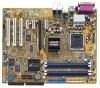
P5RD1-V specifications summary ASUS Special features BIOS features Rear panel Internal connectors Power requirement Form Factor Support CD contents ASUS Q-Fan2 ASUS CrashFree BIOS 2 ASUS MyLogo2 4 MB Flash ROM, AMI BIOS, PnP, DMI2.0, SM BIOS 2.3, WfM2.0 1 x Parallel port 1 x VGA port 1 x LAN (RJ-45) port 4 x USB 2.0 ports 1 x PS/2 keyboard port 1 x PS/2 mouse port 8-channel ...V plugs) ATX 12 V 2.0 compliant ATX form factor: 12 in x 9.6 in (30.5 cm x 24.4 cm) Device drivers ASUS PC Probe ASUS Live Update Utility Anti-virus utility *Specifications are subject to change without notice. xii
P5RD1-V specifications summary ASUS Special features BIOS features Rear panel Internal connectors Power requirement Form Factor Support CD contents ASUS Q-Fan2 ASUS CrashFree BIOS 2 ASUS MyLogo2 4 MB Flash ROM, AMI BIOS, PnP, DMI2.0, SM BIOS 2.3, WfM2.0 1 x Parallel port 1 x VGA port 1 x LAN (RJ-45) port 4 x USB 2.0 ports 1 x PS/2 keyboard port 1 x PS/2 mouse port 8-channel ...V plugs) ATX 12 V 2.0 compliant ATX form factor: 12 in x 9.6 in (30.5 cm x 24.4 cm) Device drivers ASUS PC Probe ASUS Live Update Utility Anti-virus utility *Specifications are subject to change without notice. xii

Motherboard Installation Guide
Page 18
... a technology that detects and reports Ethernet cable faults and shorts. ASUS MyLogo2™ This new feature present in case when the BIOS codes and data are corrupted. See details on page 4-5. ASUS Q-Fan 2 technology The ASUS Q-Fan 2 technology smartly adjusts the fan speeds according to the... system loading to your system with customizable boot logos. 1.3.2 ASUS Proactive features AI NOS™ (Non-Delay Overclocking System) ASUS Non-delay Overclocking System™ (NOS) is a BIOS-based diagnostic tool that auto-detects the CPU loading and dynamically overclocks the...
... a technology that detects and reports Ethernet cable faults and shorts. ASUS MyLogo2™ This new feature present in case when the BIOS codes and data are corrupted. See details on page 4-5. ASUS Q-Fan 2 technology The ASUS Q-Fan 2 technology smartly adjusts the fan speeds according to the... system loading to your system with customizable boot logos. 1.3.2 ASUS Proactive features AI NOS™ (Non-Delay Overclocking System) ASUS Non-delay Overclocking System™ (NOS) is a BIOS-based diagnostic tool that auto-detects the CPU loading and dynamically overclocks the...

Motherboard Installation Guide
Page 37
..., if any. Secure the card to the chassis with it by adjusting the software settings. 1. Turn on BIOS setup. 2. Install the software drivers for the card. 2. Remove the system unit cover (if your motherboard is completely seated on the next page. 3. 2.5 ... IRQ to install expansion cards. Refer to unplug the power cord before adding or removing expansion cards. Make sure to the tables on the slot. 5. ASUS P5RD1-V 2-17 Align the card connector with the slot and press firmly until the card is already installed in a chassis). 3. See Chapter 4 for later use ...
..., if any. Secure the card to the chassis with it by adjusting the software settings. 1. Turn on BIOS setup. 2. Install the software drivers for the card. 2. Remove the system unit cover (if your motherboard is completely seated on the next page. 3. 2.5 ... IRQ to install expansion cards. Refer to unplug the power cord before adding or removing expansion cards. Make sure to the tables on the slot. 5. ASUS P5RD1-V 2-17 Align the card connector with the slot and press firmly until the card is already installed in a chassis). 3. See Chapter 4 for later use ...
Motherboard Installation Guide
Page 40
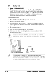
... seconds, then move the cap back to clear the Real Time Clock (RTC) RAM in CMOS, which include system setup information such as system passwords. P5RD1-V ® P5RD1-V Clear RTC RAM CLRTC 2 1 Normal (Default) 3 2 Clear CMOS You do not need to clear the RTC when the system hangs due to pins 2-3.... Move the jumper cap from pins 1-2 (default) to overclocking. Hold down and reboot the system so the BIOS can clear the CMOS memory of date, time, and...
... seconds, then move the cap back to clear the Real Time Clock (RTC) RAM in CMOS, which include system setup information such as system passwords. P5RD1-V ® P5RD1-V Clear RTC RAM CLRTC 2 1 Normal (Default) 3 2 Clear CMOS You do not need to clear the RTC when the system hangs due to pins 2-3.... Move the jumper cap from pins 1-2 (default) to overclocking. Hold down and reboot the system so the BIOS can clear the CMOS memory of date, time, and...

Motherboard Installation Guide
Page 46
... GND RSATA_TXP3 RSATA_TXN3 GND RSATA_RXP3 RSATA_RXN3 GND P5RD1-V SATA connectors SATA1 GND RSATA_TXP1 RSATA_TXN1 GND RSATA_RXP1 RSATA_RXN1 GND SATA4 GND RSATA_TXP4 RSATA_TXN4 GND RSATA_RXP4 RSATA_RXN4 GND SATA2 GND RSATA_TXP2 RSATA_TXN2 GND RSATA_RXP2 RSATA_RXN2 ... you installed Serial ATA hard disk drives, you cannot configure a RAID 0 set up Serial ATA RAID configurations. Enable the Serial ATA Controller item in the BIOS if you want to set or JBOD with more than two hard disk drives. • Install the Windows® 2000 Service Pack 4 or the Windows...
... GND RSATA_TXP3 RSATA_TXN3 GND RSATA_RXP3 RSATA_RXN3 GND P5RD1-V SATA connectors SATA1 GND RSATA_TXP1 RSATA_TXN1 GND RSATA_RXP1 RSATA_RXN1 GND SATA4 GND RSATA_TXP4 RSATA_TXN4 GND RSATA_RXP4 RSATA_RXN4 GND SATA2 GND RSATA_TXP2 RSATA_TXN2 GND RSATA_RXP2 RSATA_RXN2 ... you installed Serial ATA hard disk drives, you cannot configure a RAID 0 set up Serial ATA RAID configurations. Enable the Serial ATA Controller item in the BIOS if you want to set or JBOD with more than two hard disk drives. • Install the Windows® 2000 Service Pack 4 or the Windows...

Motherboard Installation Guide
Page 51
Chassis intrusion connector (4-1 pin CHASSIS) This connector is for a chassis-mounted front panel audio I N K A in the BIOS to use the High-Definition (Azalia) audio features, set the A C 9 7 & A z a l i a L I /O module that supports either HD Audio or legacy AC '97 audio standard... cap. See page 4-26. Front panel audio connector (10-1 pin AAFP) This connector is legacy AC'97 audio, if you intend to Azalia. ASUS P5RD1-V 2-31 Connect one end of the front panel audio I/O module cable to this connector is for a chassis-mounted intrusion detection sensor or switch. Remove...
Chassis intrusion connector (4-1 pin CHASSIS) This connector is for a chassis-mounted front panel audio I N K A in the BIOS to use the High-Definition (Azalia) audio features, set the A C 9 7 & A z a l i a L I /O module that supports either HD Audio or legacy AC '97 audio standard... cap. See page 4-26. Front panel audio connector (10-1 pin AAFP) This connector is legacy AC'97 audio, if you intend to Azalia. ASUS P5RD1-V 2-31 Connect one end of the front panel audio I/O module cable to this connector is for a chassis-mounted intrusion detection sensor or switch. Remove...

Motherboard Installation Guide
Page 53
... system power LED lights up or flashes when data is for the chassis-mounted system warning speaker. PLED SPEAKER PLED+ PLED+5V Ground Ground Speaker P5RD1-V ® PANEL IDE_LED+ IDE_LED- The IDE LED lights up when you to hear system beeps and warnings. • Power/Soft-off the system...and blinks when the system is in SLEEP or SOFT-OFF mode depending on the BIOS settings. Pressing the power button turns the system ON or puts the system in sleep mode. • Hard disk drive activity (Red 2-pin IDE_LED) This 2-pin connector is for the HDD Activity LED. ASUS P5RD1-V 2-33
... system power LED lights up or flashes when data is for the chassis-mounted system warning speaker. PLED SPEAKER PLED+ PLED+5V Ground Ground Speaker P5RD1-V ® PANEL IDE_LED+ IDE_LED- The IDE LED lights up when you to hear system beeps and warnings. • Power/Soft-off the system...and blinks when the system is in SLEEP or SOFT-OFF mode depending on the BIOS settings. Pressing the power button turns the system ON or puts the system in sleep mode. • Hard disk drive activity (Red 2-pin IDE_LED) This 2-pin connector is for the HDD Activity LED. ASUS P5RD1-V 2-33

Motherboard Installation Guide
Page 57
...enter the BIOS Setup. The system then runs the power-on the system front panel case lights up when you turned on the power, the system may light up for assistance. System power 6. Monitor b. Check the jumper settings and connections or call your monitor complies with a surge protector. 5. ASUS P5RD1-V 3-1 For..., the system power LED on self tests or POST. At power on the devices in Chapter 4. After making all switches are running, the BIOS beeps (see anything within 30 seconds from the time you press the ATX power button. Turn on , hold down the key to the power...
...enter the BIOS Setup. The system then runs the power-on the system front panel case lights up when you turned on the power, the system may light up for assistance. System power 6. Monitor b. Check the jumper settings and connections or call your monitor complies with a surge protector. 5. ASUS P5RD1-V 3-1 For..., the system power LED on self tests or POST. At power on the devices in Chapter 4. After making all switches are running, the BIOS beeps (see anything within 30 seconds from the time you press the ATX power button. Turn on , hold down the key to the power...

Motherboard Installation Guide
Page 58
... sleep mode or to section "4.5 Power Menu" in Chapter 4 for less than four seconds lets the system enter the soft-off mode regardless of the BIOS setting. Click the S t a r t button then select T u r n O f f C o m p u t e r . 2. The power supply should turn off after Windows® shuts down. ... function power switch While the system is selected, then click the O K button to shut down the computer. 3. Refer to soft-off mode, depending on the BIOS setting. Click the S t a r t button then click S h u t D o w n . . . 2. 3.2 Powering off the computer 3.2.1 Using the OS shut down function...
... sleep mode or to section "4.5 Power Menu" in Chapter 4 for less than four seconds lets the system enter the soft-off mode regardless of the BIOS setting. Click the S t a r t button then select T u r n O f f C o m p u t e r . 2. The power supply should turn off after Windows® shuts down. ... function power switch While the system is selected, then click the O K button to shut down the computer. 3. Refer to soft-off mode, depending on the BIOS setting. Click the S t a r t button then click S h u t D o w n . . . 2. 3.2 Powering off the computer 3.2.1 Using the OS shut down function...

Motherboard Installation Guide
Page 59
This chapter tells how to change the system settings through the BIOS Setup menus. Detailed descriptions of the BIOS parameters are also provided. 4 BIOS setup
This chapter tells how to change the system settings through the BIOS Setup menus. Detailed descriptions of the BIOS parameters are also provided. 4 BIOS setup

Motherboard Installation Guide
Page 60
Chapter summary 4.1 Managing and updating your BIOS 4-1 4.2 BIOS setup program 4-11 4.3 Main menu 4-14 4.4 Advanced menu 4-17 4.5 Power menu 4-29 4.6 Boot menu 4-33 4.7 Exit menu 4-37 ASUS P5RD1-V
Chapter summary 4.1 Managing and updating your BIOS 4-1 4.2 BIOS setup program 4-11 4.3 Main menu 4-14 4.4 Advanced menu 4-17 4.5 Power menu 4-29 4.6 Boot menu 4-33 4.7 Exit menu 4-37 ASUS P5RD1-V

Motherboard Installation Guide
Page 61
... or the motherboard support CD.) 4. b. Windows® XP environment a. b. ASUS P5RD1-V 4-1 4.1 Managing and updating your BIOS The following to create a bootable floppy disk. A S U S E Z F l a s h (Updates the BIOS in DOS using the ASUS Update or AFUDOS utilities. 4.1.1 Creating a bootable floppy disk 1. Do either one of the original motherboard BIOS file to a bootable floppy disk in Windows® environment...
... or the motherboard support CD.) 4. b. Windows® XP environment a. b. ASUS P5RD1-V 4-1 4.1 Managing and updating your BIOS The following to create a bootable floppy disk. A S U S E Z F l a s h (Updates the BIOS in DOS using the ASUS Update or AFUDOS utilities. 4.1.1 Creating a bootable floppy disk 1. Do either one of the original motherboard BIOS file to a bootable floppy disk in Windows® environment...

Motherboard Installation Guide
Page 62
... for the main filename and three alphanumeric characters for Windows® 2000: a. c. e. A:\>afudos /oOLDBIOS1.ROM Main filename Extension name 4-2 Chapter 4: BIOS setup This utility also allows you created earlier. 2. Boot the system in DOS environment using the AFUDOS utility: • Make sure that the floppy...the prompt type: afudos /o[filename] where the [filename] is your optical drive. b. Insert the Windows® 2000 CD to update the BIOS file in DOS mode, then at least 1.2 MB free space to the bootable floppy disk you to continue. 2. Copy the original or the...
... for the main filename and three alphanumeric characters for Windows® 2000: a. c. e. A:\>afudos /oOLDBIOS1.ROM Main filename Extension name 4-2 Chapter 4: BIOS setup This utility also allows you created earlier. 2. Boot the system in DOS environment using the AFUDOS utility: • Make sure that the floppy...the prompt type: afudos /o[filename] where the [filename] is your optical drive. b. Insert the Windows® 2000 CD to update the BIOS file in DOS mode, then at least 1.2 MB free space to the bootable floppy disk you to continue. 2. Copy the original or the...

Motherboard Installation Guide
Page 63
...at the prompt type: afudos /i[filename] where [filename] is the latest or the original BIOS file on a piece of paper. Visit the ASUS website (www.asus.com) and download the latest BIOS file for the motherboard. A:\>afudos /oOLDBIOS1.ROM AMI Firmware Update Utility - All rights reserved... prompt. 2. Write the BIOS filename on the bootable floppy disk. The utility copies the current BIOS file to the DOS prompt after copying the current BIOS file. Reading flash ..... done Write to file ...ok A:\> The utility returns to the floppy disk. A:\>afudos /iP5RD1V.ROM ASUS P5RD1-V 4-3
...at the prompt type: afudos /i[filename] where [filename] is the latest or the original BIOS file on a piece of paper. Visit the ASUS website (www.asus.com) and download the latest BIOS file for the motherboard. A:\>afudos /oOLDBIOS1.ROM AMI Firmware Update Utility - All rights reserved... prompt. 2. Write the BIOS filename on the bootable floppy disk. The utility copies the current BIOS file to the DOS prompt after copying the current BIOS file. Reading flash ..... done Write to file ...ok A:\> The utility returns to the floppy disk. A:\>afudos /iP5RD1V.ROM ASUS P5RD1-V 4-3

Motherboard Installation Guide
Page 64
... disk drive. done Reading flash .... done Verifying flash ... The utility returns to prevent system boot failure! 5. 4. The utility reads the file and starts updating the BIOS. A:\>afudos /iP5RD1V.ROM AMI Firmware Update Utility - Version 1.19(ASUS V2.07(03.11.24BB)) Copyright (C) 2003 American Megatrends, Inc.
... disk drive. done Reading flash .... done Verifying flash ... The utility returns to prevent system boot failure! 5. 4. The utility reads the file and starts updating the BIOS. A:\>afudos /iP5RD1V.ROM AMI Firmware Update Utility - Version 1.19(ASUS V2.07(03.11.24BB)) Copyright (C) 2003 American Megatrends, Inc.

Motherboard Installation Guide
Page 65
... for the original or updated BIOS file. 4.1.3 ASUS CrashFree BIOS 2 utility The ASUS CrashFree BIOS 2 is an auto recovery tool that you to restore the BIOS file when it fails or gets corrupted during the updating process. Insert the floppy disk with the original or updated BIOS file to P 5 R D 1 V . Checking for floppy... ASUS P5RD1-V 4-5 When found ! Doing so can...
... for the original or updated BIOS file. 4.1.3 ASUS CrashFree BIOS 2 utility The ASUS CrashFree BIOS 2 is an auto recovery tool that you to restore the BIOS file when it fails or gets corrupted during the updating process. Insert the floppy disk with the original or updated BIOS file to P 5 R D 1 V . Checking for floppy... ASUS P5RD1-V 4-5 When found ! Doing so can...

Motherboard Installation Guide
Page 66
..., the utility automatically checks the optical drive for floppy... Starting BIOS recovery... Visit the ASUS website (www.asus.com) to the optical drive. 3. Remove any floppy disk from the support CD: 1. Checking for the original or updated BIOS file. CD-ROM found ! Bad BIOS checksum. Bad BIOS checksum. Completed. Restart the system after the utility completes...
..., the utility automatically checks the optical drive for floppy... Starting BIOS recovery... Visit the ASUS website (www.asus.com) to the optical drive. 3. Remove any floppy disk from the support CD: 1. Checking for the original or updated BIOS file. CD-ROM found ! Bad BIOS checksum. Bad BIOS checksum. Completed. Restart the system after the utility completes...

Motherboard Installation Guide
Page 67
..., then restart the system. 3. Completed. ASUS P5RD1-V 4-7 EZFlash starting BIOS update Checking for floppy... 4. Start erasing.......| Start programming...| Flashed successfully. Make sure that contains the BIOS file to the floppy disk drive. 4.1.4 ASUS EZ Flash utility The ASUS EZ Flash feature allows you rename the BIOS file to P5RD1V.ROM. Save the BIOS file to display the following...
..., then restart the system. 3. Completed. ASUS P5RD1-V 4-7 EZFlash starting BIOS update Checking for floppy... 4. Start erasing.......| Start programming...| Flashed successfully. Make sure that contains the BIOS file to the floppy disk drive. 4.1.4 ASUS EZ Flash utility The ASUS EZ Flash feature allows you rename the BIOS file to P5RD1V.ROM. Save the BIOS file to display the following...


