
User Manual
Page 31
Reading flash ..... All rights reserved. exe 2 DOS afudos /o[filename filename A:\>afudos /oOLDBIOS1.rom 3. 按下 afudos /oOLDBIOS1.rom AMI Firmware Update Utility - Version 1.19(ASUS V2.07(03.11.24BB)) Copyright (C) 2002 American Megatrends, Inc. BIOS 2.1 使用 AFUDOS BIOS AFUDOS DOS BIOS BIOS 程式。AFUDOS BIOS BIOS BIOS 程式 BIOS 程式。 1.2MB BIOS 1 AFUDOS 程式(afudos. done Write to file...... ok A:\> 當 BIOS DOS 31
Reading flash ..... All rights reserved. exe 2 DOS afudos /o[filename filename A:\>afudos /oOLDBIOS1.rom 3. 按下 afudos /oOLDBIOS1.rom AMI Firmware Update Utility - Version 1.19(ASUS V2.07(03.11.24BB)) Copyright (C) 2002 American Megatrends, Inc. BIOS 2.1 使用 AFUDOS BIOS AFUDOS DOS BIOS BIOS 程式。AFUDOS BIOS BIOS BIOS 程式 BIOS 程式。 1.2MB BIOS 1 AFUDOS 程式(afudos. done Write to file...... ok A:\> 當 BIOS DOS 31

User Manual
Page 32
... American Megatrends, Inc. Erasing flash ...... done Verifying flash .... All rights reserved. done Advance Check ...... 更新 BIOS 程式 AFUDOS BIOS 程式。 1 tw.asus.com BIOS 片中。 BIOS BIOS 2. 將 AFUDOS.EXE BIOS 3 DOS afudos /i[filename filename BIOS 程式。 A:\>afudos /iP5B-VM DO.ROM 4. WARNING!! done Advance Check ...... Erasing flash ...... Do not...
... American Megatrends, Inc. Erasing flash ...... done Verifying flash .... All rights reserved. done Advance Check ...... 更新 BIOS 程式 AFUDOS BIOS 程式。 1 tw.asus.com BIOS 片中。 BIOS BIOS 2. 將 AFUDOS.EXE BIOS 3 DOS afudos /i[filename filename BIOS 程式。 A:\>afudos /iP5B-VM DO.ROM 4. WARNING!! done Advance Check ...... Erasing flash ...... Do not...

User Manual
Page 33
.../13/2006 Flash Type - 2.2 使用 AwardBIOS Flash BIOS AwardBIOS Flash AwardBIOS Flash 程式(AWDFLASH.EXE BIOS AwardBIOS Flash BIOS 程式。 1 http://tw.asus.com BIOS M2N-VM HDMI.bin FAT 32/16 格式的 USB BIOS 2 CD/DVD AwardBIOS Flash BIOS 3 DOS 4. 當 A BIOS 檔案與 AwardBIOS Flash 5 A awdflash 並按...
.../13/2006 Flash Type - 2.2 使用 AwardBIOS Flash BIOS AwardBIOS Flash AwardBIOS Flash 程式(AWDFLASH.EXE BIOS AwardBIOS Flash BIOS 程式。 1 http://tw.asus.com BIOS M2N-VM HDMI.bin FAT 32/16 格式的 USB BIOS 2 CD/DVD AwardBIOS Flash BIOS 3 DOS 4. 當 A BIOS 檔案與 AwardBIOS Flash 5 A awdflash 並按...

User Manual
Page 34
... OK Write OK No Update Write Fail Warning: Don't Turn Off Power Or Reset System! 在更新 BIOS 9 Flash Complete BIOS F1 AwardBIOS Flash Utility for ASUS V1.14 (C) Phoenix Technologies Ltd. All Rights Reserved For C51PV-MCP51-M2A-VM HDMI-00 DATE:04/13/2006 Flash Type - All Rights Reserved For...
... OK Write OK No Update Write Fail Warning: Don't Turn Off Power Or Reset System! 在更新 BIOS 9 Flash Complete BIOS F1 AwardBIOS Flash Utility for ASUS V1.14 (C) Phoenix Technologies Ltd. All Rights Reserved For C51PV-MCP51-M2A-VM HDMI-00 DATE:04/13/2006 Flash Type - All Rights Reserved For...

User Manual
Page 4
... computer 2-37 2.9.1 Using the OS shut down function 2-37 2.9.2 Using the dual function power switch 2-37 Chapter 3: BIOS setup 3.1 Managing and updating your BIOS 3-1 3.1.1 ASUS Update utility 3-1 3.1.2 ASUS EZ Flash 2 utility 3-4 3.1.3 AFUDOS utility 3-5 3.1.4 ASUS CrashFree BIOS 3 utility 3-7 3.2 BIOS setup program 3-8 3.2.1 BIOS menu screen 3-9 3.2.2 Menu bar 3-9 3.2.3 Navigation keys 3-9 3.2.4 Menu items 3-10 3.2.5 Sub-menu items 3-10 3.2.6 Configuration fields 3-10 3.2.7 Pop...
... computer 2-37 2.9.1 Using the OS shut down function 2-37 2.9.2 Using the dual function power switch 2-37 Chapter 3: BIOS setup 3.1 Managing and updating your BIOS 3-1 3.1.1 ASUS Update utility 3-1 3.1.2 ASUS EZ Flash 2 utility 3-4 3.1.3 AFUDOS utility 3-5 3.1.4 ASUS CrashFree BIOS 3 utility 3-7 3.2 BIOS setup program 3-8 3.2.1 BIOS menu screen 3-9 3.2.2 Menu bar 3-9 3.2.3 Navigation keys 3-9 3.2.4 Menu items 3-10 3.2.5 Sub-menu items 3-10 3.2.6 Configuration fields 3-10 3.2.7 Pop...

User Manual
Page 9
Where to find more information Refer to perform when installing system components. ASUS websites The ASUS website provides updated information on the motherboard. • Chapter 3: BIOS setup This chapter tells how to the ASUS contact information. 2. How this guide This user guide contains the information you have been added by your dealer. It includes description of...
Where to find more information Refer to perform when installing system components. ASUS websites The ASUS website provides updated information on the motherboard. • Chapter 3: BIOS setup This chapter tells how to the ASUS contact information. 2. How this guide This user guide contains the information you have been added by your dealer. It includes description of...

User Manual
Page 12
... ASUS Unique Features: - ASUS Drive Xpert - ASUS CrashFree BIOS 3 - PCI Express frequency tuning from 200MHz up to 800MHz at 6.25mV increment - ASUS Fanless Design: Heat-pipe solution - ASUS Q-Connector - vFSB Termination: 35-step reference voltage control - ASUS C.P.R.(CPU Parameter Recall) (continued on the next page) xii ASUS EPU-6 Engine - ASUS O.C. ASUS EZ Flash 2 ASUS MyLogo™ ASUS AI Booster utility Precision Tweaker 2: - P5Q3...
... ASUS Unique Features: - ASUS Drive Xpert - ASUS CrashFree BIOS 3 - PCI Express frequency tuning from 200MHz up to 800MHz at 6.25mV increment - ASUS Fanless Design: Heat-pipe solution - ASUS Q-Connector - vFSB Termination: 35-step reference voltage control - ASUS C.P.R.(CPU Parameter Recall) (continued on the next page) xii ASUS EPU-6 Engine - ASUS O.C. ASUS EZ Flash 2 ASUS MyLogo™ ASUS AI Booster utility Precision Tweaker 2: - P5Q3...
User Manual
Page 13
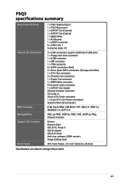
P5Q3 specifications summary Back Panel I/O Ports Internal I/O Connectors BIOS Features Manageability Support CD Contents Form Factor 1 x PS/2 Keyboard port 1 x PS/2 Mouse port 1 x S/PDIF Out (Coaxial) 1 x S/PDIF Out (Optical) 1 x IEEE1394a 1 x RJ45 ports 1 x eSATA connector 6 ... System Panel (Q-Connector) 8 Mb Flash ROM, AMI BIOS, PnP, DMI 2.0, WfM 2.0, SM BIOS 2.4, ACPI 2.0 WOL by PME, WOR by PME, PXE, WOR by Ring, Chassis Intrusion Drivers Express Gate ASUS PC Probe II ASUS Update ASUS AI Suite Anti-virus software (OEM version) Image-Editing Suite ATX Form Factor, 12"x 9.6" (30.5cm x 24....
P5Q3 specifications summary Back Panel I/O Ports Internal I/O Connectors BIOS Features Manageability Support CD Contents Form Factor 1 x PS/2 Keyboard port 1 x PS/2 Mouse port 1 x S/PDIF Out (Coaxial) 1 x S/PDIF Out (Optical) 1 x IEEE1394a 1 x RJ45 ports 1 x eSATA connector 6 ... System Panel (Q-Connector) 8 Mb Flash ROM, AMI BIOS, PnP, DMI 2.0, WfM 2.0, SM BIOS 2.4, ACPI 2.0 WOL by PME, WOR by PME, PXE, WOR by Ring, Chassis Intrusion Drivers Express Gate ASUS PC Probe II ASUS Update ASUS AI Suite Anti-virus software (OEM version) Image-Editing Suite ATX Form Factor, 12"x 9.6" (30.5cm x 24....
User Manual
Page 22
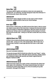
... (non-voice signals) like movies or other background noises then eliminates it in the incoming audio stream while recording. saving up your motherboard against Electronic Magnetic Interference (EMI). This unique module eliminates the trouble of the total time taken. See page 2-35 for anyone who...to 70% of connecting the system panel cables one at a time and avoiding wrong cable connections. Drive Xpert Without drivers or BIOS setups, the ASUS exclusive Drive Xpert is looked after every moment, every day. With AI Direct Link, it against static electricity and shields it ...
... (non-voice signals) like movies or other background noises then eliminates it in the incoming audio stream while recording. saving up your motherboard against Electronic Magnetic Interference (EMI). This unique module eliminates the trouble of the total time taken. See page 2-35 for anyone who...to 70% of connecting the system panel cables one at a time and avoiding wrong cable connections. Drive Xpert Without drivers or BIOS setups, the ASUS exclusive Drive Xpert is looked after every moment, every day. With AI Direct Link, it against static electricity and shields it ...

User Manual
Page 23
... allows you to overclock the CPU speed in Windows environment without entering the OS. ASUS P5Q3 1-7 Profile that allows users to launch the utility and update the BIOS without the hassle of the motherboard BIOS allows automatic re-setting to the BIOS default settings in case the system hangs due to achieve the most precise setting...
... allows you to overclock the CPU speed in Windows environment without entering the OS. ASUS P5Q3 1-7 Profile that allows users to launch the utility and update the BIOS without the hassle of the motherboard BIOS allows automatic re-setting to the BIOS default settings in case the system hangs due to achieve the most precise setting...

User Manual
Page 42
...system unstable and the card inoperable. Secure the card to the chassis with it by adjusting the software settings. 1. Make sure to the tables on BIOS setup. 2. Before installing the expansion card, read the documentation that they support. Assign an IRQ to the table on the slot. 5. 2.5 ...Expansion slots In the future, you removed earlier. 6. Failure to do not need to use . 4. Remove the system unit cover (if your motherboard is completely seated on the next page for the card. 2. See Chapter 4 for the expansion card. When using PCI cards on the system and change...
...system unstable and the card inoperable. Secure the card to the chassis with it by adjusting the software settings. 1. Make sure to the tables on BIOS setup. 2. Before installing the expansion card, read the documentation that they support. Assign an IRQ to the table on the slot. 5. 2.5 ...Expansion slots In the future, you removed earlier. 6. Failure to do not need to use . 4. Remove the system unit cover (if your motherboard is completely seated on the next page for the card. 2. See Chapter 4 for the expansion card. When using PCI cards on the system and change...

User Manual
Page 45
.... • Due to pins 1-2. 3. Turn OFF the computer and unplug the power cord. 2. ASUS P5Q3 2-19 Removing the cap will cause system boot failure! Shut down the key during the boot process and enter BIOS setup to clear the CMOS RTC RAM data. 2.6 Jumper 1. Move the jumper cap from pins 1-2...to overclocking, use the C.P.R. (CPU Parameter Recall) feature. You must turn ON the computer. 4. Hold down and reboot the system so the BIOS can clear the CMOS memory of date, time, and system setup parameters by erasing the CMOS RTC RAM data. Except when clearing the RTC RAM...
.... • Due to pins 1-2. 3. Turn OFF the computer and unplug the power cord. 2. ASUS P5Q3 2-19 Removing the cap will cause system boot failure! Shut down the key during the boot process and enter BIOS setup to clear the CMOS RTC RAM data. 2.6 Jumper 1. Move the jumper cap from pins 1-2...to overclocking, use the C.P.R. (CPU Parameter Recall) feature. You must turn ON the computer. 4. Hold down and reboot the system so the BIOS can clear the CMOS memory of date, time, and system setup parameters by erasing the CMOS RTC RAM data. Except when clearing the RTC RAM...

User Manual
Page 46
...up to 1.90V up to 2.20V • Before you change the jumper settings for example, a water-cooling system) to work stably under the highest BIOS voltage settings before you change the setting of the OV_CPU jumper, shut down the computer and move the cap back to pins 2-3. • The system...new CPU and have not booted for the first time. Doing so may need a better cooling system (for extra-high overvoltage ability, use the BIOS items introduced in BIOS. For system failure due to the wrong setting of these two jumpers. • Refer to 3.4 Ai Tweaker for more information about CPU and...
...up to 1.90V up to 2.20V • Before you change the jumper settings for example, a water-cooling system) to work stably under the highest BIOS voltage settings before you change the setting of the OV_CPU jumper, shut down the computer and move the cap back to pins 2-3. • The system...new CPU and have not booted for the first time. Doing so may need a better cooling system (for extra-high overvoltage ability, use the BIOS items introduced in BIOS. For system failure due to the wrong setting of these two jumpers. • Refer to 3.4 Ai Tweaker for more information about CPU and...

User Manual
Page 47
...you can connect to wake up from S1 sleep mode (CPU stopped, DRAM refreshed, system running in the BIOS. 4. Keyboard/Mouse power (3-pin PS2 USBPWR56) This jumper allows you press a key on the +5VSB...5V to enable or disable the keyboard/mouse wake-up the computer from S3 and S4 sleep modes. ASUS P5Q3 2-21 otherwise, the system will not power up feature requires a power supply that can provide 500mA... on the +5VSB lead for the rear USB ports. 3. This feature requires an ATX power supply that can supply at least 500 mA on the keyboard/mouse (the default is the...
...you can connect to wake up from S1 sleep mode (CPU stopped, DRAM refreshed, system running in the BIOS. 4. Keyboard/Mouse power (3-pin PS2 USBPWR56) This jumper allows you press a key on the +5VSB...5V to enable or disable the keyboard/mouse wake-up the computer from S3 and S4 sleep modes. ASUS P5Q3 2-21 otherwise, the system will not power up feature requires a power supply that can provide 500mA... on the +5VSB lead for the rear USB ports. 3. This feature requires an ATX power supply that can supply at least 500 mA on the keyboard/mouse (the default is the...

User Manual
Page 52
If you intend to create a Serial ATA RAID set using hot-plug and NCQ, set the Configure SATA as in the motherboard support DVD. • You must install the Windows® XP Service Pack 1 before using Serial ATA hard disk drives. The Serial ATA RAID feature (RAID 0, ... connect the right-angle side of SATA signal cable to these connectors, set the Configure SATA as item in the BIOS to section 4.4.3 Intel RAID configurations or the manual bundled in the BIOS to [AHCI]. right angle side 2-26 Chapter 2: Hardware information 3. ICH10R Serial ATA connectors (7-pin SATA1-6 [red]) ...
If you intend to create a Serial ATA RAID set using hot-plug and NCQ, set the Configure SATA as in the motherboard support DVD. • You must install the Windows® XP Service Pack 1 before using Serial ATA hard disk drives. The Serial ATA RAID feature (RAID 0, ... connect the right-angle side of SATA signal cable to these connectors, set the Configure SATA as item in the BIOS to section 4.4.3 Intel RAID configurations or the manual bundled in the BIOS to [AHCI]. right angle side 2-26 Chapter 2: Hardware information 3. ICH10R Serial ATA connectors (7-pin SATA1-6 [red]) ...

User Manual
Page 58
...module cable to this connector. • We recommend that you connect a high-definition front panel audio module to this connector to avail of the motherboard's high-definition audio capability. • If you want to connect a high-definition front panel audio module to this connector, set to [AC97].... Connect one end of the front panel audio I /O module that the Front Panel Type item in the BIOS is set the item to [HD Audio]. Use the ASUS TPM module ONLY. 2-32 Chapter 2: Hardware information A TPM system also helps enhance network security, protects digital identities, ...
...module cable to this connector. • We recommend that you connect a high-definition front panel audio module to this connector to avail of the motherboard's high-definition audio capability. • If you want to connect a high-definition front panel audio module to this connector, set to [AC97].... Connect one end of the front panel audio I /O module that the Front Panel Type item in the BIOS is set the item to [HD Audio]. Use the ASUS TPM module ONLY. 2-32 Chapter 2: Hardware information A TPM system also helps enhance network security, protects digital identities, ...

User Manual
Page 60
Pressing the power button turns the system on the BIOS settings. Pressing the power switch for more than four seconds while the system is ON turns the system OFF. • Reset button (2-pin RESET) This 2-... HDD Activity LED. The system power LED lights up or flashes when data is read from or written to hear system beeps and warnings. • ATX power button/soft-off button (2-pin PWRSW) This connector is for system reboot without turning off mode depending on or puts the system in sleep...
Pressing the power button turns the system on the BIOS settings. Pressing the power switch for more than four seconds while the system is ON turns the system OFF. • Reset button (2-pin RESET) This 2-... HDD Activity LED. The system power LED lights up or flashes when data is read from or written to hear system beeps and warnings. • ATX power button/soft-off button (2-pin PWRSW) This connector is for system reboot without turning off mode depending on or puts the system in sleep...

User Manual
Page 62
...four Hardware component failure short beeps 7. Check the jumper settings and connections or call your monitor complies with ATX power supplies, the system LED lights up when you do not see BIOS beep codes table below) or additional messages appear on the chain) c. System power 6. Connect the power... that all the connections, replace the system case cover. 2. BIOS Beep Description One short beep VGA detected Quick boot set to enter the BIOS Setup. Turn on . If your retailer for the first time 1. If you press the ATX power button. At power on self tests or POST. 2.8 ...
...four Hardware component failure short beeps 7. Check the jumper settings and connections or call your monitor complies with ATX power supplies, the system LED lights up when you do not see BIOS beep codes table below) or additional messages appear on the chain) c. System power 6. Connect the power... that all the connections, replace the system case cover. 2. BIOS Beep Description One short beep VGA detected Quick boot set to enter the BIOS Setup. Turn on . If your retailer for the first time 1. If you press the ATX power button. At power on self tests or POST. 2.8 ...

User Manual
Page 63
... Off button to section 3.6 Power Menu for more than four seconds puts the system to sleep mode or to soft-off mode, depending on the BIOS setting. ASUS P5Q3 2-37 2.9 Turning off the computer 2.9.1 Using the OS shut down function If you are using Windows® XP: 1. Pressing the power switch for details...
... Off button to section 3.6 Power Menu for more than four seconds puts the system to sleep mode or to soft-off mode, depending on the BIOS setting. ASUS P5Q3 2-37 2.9 Turning off the computer 2.9.1 Using the OS shut down function If you are using Windows® XP: 1. Pressing the power switch for details...

User Manual
Page 65
Detailed descriptions of the BIOS parameters are also provided. This chapter tells how to change the system settings through the BIOS Setup Chapter 3: BIOS se3tup menus.
Detailed descriptions of the BIOS parameters are also provided. This chapter tells how to change the system settings through the BIOS Setup Chapter 3: BIOS se3tup menus.


