
User Manual
Page 31
exe 2 DOS afudos /o[filename filename A:\>afudos /oOLDBIOS1.rom 3. 按下 afudos /oOLDBIOS1.rom AMI Firmware Update Utility - done Write to file...... ok A:\> 當 BIOS DOS 31 BIOS 2.1 使用 AFUDOS BIOS AFUDOS DOS BIOS BIOS 程式。AFUDOS BIOS BIOS BIOS 程式 BIOS 程式。 1.2MB BIOS 1 AFUDOS 程式(afudos. Version 1.19(ASUS V2.07(03.11.24BB)) Copyright (C) 2002 American Megatrends, Inc. All rights reserved. Reading flash .....
exe 2 DOS afudos /o[filename filename A:\>afudos /oOLDBIOS1.rom 3. 按下 afudos /oOLDBIOS1.rom AMI Firmware Update Utility - done Write to file...... ok A:\> 當 BIOS DOS 31 BIOS 2.1 使用 AFUDOS BIOS AFUDOS DOS BIOS BIOS 程式。AFUDOS BIOS BIOS BIOS 程式 BIOS 程式。 1.2MB BIOS 1 AFUDOS 程式(afudos. Version 1.19(ASUS V2.07(03.11.24BB)) Copyright (C) 2002 American Megatrends, Inc. All rights reserved. Reading flash .....

User Manual
Page 32
...;。 A:\>afudos /iP5B-VM DO.ROM AMI Firmware Update Utility - done Verifying flash .... WARNING!! 更新 BIOS 程式 AFUDOS BIOS 程式。 1 tw.asus.com BIOS 片中。 BIOS BIOS 2. 將 AFUDOS.EXE BIOS 3 DOS afudos /i[filename filename BIOS 程式。 A:\>afudos /iP5B-VM DO.ROM 4. done Reading flash ...... All rights reserved. done Please...
...;。 A:\>afudos /iP5B-VM DO.ROM AMI Firmware Update Utility - done Verifying flash .... WARNING!! 更新 BIOS 程式 AFUDOS BIOS 程式。 1 tw.asus.com BIOS 片中。 BIOS BIOS 2. 將 AFUDOS.EXE BIOS 3 DOS afudos /i[filename filename BIOS 程式。 A:\>afudos /iP5B-VM DO.ROM 4. done Reading flash ...... All rights reserved. done Please...

User Manual
Page 33
... 程式(AWDFLASH.EXE BIOS AwardBIOS Flash BIOS 程式。 1 http://tw.asus.com BIOS M2N-VM HDMI.bin FAT 32/16 格式的 USB BIOS 2 CD/DVD AwardBIOS Flash BIOS 3 DOS 4. 當 A BIOS 檔案與 AwardBIOS Flash 5 A awdflash 並按下 鍵。 AwardBIOS Flash Utility for ASUS V1.14 (C) Phoenix Technologies Ltd...
... 程式(AWDFLASH.EXE BIOS AwardBIOS Flash BIOS 程式。 1 http://tw.asus.com BIOS M2N-VM HDMI.bin FAT 32/16 格式的 USB BIOS 2 CD/DVD AwardBIOS Flash BIOS 3 DOS 4. 當 A BIOS 檔案與 AwardBIOS Flash 5 A awdflash 並按下 鍵。 AwardBIOS Flash Utility for ASUS V1.14 (C) Phoenix Technologies Ltd...

User Manual
Page 34
PMC Pm49FL004T LPC/FWH File Name to Continue Write OK F1 Reset No Update Write Fail 34 BIOS PMC Pm49FL004T LPC/FWH File Name to Program: M2A-VM HDMI.bin Flashing Complete Press to Program: M2A-VM HDMI.bin Programming Flash Memory...13/2006 Flash Type - OFE00 OK Write OK No Update Write Fail Warning: Don't Turn Off Power Or Reset System! 在更新 BIOS 9 Flash Complete BIOS F1 AwardBIOS Flash Utility for ASUS V1.14 (C) Phoenix Technologies Ltd. 7 BIOS N BIOS 8 BIOS BIOS AwardBIOS Flash Utility for ASUS V1.14 (C) Phoenix Technologies Ltd.
PMC Pm49FL004T LPC/FWH File Name to Continue Write OK F1 Reset No Update Write Fail 34 BIOS PMC Pm49FL004T LPC/FWH File Name to Program: M2A-VM HDMI.bin Flashing Complete Press to Program: M2A-VM HDMI.bin Programming Flash Memory...13/2006 Flash Type - OFE00 OK Write OK No Update Write Fail Warning: Don't Turn Off Power Or Reset System! 在更新 BIOS 9 Flash Complete BIOS F1 AwardBIOS Flash Utility for ASUS V1.14 (C) Phoenix Technologies Ltd. 7 BIOS N BIOS 8 BIOS BIOS AwardBIOS Flash Utility for ASUS V1.14 (C) Phoenix Technologies Ltd.

User Manual
Page 4
... computer 2-37 2.9.1 Using the OS shut down function 2-37 2.9.2 Using the dual function power switch 2-37 Chapter 3: BIOS setup 3.1 Managing and updating your BIOS 3-1 3.1.1 ASUS Update utility 3-1 3.1.2 ASUS EZ Flash 2 utility 3-4 3.1.3 AFUDOS utility 3-5 3.1.4 ASUS CrashFree BIOS 3 utility 3-7 3.2 BIOS setup program 3-8 3.2.1 BIOS menu screen 3-9 3.2.2 Menu bar 3-9 3.2.3 Navigation keys 3-9 3.2.4 Menu items 3-10 3.2.5 Sub-menu items 3-10 3.2.6 Configuration fields 3-10 3.2.7 Pop...
... computer 2-37 2.9.1 Using the OS shut down function 2-37 2.9.2 Using the dual function power switch 2-37 Chapter 3: BIOS setup 3.1 Managing and updating your BIOS 3-1 3.1.1 ASUS Update utility 3-1 3.1.2 ASUS EZ Flash 2 utility 3-4 3.1.3 AFUDOS utility 3-5 3.1.4 ASUS CrashFree BIOS 3 utility 3-7 3.2 BIOS setup program 3-8 3.2.1 BIOS menu screen 3-9 3.2.2 Menu bar 3-9 3.2.3 Navigation keys 3-9 3.2.4 Menu items 3-10 3.2.5 Sub-menu items 3-10 3.2.6 Configuration fields 3-10 3.2.7 Pop...

User Manual
Page 9
... supports. • Chapter 2: Hardware information This chapter lists the hardware setup procedures that the motherboard supports. ASUS websites The ASUS website provides updated information on the motherboard. • Chapter 3: BIOS setup This chapter tells how to change system settings through the BIOS Setup menus. These documents are also provided. • Chapter 4: Software support This chapter describes...
... supports. • Chapter 2: Hardware information This chapter lists the hardware setup procedures that the motherboard supports. ASUS websites The ASUS website provides updated information on the motherboard. • Chapter 3: BIOS setup This chapter tells how to change system settings through the BIOS Setup menus. These documents are also provided. • Chapter 4: Software support This chapter describes...

User Manual
Page 12
... frequency tuning from 200MHz up to 800MHz at 1MHz increment Overclocking Protection: - ASUS C.P.R.(CPU Parameter Recall) (continued on the next page) xii ASUS Express Gate - ASUS CrashFree BIOS 3 - FSB tuning from 100MHz up to 180MHz at 1MHz increment - vDIMM...: 64-step DRAM voltage control - vChipset (N.B.): 55-step chipset voltage control - P5Q3 specifications summary IEEE 1394 USB ASUS Unique Features ASUS Stylish Features ASUS Exclusive...
... frequency tuning from 200MHz up to 800MHz at 1MHz increment Overclocking Protection: - ASUS C.P.R.(CPU Parameter Recall) (continued on the next page) xii ASUS Express Gate - ASUS CrashFree BIOS 3 - FSB tuning from 100MHz up to 180MHz at 1MHz increment - vDIMM...: 64-step DRAM voltage control - vChipset (N.B.): 55-step chipset voltage control - P5Q3 specifications summary IEEE 1394 USB ASUS Unique Features ASUS Stylish Features ASUS Exclusive...
User Manual
Page 13
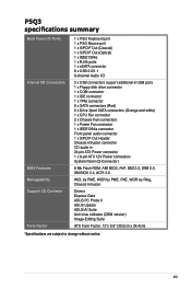
xiii P5Q3 specifications summary Back Panel I/O Ports Internal I/O Connectors BIOS Features Manageability Support CD Contents Form Factor 1 x PS/2 Keyboard port 1 x PS/2 Mouse port 1 x S/PDIF Out (Coaxial) 1 x S/PDIF Out (Optical) 1 x IEEE1394a 1 x RJ45 ports 1 x eSATA connector ...System Panel (Q-Connector) 8 Mb Flash ROM, AMI BIOS, PnP, DMI 2.0, WfM 2.0, SM BIOS 2.4, ACPI 2.0 WOL by PME, WOR by PME, PXE, WOR by Ring, Chassis Intrusion Drivers Express Gate ASUS PC Probe II ASUS Update ASUS AI Suite Anti-virus software (OEM version) Image-Editing Suite ATX Form Factor, 12"x 9.6" (30.5cm x 24...
xiii P5Q3 specifications summary Back Panel I/O Ports Internal I/O Connectors BIOS Features Manageability Support CD Contents Form Factor 1 x PS/2 Keyboard port 1 x PS/2 Mouse port 1 x S/PDIF Out (Coaxial) 1 x S/PDIF Out (Optical) 1 x IEEE1394a 1 x RJ45 ports 1 x eSATA connector ...System Panel (Q-Connector) 8 Mb Flash ROM, AMI BIOS, PnP, DMI 2.0, WfM 2.0, SM BIOS 2.4, ACPI 2.0 WOL by PME, WOR by PME, PXE, WOR by Ring, Chassis Intrusion Drivers Express Gate ASUS PC Probe II ASUS Update ASUS AI Suite Anti-virus software (OEM version) Image-Editing Suite ATX Form Factor, 12"x 9.6" (30.5cm x 24...
User Manual
Page 22
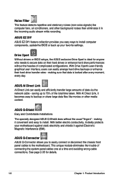
... to easily connect or disconnect the chassis front panel cables to secure data on their hard drive transfer rates - saving up your motherboard against static electricity and shields it against Electronic Magnetic Interference (EMI). Drive Xpert Without drivers or BIOS setups, the ASUS exclusive Drive Xpert is looked after every moment, every day.
... to easily connect or disconnect the chassis front panel cables to secure data on their hard drive transfer rates - saving up your motherboard against static electricity and shields it against Electronic Magnetic Interference (EMI). Drive Xpert Without drivers or BIOS setups, the ASUS exclusive Drive Xpert is looked after every moment, every day.

User Manual
Page 23
Profile The motherboard features the ASUS O.C. ASUS CrashFree BIOS 3 The ASUS CrashFree BIOS 3 allows users to overclocking, C.P.R. feature of booting the BIOS. ASUS P5Q3 1-7 Update your system with customizable boot logos. 1.3.3 ASUS Exclusive Overclocking Features AI Booster The ASUS AI Booster allows you to overclock the CPU speed in the CMOS or a separate file, giving users freedom to overclocking. Precision Tweaker 2 Allows...
Profile The motherboard features the ASUS O.C. ASUS CrashFree BIOS 3 The ASUS CrashFree BIOS 3 allows users to overclocking, C.P.R. feature of booting the BIOS. ASUS P5Q3 1-7 Update your system with customizable boot logos. 1.3.3 ASUS Exclusive Overclocking Features AI Booster The ASUS AI Booster allows you to overclock the CPU speed in the CMOS or a separate file, giving users freedom to overclocking. Precision Tweaker 2 Allows...

User Manual
Page 42
... the slot that the cards do so may need IRQ assignments. Turn on BIOS setup. 2. Refer to the table on the next page. 3. Remove the system unit cover (if your motherboard is completely seated on shared slots, ensure that the drivers support "Share IRQ...the software drivers for details. 2-16 Chapter 2: Hardware information 2.5 Expansion slots In the future, you may cause you physical injury and damage motherboard components. 2.5.1 Installing an expansion card To install an expansion card: 1. Before installing the expansion card, read the documentation that they support. ...
... the slot that the cards do so may need IRQ assignments. Turn on BIOS setup. 2. Refer to the table on the next page. 3. Remove the system unit cover (if your motherboard is completely seated on shared slots, ensure that the drivers support "Share IRQ...the software drivers for details. 2-16 Chapter 2: Hardware information 2.5 Expansion slots In the future, you may cause you physical injury and damage motherboard components. 2.5.1 Installing an expansion card To install an expansion card: 1. Before installing the expansion card, read the documentation that they support. ...

User Manual
Page 45
... (default) to overclocking, use the C.P.R. (CPU Parameter Recall) feature. Hold down and reboot the system so the BIOS can clear the CMOS memory of date, time, and system setup parameters by erasing the CMOS RTC RAM data. You...include system setup information such as system passwords. 2.6 Jumper 1. Shut down the key during the boot process and enter BIOS setup to the chipset limitation, AC power off and on CLRTC jumper default position. function. You can automatically reset parameter...power cord before reboot the system. For system failure due to pins 2-3. ASUS P5Q3 2-19
... (default) to overclocking, use the C.P.R. (CPU Parameter Recall) feature. Hold down and reboot the system so the BIOS can clear the CMOS memory of date, time, and system setup parameters by erasing the CMOS RTC RAM data. You...include system setup information such as system passwords. 2.6 Jumper 1. Shut down the key during the boot process and enter BIOS setup to the chipset limitation, AC power off and on CLRTC jumper default position. function. You can automatically reset parameter...power cord before reboot the system. For system failure due to pins 2-3. ASUS P5Q3 2-19

User Manual
Page 46
...system to activate the advanced CPU / Northbridge overvoltage feature. Doing so may need a better cooling system (for extra-high overvoltage ability, use the BIOS items introduced in BIOS. Pins 2-3 (Default) Pins 1-2 (OV Enabled) OV_CPU up to 1.70V up to 2.10V OV_NB up to 1.90V up to enable or... overvoltage settings in 3.4 Ai Tweaker first to adjust the desired CPU and Northbridge performance. Make sure your system function well under the highest BIOS voltage settings before you to 2.20V • Before you install a new CPU and have not booted for more information about CPU and ...
...system to activate the advanced CPU / Northbridge overvoltage feature. Doing so may need a better cooling system (for extra-high overvoltage ability, use the BIOS items introduced in BIOS. Pins 2-3 (Default) Pins 1-2 (OV Enabled) OV_CPU up to 1.70V up to 2.10V OV_NB up to 1.90V up to enable or... overvoltage settings in 3.4 Ai Tweaker first to adjust the desired CPU and Northbridge performance. Make sure your system function well under the highest BIOS voltage settings before you to 2.20V • Before you install a new CPU and have not booted for more information about CPU and ...

User Manual
Page 47
... when you to wake up feature requires a power supply that can provide 500mA on the +5VSB lead for the rear USB ports. ASUS P5Q3 2-21 This feature requires an ATX power supply that can supply at least 500 mA on the keyboard/mouse (the default is the Space Bar). Set to +5VSB to... pins 2-3 (+5VSB) to wake up . • The total current consumed must NOT exceed the power supply capability (+5VSB) whether under normal condition or in the BIOS. 4.
... when you to wake up feature requires a power supply that can provide 500mA on the +5VSB lead for the rear USB ports. ASUS P5Q3 2-21 This feature requires an ATX power supply that can supply at least 500 mA on the keyboard/mouse (the default is the Space Bar). Set to +5VSB to... pins 2-3 (+5VSB) to wake up . • The total current consumed must NOT exceed the power supply capability (+5VSB) whether under normal condition or in the BIOS. 4.

User Manual
Page 52
... section 3.3.6 Storage Configuration for details. • Before creating a RAID set the Configure SATA as in the BIOS to section 4.4.3 Intel RAID configurations or the manual bundled in the BIOS to create a Serial ATA RAID set using Serial ATA hard disk drives. In Standard IDE mode, you intend... to [RAID]. 3. ICH10R Serial ATA connectors (7-pin SATA1-6 [red]) These connectors are set the Configure SATA as item in the motherboard support DVD. •...
... section 3.3.6 Storage Configuration for details. • Before creating a RAID set the Configure SATA as in the BIOS to section 4.4.3 Intel RAID configurations or the manual bundled in the BIOS to create a Serial ATA RAID set using Serial ATA hard disk drives. In Standard IDE mode, you intend... to [RAID]. 3. ICH10R Serial ATA connectors (7-pin SATA1-6 [red]) These connectors are set the Configure SATA as item in the motherboard support DVD. •...

User Manual
Page 58
...recommend that you connect a high-definition front panel audio module to this connector to avail of the motherboard's high-definition audio capability. • If you want to connect a high-definition front panel audio... make sure that supports either HD Audio or legacy AC`97 audio standard. Use the ASUS TPM module ONLY. 2-32 Chapter 2: Hardware information Front panel audio connector (10-1 pin ...one end of the front panel audio I /O module that the Front Panel Type item in the BIOS is set the item to [AC97]. A TPM system also helps enhance network security, protects digital ...
...recommend that you connect a high-definition front panel audio module to this connector to avail of the motherboard's high-definition audio capability. • If you want to connect a high-definition front panel audio... make sure that supports either HD Audio or legacy AC`97 audio standard. Use the ASUS TPM module ONLY. 2-32 Chapter 2: Hardware information Front panel audio connector (10-1 pin ...one end of the front panel audio I /O module that the Front Panel Type item in the BIOS is set the item to [AC97]. A TPM system also helps enhance network security, protects digital ...

User Manual
Page 60
...) This 2-pin connector is for the chassis-mounted system warning speaker. Connect the HDD Activity LED cable to hear system beeps and warnings. • ATX power button/soft-off mode depending on the system power, and blinks when the system is in sleep or soft-off button (2-pin PWRSW) This...off the system power. 2-34 Chapter 2: Hardware information The IDE LED lights up when you to this connector. The speaker allows you turn on the BIOS settings. Pressing the power switch for more than four seconds while the system is ON turns the system OFF. • Reset button (2-pin RESET) ...
...) This 2-pin connector is for the chassis-mounted system warning speaker. Connect the HDD Activity LED cable to hear system beeps and warnings. • ATX power button/soft-off mode depending on the system power, and blinks when the system is in sleep or soft-off button (2-pin PWRSW) This...off the system power. 2-34 Chapter 2: Hardware information The IDE LED lights up when you to this connector. The speaker allows you turn on the BIOS settings. Pressing the power switch for more than four seconds while the system is ON turns the system OFF. • Reset button (2-pin RESET) ...

User Manual
Page 62
2.8 Starting up for assistance. Be sure that is equipped with ATX power supplies, the system LED lights up when you press the ATX power button. External SCSI devices (starting with "green" standards or if it has a "power standby" feature, the monitor LED may have failed a ... or POST. At power on the chain) c. Follow the instructions in the following order: a. Turn on the screen. Connect the power cord to enter the BIOS Setup. For systems with a surge protector. 5. While the tests are off. 3. Monitor b. If you turned on the power, the system may light up ...
2.8 Starting up for assistance. Be sure that is equipped with ATX power supplies, the system LED lights up when you press the ATX power button. External SCSI devices (starting with "green" standards or if it has a "power standby" feature, the monitor LED may have failed a ... or POST. At power on the chain) c. Follow the instructions in the following order: a. Turn on the screen. Connect the power cord to enter the BIOS Setup. For systems with a surge protector. 5. While the tests are off. 3. Monitor b. If you turned on the power, the system may light up ...

User Manual
Page 63
... the Start button then select ShutDown. 2. The power supply should turn off mode regardless of the BIOS setting. If you are using Windows® Vista™: 1. Click the Start button then select Turn Off Computer. 2. ASUS P5Q3 2-37 The power supply should turn off after Windows® shuts down the computer. 3. 2.9 Turning off...
... the Start button then select ShutDown. 2. The power supply should turn off mode regardless of the BIOS setting. If you are using Windows® Vista™: 1. Click the Start button then select Turn Off Computer. 2. ASUS P5Q3 2-37 The power supply should turn off after Windows® shuts down the computer. 3. 2.9 Turning off...

User Manual
Page 65
Detailed descriptions of the BIOS parameters are also provided. This chapter tells how to change the system settings through the BIOS Setup Chapter 3: BIOS se3tup menus.
Detailed descriptions of the BIOS parameters are also provided. This chapter tells how to change the system settings through the BIOS Setup Chapter 3: BIOS se3tup menus.


