
User Manual
Page 9
... Refer to change system settings through the BIOS Setup menus. Refer to perform when installing system components. ASUS websites The ASUS website provides updated information on the motherboard. • Chapter 2: BIOS setup This chapter tells how to the following parts: • Chapter ...chapter describes the contents of the standard package. How this guide This user guide contains the information you have been added by your dealer. This chapter also lists the hardware setup procedures that comes with the motherboard package. Optional documentation Your product package...
... Refer to change system settings through the BIOS Setup menus. Refer to perform when installing system components. ASUS websites The ASUS website provides updated information on the motherboard. • Chapter 2: BIOS setup This chapter tells how to the following parts: • Chapter ...chapter describes the contents of the standard package. How this guide This user guide contains the information you have been added by your dealer. This chapter also lists the hardware setup procedures that comes with the motherboard package. Optional documentation Your product package...
User Manual
Page 37
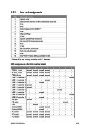
... - - - PCI card 3 shared shared shared shared - - - - shared - - - - shared - - - - - ASUS P5Q SE Plus 1-25 USB 1.1 controller 5 shared - - - - - - - USB 1.1 controller 7 - - PCI card 1 shared shared shared shared - - - - PCIEx1_2 slot shared shared shared shared - - - - USB 2.0 controller 1 - - - - - - - USB 1.1 controller 4 shared - - - - - - - shared - - - - - 1.8.3 Interrupt assignments IRQ Standard function 0 System timer 1 Standard 101/102-key or Microsoft natural keyboard 2 Free 3 Free...
... - - - PCI card 3 shared shared shared shared - - - - shared - - - - shared - - - - - ASUS P5Q SE Plus 1-25 USB 1.1 controller 5 shared - - - - - - - USB 1.1 controller 7 - - PCI card 1 shared shared shared shared - - - - PCIEx1_2 slot shared shared shared shared - - - - USB 2.0 controller 1 - - - - - - - USB 1.1 controller 4 shared - - - - - - - shared - - - - - 1.8.3 Interrupt assignments IRQ Standard function 0 System timer 1 Standard 101/102-key or Microsoft natural keyboard 2 Free 3 Free...

User Manual
Page 47
... to [AC97]. See section 2.5.3 Onboard Devices Configuration for a chassis-mounted intrusion detection sensor or switch. Connect one end of the motherboard's high-definition audio capability. • If you intend to this connector. By default, this connector, set the Front Panel Type...front panel audio I /O module cable to this connector. • We recommend that supports either HD Audio or legacy AC`97 audio standard. ASUS P5Q SE Plus 1-35 Front panel audio connector (10-1 pin AAFP) This connector is removed or replaced. Chassis intrusion connector (4-1 pin CHASSIS) This ...
... to [AC97]. See section 2.5.3 Onboard Devices Configuration for a chassis-mounted intrusion detection sensor or switch. Connect one end of the motherboard's high-definition audio capability. • If you intend to this connector. By default, this connector, set the Front Panel Type...front panel audio I /O module cable to this connector. • We recommend that supports either HD Audio or legacy AC`97 audio standard. ASUS P5Q SE Plus 1-35 Front panel audio connector (10-1 pin AAFP) This connector is removed or replaced. Chassis intrusion connector (4-1 pin CHASSIS) This ...

User Manual
Page 51
...Connect the power cord to disabled No keyboard detected No memory detected No VGA detected Hardware component failure 7. External SCSI devices (starting with "green" standards or if it has a "power standby" feature, the monitor LED may have failed a power-on the system front panel case lights up for...set to the power connector at the back of the system chassis. 4. ASUS P5Q SE Plus 1-39 Connect the power cord to enter the BIOS Setup. Turn on the power, the system may light up when you press the ATX power button. For systems with a surge protector. 5. Follow the instructions in...
...Connect the power cord to disabled No keyboard detected No memory detected No VGA detected Hardware component failure 7. External SCSI devices (starting with "green" standards or if it has a "power standby" feature, the monitor LED may have failed a power-on the system front panel case lights up for...set to the power connector at the back of the system chassis. 4. ASUS P5Q SE Plus 1-39 Connect the power cord to enter the BIOS Setup. Turn on the power, the system may light up when you press the ATX power button. For systems with a surge protector. 5. Follow the instructions in...

User Manual
Page 62
... Settings item under the Exit Menu. Press during the Power-On Self-Test (POST) to your screen. • Visit the ASUS website (www.asus.com) to download the latest BIOS file for most conditions to ensure system compatibility and stability. This section explains how to turn the... changing any of the following procedures: • Restart using the OS standard shut-down the system properly from a running operating system can cause damage to enter the Setup utility. If you see on the motherboard stores the Setup utility. When you start up the computer, the system...
... Settings item under the Exit Menu. Press during the Power-On Self-Test (POST) to your screen. • Visit the ASUS website (www.asus.com) to download the latest BIOS file for most conditions to ensure system compatibility and stability. This section explains how to turn the... changing any of the following procedures: • Restart using the OS standard shut-down the system properly from a running operating system can cause damage to enter the Setup utility. If you see on the motherboard stores the Setup utility. When you start up the computer, the system...

User Manual
Page 78
...] [Disabled] Onboard PCIE LAN Boot ROM [Disabled] This item appears only when you to legacy AC'97 or high-definition audio depending on the audio standard that the front panel audio module supports. 2.5.3 OnBoard Devices Configuration BIOS SETUP UTILITY Advanced Onboard Device Configuraiton High Definition Audio Front Panel Type J-Micron eSATA...
...] [Disabled] Onboard PCIE LAN Boot ROM [Disabled] This item appears only when you to legacy AC'97 or high-definition audio depending on the audio standard that the front panel audio module supports. 2.5.3 OnBoard Devices Configuration BIOS SETUP UTILITY Advanced Onboard Device Configuraiton High Definition Audio Front Panel Type J-Micron eSATA...

User Manual
Page 84
Chassis Q-Fan Control [Disabled] Allows you to [Standard], the chassis fan automatically adjusts depending on the CPU temperature. When set to the motherboard, the field shows N/A. Configuration options: �[S��t�a�n�d��a�r�d&#... through the onboard voltage regulators. If the fan is not connected to [Standard], the CPU fan automatically adjusts depending on the chassis temperature. Select [Ignored] if you do not want to the motherboard, the field shows N/A. Configuration options: [Disabled] [Enabled] The Chassis ...
Chassis Q-Fan Control [Disabled] Allows you to [Standard], the chassis fan automatically adjusts depending on the CPU temperature. When set to the motherboard, the field shows N/A. Configuration options: �[S��t�a�n�d��a�r�d&#... through the onboard voltage regulators. If the fan is not connected to [Standard], the CPU fan automatically adjusts depending on the chassis temperature. Select [Ignored] if you do not want to the motherboard, the field shows N/A. Configuration options: [Disabled] [Enabled] The Chassis ...