
User Manual
Page 29
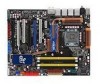
2.2.2 Layout contents Connectors/Jumpers/Slots 1. ATX power connectors (24-pin EATXPWR, 8-pin ATX12V) 2. ICH10R Serial ATA connectors [red] (7-pin SATA1-6) 11. Clear RTC RAM (3-pin CLRTC) 16. Optical drive audio connector (4-pin CD) 19. ASUS Express Gate SSD Page 2-37 2-6 2-34 2-11 2-24 2-35 2-35... 2-28 2-29 2-30 2-31 2-39 2-25 2-28 2-23 2-32 2-33 2-38 2-36 2-38 4-43 ASUS P5Q Premium 2-3 USB connectors (10...
2.2.2 Layout contents Connectors/Jumpers/Slots 1. ATX power connectors (24-pin EATXPWR, 8-pin ATX12V) 2. ICH10R Serial ATA connectors [red] (7-pin SATA1-6) 11. Clear RTC RAM (3-pin CLRTC) 16. Optical drive audio connector (4-pin CD) 19. ASUS Express Gate SSD Page 2-37 2-6 2-34 2-11 2-24 2-35 2-35... 2-28 2-29 2-30 2-31 2-39 2-25 2-28 2-23 2-32 2-33 2-38 2-36 2-38 4-43 ASUS P5Q Premium 2-3 USB connectors (10...

User Manual
Page 49
... to the chipset behavior, AC power off and on CLRTC jumper default position. The onboard button cell battery powers the RAM data in CMOS. To erase the RTC RAM 1. Move the jumper cap from pins 1-2 (default) to enable C.P.R. Plug the power cord and turn off is ... 5-10 seconds, then move the jumper again to clear the Real Time Clock (RTC) RAM in CMOS, which include system setup information such as system passwords. For system failure due to pins 1-2. 3. function. ASUS P5Q Premium 2-23 2.6 Jumpers 1. After the CMOS clearance, reinstall the battery. • You do...
... to the chipset behavior, AC power off and on CLRTC jumper default position. The onboard button cell battery powers the RAM data in CMOS. To erase the RTC RAM 1. Move the jumper cap from pins 1-2 (default) to enable C.P.R. Plug the power cord and turn off is ... 5-10 seconds, then move the jumper again to clear the Real Time Clock (RTC) RAM in CMOS, which include system setup information such as system passwords. For system failure due to pins 1-2. 3. function. ASUS P5Q Premium 2-23 2.6 Jumpers 1. After the CMOS clearance, reinstall the battery. • You do...

User Manual
Page 80
...firmware chip that the computer can recognize these changes and record them in the CMOS RAM of your BIOS. The firmware chip on your screen. • Visit the ASUS website (www.asus.com) to run this motherboard. 3-8 Chapter 3: BIOS setup Use the BIOS Setup program when you are for ...this program. This requires you see on the motherboard stores the Setup utility. Press during the Power-On Self-...
...firmware chip that the computer can recognize these changes and record them in the CMOS RAM of your BIOS. The firmware chip on your screen. • Visit the ASUS website (www.asus.com) to run this motherboard. 3-8 Chapter 3: BIOS setup Use the BIOS Setup program when you are for ...this program. This requires you see on the motherboard stores the Setup utility. Press during the Power-On Self-...

User Manual
Page 109
...for information on top of at least six letters and/or numbers, then press . 3. Select an item then press to erase the RTC RAM. From the password box, type a password composed of the screen shows the default Not Installed. Confirm the password when prompted. The message... Change User Password to disabled password. The Supervisor Password item on how to display the configuration options. If you forget your password. ASUS P5Q Premium 3-37 Change Supervisor Password Select this item shows Installed. To change the supervisor password, follow the same steps as in setting a user...
...for information on top of at least six letters and/or numbers, then press . 3. Select an item then press to erase the RTC RAM. From the password box, type a password composed of the screen shows the default Not Installed. Confirm the password when prompted. The message... Change User Password to disabled password. The Supervisor Password item on how to display the configuration options. If you forget your password. ASUS P5Q Premium 3-37 Change Supervisor Password Select this item shows Installed. To change the supervisor password, follow the same steps as in setting a user...

User Manual
Page 116
... message asking if you want to save the changes that you made changes to fields other changes before saving the values to the non-volatile RAM. 3-44 Chapter 3: BIOS setup Discard Changes This option allows you to Sub Screen F1 General Help F10 Save and Exit ESC Exit v02.... & Save Changes Exit & Discard Changes Discard Changes Load Setup Defaults Exit system setup after saving the changes. An onboard backup battery sustains the CMOS RAM so it stays on the Setup menus. When you select this option, a confirmation appears. Press to save changes and exit. 3.9 Exit menu The...
... message asking if you want to save the changes that you made changes to fields other changes before saving the values to the non-volatile RAM. 3-44 Chapter 3: BIOS setup Discard Changes This option allows you to Sub Screen F1 General Help F10 Save and Exit ESC Exit v02.... & Save Changes Exit & Discard Changes Discard Changes Load Setup Defaults Exit system setup after saving the changes. An onboard backup battery sustains the CMOS RAM so it stays on the Setup menus. When you select this option, a confirmation appears. Press to save changes and exit. 3.9 Exit menu The...


