User Manual
Page 25
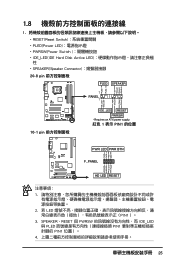
1.8 1 RESET(Reset Switch PLED(Power LED PWRSW(Power Switch IDE_LED(IDE Hard Disk Active LED SPEAKER(Speaker Connector 20-8 pin PLED SPEAKER 1 PANEL1 PLED+ PLED+5V Ground Ground Speaker P5B-E ® IDE_LED+ IDE_LED- PWR Ground Reset Ground 10-1 pin IDE_LED RESET PWRSW * Requires an ATX power supply. 紅色 1 表示 PIN1 的位置 PLED+ PLEDPWR GND...
1.8 1 RESET(Reset Switch PLED(Power LED PWRSW(Power Switch IDE_LED(IDE Hard Disk Active LED SPEAKER(Speaker Connector 20-8 pin PLED SPEAKER 1 PANEL1 PLED+ PLED+5V Ground Ground Speaker P5B-E ® IDE_LED+ IDE_LED- PWR Ground Reset Ground 10-1 pin IDE_LED RESET PWRSW * Requires an ATX power supply. 紅色 1 表示 PIN1 的位置 PLED+ PLEDPWR GND...

User Manual
Page 13
P5Q PRO Turbo specifications summary Internal I/O Connectors BIOS Features Manageability Support DVD Contents Form Factor 3 x USB connectors support additional 6 USB ports 1 x IDE connector 1 x COM connector 5 x SATA connectors 2 x Drive Xpert SATA connectors (Orange and White) 1 x CPU Fan connector 2 x Chassis Fan connectors 1 x Power Fan connector 1 x IEEE1394a connector Front panel audio connector 1 x S/PDIF Out Header Chassis Intrusion connector CD audio in 24-pin ATX Power connector 8-pin EATX 12V Power connectors System Panel (Q-Connector) 8 Mb AMI BIOS, PnP...
P5Q PRO Turbo specifications summary Internal I/O Connectors BIOS Features Manageability Support DVD Contents Form Factor 3 x USB connectors support additional 6 USB ports 1 x IDE connector 1 x COM connector 5 x SATA connectors 2 x Drive Xpert SATA connectors (Orange and White) 1 x CPU Fan connector 2 x Chassis Fan connectors 1 x Power Fan connector 1 x IEEE1394a connector Front panel audio connector 1 x S/PDIF Out Header Chassis Intrusion connector CD audio in 24-pin ATX Power connector 8-pin EATX 12V Power connectors System Panel (Q-Connector) 8 Mb AMI BIOS, PnP...

User Manual
Page 44
...Chapter 2 • The USB device wake-up from S1 sleep mode (CPU stopped, DRAM refreshed, system running in low power mode) using the connected USB devices. This feature requires an ATX power supply that can provide 500mA on the +5VSB lead, and a corresponding setting in sleep mode. 2-24 Chapter 2: Hardware ... S4 sleep modes. USB device wake-up (3-pin USBPW1-4, USBPW7-10, USBPW1112) Set these jumpers to +5V to wake up feature requires a power supply that you press a key on the keyboard/mouse (the default is for the internal USB connectors that can supply at least 500 mA on the...
...Chapter 2 • The USB device wake-up from S1 sleep mode (CPU stopped, DRAM refreshed, system running in low power mode) using the connected USB devices. This feature requires an ATX power supply that can provide 500mA on the +5VSB lead, and a corresponding setting in sleep mode. 2-24 Chapter 2: Hardware ... S4 sleep modes. USB device wake-up (3-pin USBPW1-4, USBPW7-10, USBPW1112) Set these jumpers to +5V to wake up feature requires a power supply that you press a key on the keyboard/mouse (the default is for the internal USB connectors that can supply at least 500 mA on the...

User Manual
Page 56
...2 connectors support the ASUS Q FAN 2 feature. • If you install two VGA cards, we recommend that the black wire of each cable matches the ground pin of 1 A~7 A (84 W max.) at +12V. These are not jumpers! Do not place jumper caps on the motherboard, making...flow inside the system may damage the motherboard components. Do not forget to connect the fan cables to the motherboard connector labeled CHA_FAN1 or CHA_FAN2 for better thermal environment. CPU, chassis, and power fan connectors (4-pin CPU_FAN; 3-pin CHA_FAN1-2; 3-pin PWR_FAN) The fan connectors support cooling fans of 350 mA~...
...2 connectors support the ASUS Q FAN 2 feature. • If you install two VGA cards, we recommend that the black wire of each cable matches the ground pin of 1 A~7 A (84 W max.) at +12V. These are not jumpers! Do not place jumper caps on the motherboard, making...flow inside the system may damage the motherboard components. Do not forget to connect the fan cables to the motherboard connector labeled CHA_FAN1 or CHA_FAN2 for better thermal environment. CPU, chassis, and power fan connectors (4-pin CPU_FAN; 3-pin CHA_FAN1-2; 3-pin PWR_FAN) The fan connectors support cooling fans of 350 mA~...

User Manual
Page 57
.... Chapter 2 ASUS P5Q PRO Turbo 2-37 asus.com/PowerSupplyCalculator/PSCalculator.aspx?SLanguage=en-us for your system, refer to the Recommended Power Supply Wattage Calculator at http://support. Otherwise, the system will not boot. • We recommend that complies with more power-consuming devices. 12. ATX power connectors (24-pin EATXPWR; 8-pin EATX12V) These connectors are designed to connect the 8-pin EATX +12 V power plug.
.... Chapter 2 ASUS P5Q PRO Turbo 2-37 asus.com/PowerSupplyCalculator/PSCalculator.aspx?SLanguage=en-us for your system, refer to the Recommended Power Supply Wattage Calculator at http://support. Otherwise, the system will not boot. • We recommend that complies with more power-consuming devices. 12. ATX power connectors (24-pin EATXPWR; 8-pin EATX12V) These connectors are designed to connect the 8-pin EATX +12 V power plug.

User Manual
Page 58
... is read from or written to this connector. 13. Connect the chassis power LED cable to the HDD. • System warning speaker (4-pin SPEAKER) This 4-pin connector is for the HDD Activity LED. Pressing the power switch for more than four seconds while ... LED (2-pin IDE_LED) This 2-pin connector is for the chassis-mounted system warning speaker. System panel connector (20-8 pin PANEL) This connector supports several chassis-mounted functions. Connect the HDD Activity LED cable to hear system beeps and warnings. • ATX power button/soft-off the system power. 2-38...
... is read from or written to this connector. 13. Connect the chassis power LED cable to the HDD. • System warning speaker (4-pin SPEAKER) This 4-pin connector is for the HDD Activity LED. Pressing the power switch for more than four seconds while ... LED (2-pin IDE_LED) This 2-pin connector is for the chassis-mounted system warning speaker. System panel connector (20-8 pin PANEL) This connector supports several chassis-mounted functions. Connect the HDD Activity LED cable to hear system beeps and warnings. • ATX power button/soft-off the system power. 2-38...

User Manual
Page 59
... sure the orientation matches the labels on the Q-Connector to know the detailed pin definitions, and then match them to install the ASUS Q-Connector. 1. Refer to the labels on the motherboard. 3. The front panel functions are now enabled. ASUS P5Q PRO Turbo 2-39 IDE_LED+ IDE_LED- PWR Ground Reset Ground POWER SW RESET SW 2. Refer to the following instructions to their...
... sure the orientation matches the labels on the Q-Connector to know the detailed pin definitions, and then match them to install the ASUS Q-Connector. 1. Refer to the labels on the motherboard. 3. The front panel functions are now enabled. ASUS P5Q PRO Turbo 2-39 IDE_LED+ IDE_LED- PWR Ground Reset Ground POWER SW RESET SW 2. Refer to the following instructions to their...

