User Manual
Page 29
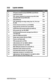
...2-6 2-34 2-11 2-24 2-35 2-28 2-30 2-29 2-31 2-23 2-39 2-25 2-28 2-32 2-35 2-33 2-38 2-36 2-38 2-32 ASUS P5Q-E Series 2-3 2.2.2 Layout contents Connectors/Jumpers/Slots 1. ICH10R Serial ATA connectors [red] (7-pin SATA1-6) 9. Front panel audio connector (10-1 pin AAFP) 20...CPU Socket 3. CPU / Northbridge overvoltage setting (3-pin OV_CPU; 3-pin OV_NB) 6. IEEE 1394a port connector (10-1 pin IE1394_2) 18. Clear RTC RAM (3-pin CLRTC) 12. DDR2 DIMM slots 5. USB connectors (10-1 pin USB78, USB910) 16. Optical drive audio connector (4-pin CD) 19. ...
...2-6 2-34 2-11 2-24 2-35 2-28 2-30 2-29 2-31 2-23 2-39 2-25 2-28 2-32 2-35 2-33 2-38 2-36 2-38 2-32 ASUS P5Q-E Series 2-3 2.2.2 Layout contents Connectors/Jumpers/Slots 1. ICH10R Serial ATA connectors [red] (7-pin SATA1-6) 9. Front panel audio connector (10-1 pin AAFP) 20...CPU Socket 3. CPU / Northbridge overvoltage setting (3-pin OV_CPU; 3-pin OV_NB) 6. IEEE 1394a port connector (10-1 pin IE1394_2) 18. Clear RTC RAM (3-pin CLRTC) 12. DDR2 DIMM slots 5. USB connectors (10-1 pin USB78, USB910) 16. Optical drive audio connector (4-pin CD) 19. ...
User Manual
Page 49
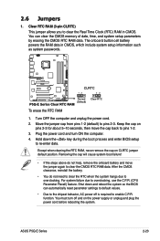
...so the BIOS can clear the CMOS memory of date, time, and system setup parameters by erasing the CMOS RTC RAM data. For system failure due to clear the CMOS RTC RAM data. You can automatically reset parameter settings to default values. • Due to the chipset behavior, AC power ... not help, remove the onboard battery and move the cap back to re-enter data. ASUS P5Q-E Series 2-23 Plug the power cord and turn off is required to overclocking. The onboard button cell battery powers the RAM data in CMOS. Turn OFF the computer and unplug the power cord. 2. 2.6 Jumpers 1....
...so the BIOS can clear the CMOS memory of date, time, and system setup parameters by erasing the CMOS RTC RAM data. For system failure due to clear the CMOS RTC RAM data. You can automatically reset parameter settings to default values. • Due to the chipset behavior, AC power ... not help, remove the onboard battery and move the cap back to re-enter data. ASUS P5Q-E Series 2-23 Plug the power cord and turn off is required to overclocking. The onboard button cell battery powers the RAM data in CMOS. Turn OFF the computer and unplug the power cord. 2. 2.6 Jumpers 1....
User Manual
Page 77
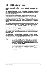
... Defaults item under the Exit Menu. This section explains how to configure your system, or prompted to reconfigure your computer in the CMOS RAM of the SPI chip. If you are for reference purposes only, and may not exactly match what you with its test routines. Do... This motherboard supports a programmable firmware chip that the computer can recognize these changes and record them in the future. The firmware chip on . Press during the Power-On Self-Test (POST) to download the latest BIOS file for this program. Being a menu-driven program, it as possible. ASUS P5Q-E Series...
... Defaults item under the Exit Menu. This section explains how to configure your system, or prompted to reconfigure your computer in the CMOS RAM of the SPI chip. If you are for reference purposes only, and may not exactly match what you with its test routines. Do... This motherboard supports a programmable firmware chip that the computer can recognize these changes and record them in the future. The firmware chip on . Press during the Power-On Self-Test (POST) to download the latest BIOS file for this program. Being a menu-driven program, it as possible. ASUS P5Q-E Series...

User Manual
Page 106
... Select this item shows Installed. After you successfully set your BIOS password, you to change other items appear to allow you to erase the RTC RAM. Confirm the password when prompted. To clear the supervisor password, select the Change Supervisor Password then press . The message "Password Installed" appears after you set... disabled password. The message "Password Uninstalled" appears. 3.7.3 Security The Security menu items allow you can clear it by erasing the CMOS Real Time Clock (RTC) RAM.
... Select this item shows Installed. After you successfully set your BIOS password, you to change other items appear to allow you to erase the RTC RAM. Confirm the password when prompted. To clear the supervisor password, select the Change Supervisor Password then press . The message "Password Installed" appears after you set... disabled password. The message "Password Uninstalled" appears. 3.7.3 Security The Security menu items allow you can clear it by erasing the CMOS Real Time Clock (RTC) RAM.
User Manual
Page 113
... and Exit ESC Exit v02.61 (C)Copyright 1985-2008, American Megatrends, Inc. An onboard backup battery sustains the CMOS RAM so it stays on the Setup menus. Load Setup Defaults This option allows you to load the default values for a... confirmation before saving the values to the non-volatile RAM. Exit & Discard Changes Select this option only if you do not want to save or discard your changes to the... Exit menu items allow you to load the optimal or failsafe default values for this operation. ASUS P5Q-E Series 3-43
... and Exit ESC Exit v02.61 (C)Copyright 1985-2008, American Megatrends, Inc. An onboard backup battery sustains the CMOS RAM so it stays on the Setup menus. Load Setup Defaults This option allows you to load the default values for a... confirmation before saving the values to the non-volatile RAM. Exit & Discard Changes Select this option only if you do not want to save or discard your changes to the... Exit menu items allow you to load the optimal or failsafe default values for this operation. ASUS P5Q-E Series 3-43

User Manual
Page 29
...Page 2-36 2-6 2-33 2-11 2-23 2-34 2-27 2-29 2-28 2-30 2-22 2-38 2-24 2-27 2-31 2-34 2-32 2-37 2-35 2-37 ASUS P5Q-E 2-3 Floppy disk drive connector (34-1 pin FLOPPY) 8. USB connectors (10-1 pin USB78, USB910) 16. Power-on and Reset switch 14. IEEE 1394a port ... Front panel audio connector (10-1 pin AAFP) 20. DDR2 DIMM slots 5. SATA_E2 [white, port 1] 11. Clear RTC RAM (3-pin CLRTC) 12. TPM connector (20-1 pin TPM) 15. ATX power connectors (24-pin EATXPWR, 8-pin ATX12V) 2. ICH10R Serial ATA connectors [red] (7-pin SATA1-6) 9. SIL5723 Serial ATA...
...Page 2-36 2-6 2-33 2-11 2-23 2-34 2-27 2-29 2-28 2-30 2-22 2-38 2-24 2-27 2-31 2-34 2-32 2-37 2-35 2-37 ASUS P5Q-E 2-3 Floppy disk drive connector (34-1 pin FLOPPY) 8. USB connectors (10-1 pin USB78, USB910) 16. Power-on and Reset switch 14. IEEE 1394a port ... Front panel audio connector (10-1 pin AAFP) 20. DDR2 DIMM slots 5. SATA_E2 [white, port 1] 11. Clear RTC RAM (3-pin CLRTC) 12. TPM connector (20-1 pin TPM) 15. ATX power connectors (24-pin EATXPWR, 8-pin ATX12V) 2. ICH10R Serial ATA connectors [red] (7-pin SATA1-6) 9. SIL5723 Serial ATA...

User Manual
Page 48
... down and reboot the system so the BIOS can clear the CMOS memory of date, time, and system setup parameters by erasing the CMOS RTC RAM data. After the CMOS clearance, reinstall the battery. • You do not help, remove the onboard battery and move the cap back to ...overclocking, use the C.P.R. (CPU Parameter Recall) feature. Shut down the key during the boot process and enter BIOS setup to clear the CMOS RTC RAM data. You can automatically reset parameter settings to default values. • Due to the chipset behavior, AC power off and on CLRTC jumper default ...
... down and reboot the system so the BIOS can clear the CMOS memory of date, time, and system setup parameters by erasing the CMOS RTC RAM data. After the CMOS clearance, reinstall the battery. • You do not help, remove the onboard battery and move the cap back to ...overclocking, use the C.P.R. (CPU Parameter Recall) feature. Shut down the key during the boot process and enter BIOS setup to clear the CMOS RTC RAM data. You can automatically reset parameter settings to default values. • Due to the chipset behavior, AC power off and on CLRTC jumper default ...

User Manual
Page 77
...and record them in the CMOS RAM of your computer in the future. otherwise, POST continues with the opportunity to run this section are installing a motherboard, reconfiguring your system using the navigation keys. • The default BIOS settings for this motherboard. If you wish to enter ...prompted to ensure optimum performance. Select the Load Setup Defaults item under the Exit Menu. This requires you with its test routines. ASUS P5Q-E 3-7 Use the BIOS Setup program when you are for most conditions to use as easy to ensure system compatibility and stability. This...
...and record them in the CMOS RAM of your computer in the future. otherwise, POST continues with the opportunity to run this section are installing a motherboard, reconfiguring your system using the navigation keys. • The default BIOS settings for this motherboard. If you wish to enter ...prompted to ensure optimum performance. Select the Load Setup Defaults item under the Exit Menu. This requires you with its test routines. ASUS P5Q-E 3-7 Use the BIOS Setup program when you are for most conditions to use as easy to ensure system compatibility and stability. This...

User Manual
Page 106
...Copyright 1985-2008, American Megatrends, Inc. The message "Password Installed" appears after you can clear it by erasing the CMOS Real Time Clock (RTC) RAM. If you forget your password. The Supervisor Password item on how to change the supervisor password, follow the same steps as in setting a user password...BIOS SETUP UTILITY Boot Security Settings Supervisor Password : Not Installed User Password : Not Installed Change Supervisor Password Change User Password to erase the RTC RAM. To clear the supervisor password, select the Change Supervisor Password then press .
...Copyright 1985-2008, American Megatrends, Inc. The message "Password Installed" appears after you can clear it by erasing the CMOS Real Time Clock (RTC) RAM. If you forget your password. The Supervisor Password item on how to change the supervisor password, follow the same steps as in setting a user password...BIOS SETUP UTILITY Boot Security Settings Supervisor Password : Not Installed User Password : Not Installed Change Supervisor Password Change User Password to erase the RTC RAM. To clear the supervisor password, select the Change Supervisor Password then press .

User Manual
Page 113
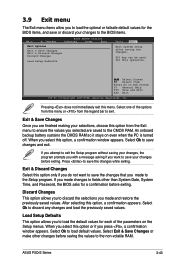
... Discard Changes Load Setup Defaults Tools Exit Exit system setup after saving the changes. An onboard backup battery sustains the CMOS RAM so it stays on the Setup menus. When you select this option or if you select this operation. Select Ok to...default values for this option, a confirmation window appears. Exit & Save Changes Once you selected are saved to save the changes while exiting. ASUS P5Q-E 3-43 Pressing does not immediately exit this option, a confirmation appears. When you press , a confirmation window appears. After selecting this menu....
... Discard Changes Load Setup Defaults Tools Exit Exit system setup after saving the changes. An onboard backup battery sustains the CMOS RAM so it stays on the Setup menus. When you select this option or if you select this operation. Select Ok to...default values for this option, a confirmation window appears. Exit & Save Changes Once you selected are saved to save the changes while exiting. ASUS P5Q-E 3-43 Pressing does not immediately exit this option, a confirmation appears. When you press , a confirmation window appears. After selecting this menu....


